ED
Decision 2021/015/R
1.0 Purpose
This AMC
provides information, guidelines, recommendations, and acceptable means of
compliance for use by applicants in the production of landing performance
information. Operators should use that landing performance information to:
—
support
the dispatch of a flight when planning to land on runways that are slippery
wet or contaminated by standing water, slush, snow, ice, or other
contaminants; and
—
assess the landing performance at the time of arrival in all runway
surface conditions.
2.0 Applicability
of data
Appropriate landing performance data are required for dispatch and for the time-of-arrival landing performance assessments. As the variables to be considered as well as the ways in which that data is to be used vary, the landing performance data for assessing the landing performance at the time of arrival may be different from the landing performance data that are developed in accordance with CS 25.125 and provided in the aeroplane flight manual (AFM) in accordance with CS 25.1587(b).
DRY AND WET RUNWAYS: this AMC 25.1592 includes the methods for deriving the landing distance on dry and wet runways, which is intended to be used for assessing the landing performance at the time of arrival only. For assessing the preflight landing performance when planning to land on a dry or wet runway, the landing distance established in compliance with CS 25.125 should be used.
SLIPPERY WET AND CONTAMINATED RUNWAYS: the data that is derived in accordance with the method(s) included in this AMC is appropriate for assessing the landing performance at the time of arrival and for dispatch, when planning to land on a slippery wet or contaminated runway surface, provided that CS 25.125(c)(3) and CS 25.125(g) are also complied with.
Aeroplane performance data for contaminated runway conditions, which are produced in accordance with CS 25.1592, should include recommendations for their operational use. Where possible, this operational guidance should be provided by the applicant or its production should be co-ordinated with the applicant to ensure that the information is valid for use.
Operators should carefully and conservatively select the appropriate performance data to use in operations on slippery wet and contaminated runways. They should pay special attention to any contaminant being present in the critical high-speed portion of the runway.
When determining the maximum depth of runway contaminants, the applicant should also consider the maximum depth for which the engine air intakes are shown to be free of hazardous ingestion of water in accordance with CS 25.1091(d)(2).
3.0 Standard
assumptions
The data for assessing the landing performance at the time of arrival
should assume the expected landing performance of a trained flight crew of
average skill following normal flight procedures. It should take into account
the following:
—
runway surface conditions/runway condition
codes,
—
winds,
—
temperatures,
—
average runway slopes,
—
pressure altitudes,
—
icing conditions,
—
final-approach speeds,
—
aeroplane weight and configuration, and
—
deceleration devices used.
As the landing distances defined in CS 25.125, the landing distances
to be used for time of arrival landing performance assessments are defined as
the horizontal distance from the point at which the main gear of the aeroplane
is 50 ft above the landing surface to the position where the aeroplane
comes to a stop (see Figure 1 below).
4.0 Definitions
In addition to the terms that are defined in AMC 25.1591, the
applicant should consider the following:
Runway condition code (RWYCC)
RWYCC is a number that is used in the runway condition report and
describes the effect of the runway surface condition(s) on the deceleration
performance and lateral control of the aeroplane (see Section 6.2 of this
AMC for the classification of runway conditions).
Note: the objective of the RWYCC is to enable the flight crew to
calculate the operational performance of the aeroplane. ICAO Doc 9981
‘PROCEDURES FOR AIR NAVIGATION SERVICES (PANS) — Aerodromes’, 3rd Edition,
2020, describes procedures for determining the RWYCC.
5.0 Assumptions
for landing distances
The applicant should provide landing performance data as RWYCCs for
codes six through one within the approved operational envelope for landing.
The applicant may decide to provide additional data for fluid contaminants
(dry snow, wet snow, slush, and standing water) for the range of depths that
are given in Table 2 of Section 7.0 of this AMC.
The applicant does not provide landing performance data for code zero
(0) as this code does not represent a performance category. Code 0 is a
condition in which flight operations should cease on the runway until the
aerodrome improves the braking action.
The applicant should provide the impact of each of the parameters
affecting landing distance, taking into account the following:
—
approved landing configurations, including
Category-III landing guidance, where approved;
—
approved deceleration devices (e.g. wheel
brakes, speed brakes/spoilers, and thrust reversers);
—
pressure altitudes within the approved
operational envelope for landing;
—
weights up to the maximum take-off weight
(MTOW);
—
expected airspeeds at the runway threshold,
including speeds up to the maximum recommended final-approach speed,
considering possible speed additives for winds and icing conditions;
—
temperatures within the approved operational
envelope for landing;
—
operational correction factors for winds
within the established operational limits of the aeroplane for:
—
no more than 50 % of the nominal wind
components along the take-off path opposite to the direction of landing; and
—
no less than 150 % of nominal wind
components along the take-off path in the direction of landing;
—
runway slopes within the approved
operational envelope for landing; and
—
icing conditions if CS 25.125(a)(2)
applies.
6.0 Derivation
of landing distance
The landing distance consists of three segments:
— an airborne segment,
— a transition segment, and
— a final stopping-configuration (full-braking) segment,
as shown in Figure 1.
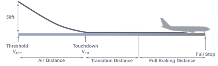
Figure 1 —
Landing-distance segments
The applicant should derive the landing distance
for assessing the landing performance at dispatch, when planning to land on a
dry or wet runway surface, in accordance with CS 25.125.
The applicant should derive the landing distance
for assessing the landing performance at dispatch, when planning to land on a
contaminated or slippery wet runway surface, in accordance with the method(s)
contained in Sections 6 and 7 of this AMC.
The applicant may analytically derive the landing distance for
assessing the landing performance at the time of arrival from the landing
performance model that the applicant developed to show compliance with CS 25.125, modified as
described in the following sections.
The applicant should make changes in the aeroplane’s configuration,
speed, power, and thrust that are used to determine the landing distance for
assessing the landing performance at the time of arrival using procedures that
are established for operation in service. These procedures should:
—
be able to be consistently executed in service by
flight crews of average skill;
—
include safe and reliable methods or devices; and
—
allow for any time delays that may reasonably be
expected in service (see Section 6.2 below).
6.1 Air distance
6.1.1 Default distance allowance
Based on this
section, the applicant should establish a distance allowance for the airborne
phase, which is appropriate to most aeroplanes and types of approaches.
As shown in Figure
1, ‘air distance’ is defined as the distance from an aeroplane height of
15 m (50 ft) above the landing surface to the point of the main-gear
touchdown. This ‘air distance’ definition is the same as the one used for
compliance with CS 25.125. However, an air distance that is
determined under CS 25.125 may not be appropriate for making
operational assessments of the landing performance, as it may be shorter than
the distance that an average pilot is likely to achieve in normal operation.
The air distance
that is used for any landing at any runway is a function of the following
variables:
—
runway
approach guidance;
—
runway
slope;
—
use of
any aeroplane features or equipment (e.g. heads-up guidance, auto-flight
systems, etc.);
—
pilot
technique; and
—
the
inherent flare characteristics of the aeroplane.
Unless the air
distance that is used for compliance with CS 25.125 is representative of an average pilot flying in normal operation (see
flight test demonstration below), the applicant should analytically determine
the air distance that is used for operational assessments of the landing
performance as ‘the distance that is traversed over a period of 7 sec at a
speed of 98 % of the recommended speed above the landing threshold’. The
recommended ‘speed above the landing threshold’ may also be referred to as the
‘final‑approach speed (VAPP)’. The above air distance represents a
flare time of 7 sec and a touchdown speed (VTD) of 96 % of the VAPP.
The VAPP should be consistent with the procedures recommended by
the applicant, including any speed additives, e.g. those that may be used due
to winds or icing conditions. The applicant should also provide the effects of
higher speeds, to account for variations that occur in operations or are
caused by the operating procedures of individual operators.
If the applicant
derives the air distance directly from flight test data instead of using the
analytical method described above, the flight test data should meet the
following criteria:
—
procedures
consistent with the applicant’s recommended procedures for operation in
service should be used; these procedures should address the recommended VAPP,
flare initiation height, thrust/power reduction height and technique, and
target pitch attitudes;
—
at a
height of 15 m (50 ft) above the runway surface, the aeroplane should have an
airspeed not lower than the recommended VAPP; and
—
the
rate of descent at touchdown should be in the range of 0.3-1.2°m/sec (1‑4 ft/sec).
If the air distance
is based on a time of 7 seconds at a speed of 98 % of the recommended speed
above the runway threshold, this air distance is considered valid for downhill
runway slopes of up to 2 % in magnitude (no credit should be taken for uphill
runway slopes).
6.1.2 Steep-approach landing
The distance
allowance described in Section 6.1.1 may not be appropriate for steep
approaches. Therefore, this paragraph provides information for determining the
air distance at a steep approach using a glide path greater than or equal to
4.5 °.
The applicant
determines air distances that are achieved at steep approaches directly from
flight tests performed in accordance with CS-25
Appendix Q. The applicant
may use those demonstrated air distances for assessing the landing distance at
dispatch and at the time of arrival, in lieu of complying with the air
distances provided for in Section 6.1.1.
6.2 Transition distance
As shown in Figure
1, ‘transition distance’ is defined as ‘the distance from the point of the
main-gear touchdown to the point where all deceleration devices that are used
for determining the landing distance are operating. If the air distance is
based on a time of 7 sec at a speed of 98 % of the recommended speed
above the runway threshold, the speed at the start of the transition segment
should be 96 % of the recommended speed above the runway threshold.
The applicant should
determine the transition distance based on the recommended procedures for use
of the approved means of deceleration, both in terms of sequencing and of cues
for initiation. The applicant should also consider reasonably expected time delays.
For procedures that
call for the initiation of deceleration devices at nose gear touchdown, the
minimum time for each pilot action to deploy or activate a deceleration means
should be the demonstrated time but no less than 1 second.
For procedures that
call for the initiation of deceleration devices prior to nose gear touchdown,
the minimum time for each pilot action to deploy or activate a deceleration
means should be the demonstrated time plus 1 second.
For automatically
deployed or activated deceleration means (e.g. auto-speedbrakes or auto‑brakes),
the demonstrated time may be used with no added delay.
When determining the
distance of the transition segment, as well the speed at the start of the
final stopping-configuration segment, the applicant should consider the
expected evolution of the braking force that is achieved over the transition
distance. The evolution of the braking force should include any differences
that may occur for different RWYCCs, e.g. regarding the aeroplane transition
to the full-braking configuration (see Table 1 for the wheel-braking
coefficient of the full-braking configuration for each runway surface
condition and reported RWYCC).
|
RWYCC |
Runway surface condition description |
Wheel-braking coefficient |
|
6 |
DRY |
90 % of the certified value that is used to
comply with CS 25.1251 |
|
5 |
FROST WET (the runway surface is
covered by any visible dampness or water up to, and including, 3 mm deep SLUSH (up to, and including,
3 mm deep) DRY SNOW (up to, and including,
3 mm deep) WET SNOW (up to, and including,
3 mm deep) |
As per the method that is defined in CS 25.109(c) |
|
4 |
COMPACTED SNOW (outside air
temperature of less than or equal to -15 °C/5 °F) |
0.202 |
|
3 |
WET (‘Slippery wet’
runway) DRY SNOW (more than 3 mm deep) WET SNOW (more than 3 mm deep) DRY SNOW ON TOP OF COMPACTED SNOW (of
any depth) WET SNOW ON TOP OF COMPACTED SNOW (of
any depth) COMPACTED SNOW (outside air
temperature of more than -15° C/5 °F) |
0.162 |
|
2 |
STANDING WATER (more than 3 mm
deep) SLUSH (more than 3 mm deep) |
(a) For speeds below 85 % of the aquaplaning
speed3, 50 % of the wheel‑braking coefficient that is determined
in accordance with CS 25.109(c),
but no greater than 0.162 (b) For speeds equal to or higher than 85 %
of the aquaplaning speed3, 0.052 |
|
1 |
ICE |
0.072 |
|
0 |
WET ICE WATER ON TOP OF COMPACTED SNOW DRY SNOW OR WET SNOW ON TOP OF ICE |
Not applicable (no operations in ‘RWYCC = 0’
conditions) |
Table 1 —
Correlation between wheel-braking coefficient and RWYCC
1 The applicant may use 100 % of the wheel-braking coefficient that is used to comply with CS 25.125 if the testing from which that braking coefficient was derived was conducted on portions of runways with operationally representative amounts of rubber contamination and paint stripes.
2 For these wheel-braking coefficients, the applicant should assume a fully modulating anti‑skid system. For quasi-modulating systems, the applicant should multiply the listed wheel-braking coefficient by 0.625. For on-off systems, the applicant should multiply the listed wheel-braking coefficient by 0.375. For the classification of anti-skid systems, refer to AMC 25.109(c)(2). The applicant should address aeroplanes without anti-skid systems separately, on a case-by-case basis.
3 The aquaplaning speed ‘VP’ may be estimated by solving the equation ‘VP = 9√𝑃’, where ‘VP’ is the ground speed in kt and ‘P’ is the tyre pressure in lb/in2. To estimate the effect of aquaplaning on wheel-to-ground friction, the aquaplaning speed (VP) given above should be factored by a coefficient of 0.85.
6.3 Final stopping-configuration distance (Full-braking distance)
As shown in Figure 1, the final stopping-configuration (full-braking) segment begins at the end of the transition segment, where all deceleration devices that are used for determining the landing distance are operating. The full-braking segment ends at the nose gear position where the aeroplane comes to a stop.
The applicant should calculate the final stopping-configuration distance based on the wheel braking coefficient that is appropriate for the runway surface condition or RWYCC, including the effect of aquaplaning, if applicable. The applicant may use a means other than wheel brakes to determine the landing distances if that means complies with CS 25.109(e) and CS 25.109(f), except for time-of-arrival dry runway landing distances, where the applicant may consider the effects of the available reverse thrust. The applicant may take credit for using a thrust reverser if the design of that reverser fulfils the criteria of AMC 25.109(f), except for the demonstration requirements of Section 6 of this AMC. Using a thrust reverser may reduce directional controllability in combinations of crosswinds and low friction conditions. The applicant should provide to operators recommendations or guidelines for crosswind landings, including the maximum recommended crosswinds, for the RWYCCs for which landing-distance data is provided. The applicant may carry out a suitable simulation to develop these guidelines for operation on contaminated runways (see Section 7 on considering contaminant drag from loose contaminants).
6.4 Landing-distance
data for dispatch
For dispatch computation, performance data for landing on a contaminated runway surface may include credit for reverse thrust in compliance with CS 25.125(c)(3) and CS 25.125(g); CS 25.125(g) requires to consider the one engine inoperative configuration. The applicant should assume that the engine fails during the landing flare. If this adversely affects the availability of a deceleration device, then the applicant, in compliance with CS 25.125(g), must compare:
(a) the normal landing distance without engine failure, using the available deceleration means factored by 1.15; and
(b) the unfactored landing distance, assuming an engine failure in the landing flare and loss of availability of any related deceleration means.
The scheduled landing distance is the longer between (a) and (b) above. Such distance is the minimum landing distance that already includes an operational factor of 1.15.
6.5 Time-of-arrival landing distance
For time-of-arrival landing distances, CS 25.125(g) does not need to be applied.
7.0 Contaminant
drag — standing water, slush, wet snow
Loose contaminants result in additional contaminant drag due to the combination of the following:
— the aeroplane tyres displace the contaminant; and
— the contaminant spray is impinged upon the airframe.
Such contaminant drag is an additional force that helps decelerate the aeroplane, thus reducing the distance needed to stop the aeroplane. As the contaminant drag increases with the contaminant depth, the deeper the contaminant is, the shorter the stopping distance will be. However, the actual contaminant depth may be less than the reported depth for the following reasons:
— contaminant depths are reported in runway surface condition reports using specific depth increments;
—
the procedure for reporting contaminant
depths is to report the highest depth of the contaminant along the reported
portion of the runway surface; contaminant depths, however, may not be uniform
over the whole runway surface (or reported portion of the runway surface),
therefore, areas of lower contaminant depth are likely;
— in a stable weather environment (the contaminant is not replenished on the runway), the contaminant depth is likely to decrease as successive aeroplanes use the runway displacing the contaminant; and
— contaminated conditions are reported starting from 25 % coverage in each runway third; the total coverage of the runway with significant depths of contaminant may thus be less than 10 % of the entire runway surface.
If the actual contaminant depth is lower than the reported value, using
the reported value to determine the contaminant drag will result in a higher
drag level than the actual one, leading to an optimistic prediction of the
stopping distance. Therefore, it is recommended not to include the effect of
contaminant drag when calculating the landing distances for assessing the
landing performance at the time of arrival. However, if the effect of
contaminant drag is included, the applicant should limit it to no more than
the drag resulting from 50 % of the reported depth.
If the effect of contaminant depth is included in the landing-distance
data, the applicant should provide data for up to the maximum depth of each
runway contaminant, for which landing operations are permitted. When
determining the maximum depth of runway contaminants, the applicant may need
to consider the maximum depth for which the engine air intakes are shown to be
free of hazardous ingestion of water in accordance with CS 25.1091(d)(2).
If the effect of contaminant depth is included in the landing distance
data, then the applicant should provide data for the specific gravities as
shown in Table 2:
|
Loose contaminant |
Specific gravity |
|
Standing
water |
1.0 |
|
Slush |
0.85 |
|
Dry snow |
0.2 |
|
Wet snow |
0.5 |
Table 2 — Specific gravity of loose
contaminants
For the method of determining the contaminant drag,
refer to AMC 25.1591.
8.0 Presentation
of supplementary performance information
8.1 General
The applicant should include in the performance information for dry, wet, slippery wet, and contaminated runways, derived in accordance with Sections 5.0-7.0 of this AMC, the following statements or equivalent ones:
— operation on runways that are contaminated with water, slush, snow, ice, or other contaminants implies uncertainties regarding runway friction and contaminant drag; therefore, the achievable performance and control of the aeroplane during landing are also uncertain as the actual conditions may not completely match the assumptions on which the performance information was based; where possible, every effort should be made to ensure that the runway surface is cleared of significant contamination;
— the performance information has been established with the assumption that any runway contaminant is of uniform depth and density; and
— ground handling characteristics on contaminated runways should not be considered equivalent to those that may be achieved on dry or wet runways, in particular following an engine failure, in presence of crosswinds, or when using reverse thrust.
8.2 Procedures
In addition to performance information for operating on contaminated runways, the applicant should include in the AFM recommended procedures associated with this performance information if such procedures are specific to the aeroplane. The applicant should also include in the AFM changes in other procedures, e.g. reference to crosswinds, to adapt them to the operation of the aeroplane on a contaminated runway.
8.3 Landing data
The applicant should present landing data:
— either as separate data appropriate to a defined runway contaminant; or
— as incremental data based on the dry or wet runway information in the AFM.
The applicant should also include information on the use of speeds higher than the reference landing speed (VREF) on landing, i.e. speeds up to the maximum recommended approach speed in addition to the VREF, as well as on the related distances. The applicant should present the landing distance either directly or along with the factors that are required by the applicable air operations regulations, including a clear explanation, where appropriate.
Where the applicant provides data for a range of contaminant depths, e.g. greater than 3, 6, 9, 12, or 15 mm, then the AFM should clearly indicate how to define data for contaminant depths within the range of the contaminant depths provided.
When for at least one runway condition, the landing distances to be used at the time of dispatch are defined by the unfactored distance that is determined with one engine assumed to be failing in the flare, the applicant should present all landing distances at the time of dispatch as factored distances in the AFM. The AFM should clearly state this to avoid double application of operational factors.
The AFM should provide:
(a) definitions of runway surface conditions;
(b) the performance data for operations on contaminated runways;
(c) landing distances on contaminated runways;
(d) data with no reverse thrust credit to:
(1) cover operational restrictions on the use of reversers; and
(2) make flight crew aware of the importance of reverser selection on contaminated runways;
(e) the procedures and assumptions that are used to develop the performance data; and
(f) the appropriate statements as per Section 8.1 of this AMC.
The applicant should provide instructions on the use of the data in the appropriate operational documentation.
9.0 References
Federal Aviation Administration (FAA) Advisory Circular (AC) 25-32, ‘Landing Performance Data for Time-of-Arrival Landing Performance Assessments’, 22 December 2015.
[Amdt No: 25/27]