AMC
25.109(c)(2) Accelerate-stop distance: anti-skid system efficiency
ED Decision 2003/2/RM
CS 25.109(c)(2) identifies 3 categories of anti-skid system and provides for either the use of a default efficiency value appropriate to the type of system or the determination of a specific efficiency value. Paragraph 1 of this AMC gives a description of the operating characteristics of each category to enable the classification of a particular system to be determined. Paragraph 2 gives an acceptable means of compliance with the requirement for flight testing and use of default efficiency values in accordance with CS 25.109(c)(2). These values are appropriate where the tuning of the anti-skid system is largely qualitative and without detailed quantitative analysis of system performance. Where detailed data recording and analysis is used to optimise system tuning, an efficiency value somewhat higher than the default value might be obtained and determined. Typically, a value of 40% might be achieved with an On/Off system. The quasi-modulating category covers a broad range of systems with varying performance levels. The best quasi-modulating systems might achieve an efficiency up to approximately 80%. Fully modulating systems have been tuned to efficiencies greater than 80% and up to a maximum of approximately 92%, which is considered to be the maximum efficiency on a wet runway normally achievable with fully modulating digital anti-skid systems. Paragraph 3 gives an acceptable means of compliance with CS 25.109(c)(2) where the applicant elects to determine a specific efficiency value.
In Paragraph 4 of this AMC, guidance is given on the use of 2 alternative methods for calculating antiskid system efficiency from the recorded data. One method is based on the variation of brake torque throughout the stop, while the other is based on wheel speed slip ratio. Finally, Paragraph 5 gives guidance on accounting for the distribution of the normal load between braked and unbraked wheels.
1 Classification of anti-skid system types
1.1 For the purposes of determining the default anti-skid efficiency value under CS 25.109(c)(2), anti-skid systems have been grouped into three broad classifications; on/off, quasi-modulating and fully modulating. These classifications represent evolving levels of technology and performance capabilities on both dry and wet runways.
1.2 On/off systems are the simplest of the three types of anti-skid systems. For these systems, fully metered brake pressure (as commanded by the pilot) is applied until wheel locking is sensed. Brake pressure is then released to allow the wheel to spin back up. When the system senses that the wheel is accelerating back to synchronous speed (i.e. ground speed), full metered pressure is again applied. The cycle of full pressure application/complete pressure release is repeated throughout the stop (or until the wheel ceases to skid with brake pressure applied).
1.3 Quasi-modulating systems attempt to continuously regulate brake pressure as a function of wheel speed. Typically, brake pressure is released when the wheel deceleration rate exceeds a preselected value. Brake pressure is re-applied at a lower level after a length of time appropriate to the depth of skid. Brake pressure is then gradually increased until another incipient skid condition is sensed. In general, the corrective actions taken by these systems to exit the skid condition are based on a pre-programmed sequence rather than the wheel speed time history.
1.4 Fully modulating systems are a further refinement of the quasi-modulating systems. The major difference between these two types of anti-skid systems is in the implementation of the skid control logic. During a skid, corrective action is based on the sensed wheel speed signal, rather than a preprogrammed response. Specifically, the amount of pressure reduction or reapplication is based on the rate at which the wheel is going into or recovering from a skid. Also, higher fidelity transducers and upgraded control systems are used, which respond more quickly.
1.5 In addition to examining the control system differences noted above, a time history of the response characteristics of the anti-skid system during a wet runway stop should be used to help identify the type of anti-skid system. Comparing the response characteristics from wet and dry runway stops can also be helpful.
Figure 1 shows an example of the response characteristics of a typical on-off system on both wet and dry runways. In general, the on-off system exhibits a cyclic behaviour of brake pressure application until a skid is sensed, followed by the complete release of brake pressure to allow the wheel to spin back up. Full metered pressure (as commanded by the pilot) is then re-applied, starting the cycle over again. The wheel speed trace exhibits deep and frequent skids (the troughs in the wheel speed trace), and the average wheel speed is significantly less than the synchronous speed (which is represented by the flat topped portions of the wheel speed trace). Note that the skids are deeper and more frequent on a wet runway than on a dry runway. For the particular example shown in Figure 1, the brake becomes torque-limited toward the end of the dry runway stop and is unable to generate enough torque to cause further skidding.
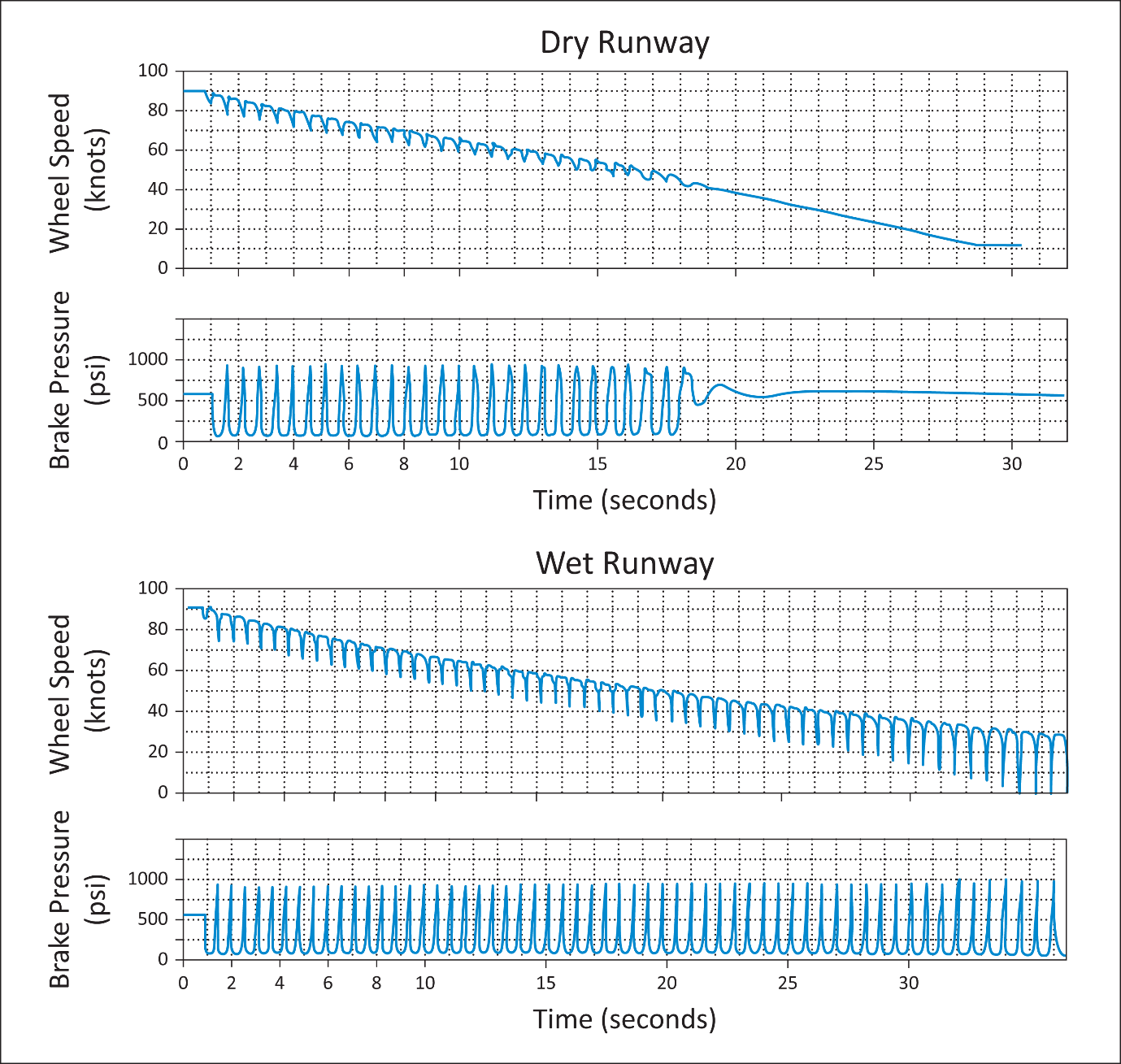
FIGURE 1.
ANTI-SKID SYSTEM RESPONSE CHARACTERISTICS On-Off System
The effectiveness of quasi-modulating systems can vary significantly depending on the slipperiness of the runway and the design of the particular control system. On dry runways, these systems typically perform very well; however, on wet runways their performance is highly dependent on the design and tuning of the particular system. An example of the response characteristics of one such system is shown in Figure 2. On both dry and wet runways, brake pressure is released to the extent necessary to control skidding. As the wheel returns to the synchronous speed, brake pressure is quickly increased to a pre-determined level and then gradually ramped up to the full metered brake pressure. On a dry runway, this type of response reduces the depth and frequency of skidding compared to an on-off system. However, on a wet runway, skidding occurs at a pressure below that at which the gradual ramping of brake pressure occurs. As a result, on wet runways the particular system shown in Figure 2 operates very similarly to an on-off system.
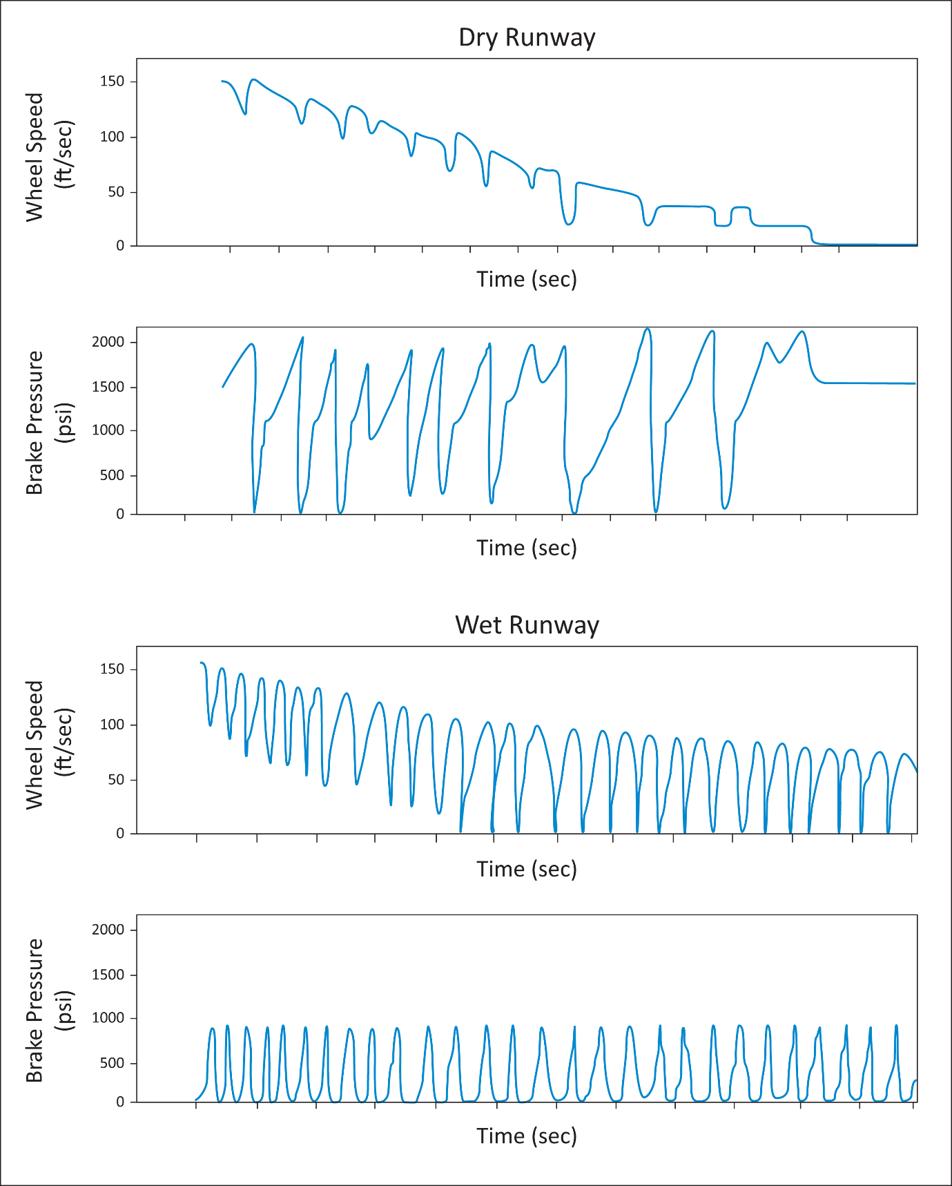
FIGURE 2.
ANTI-SKID SYSTEM RESPONSE CHARACTERISTICS Quasi-Modulating System
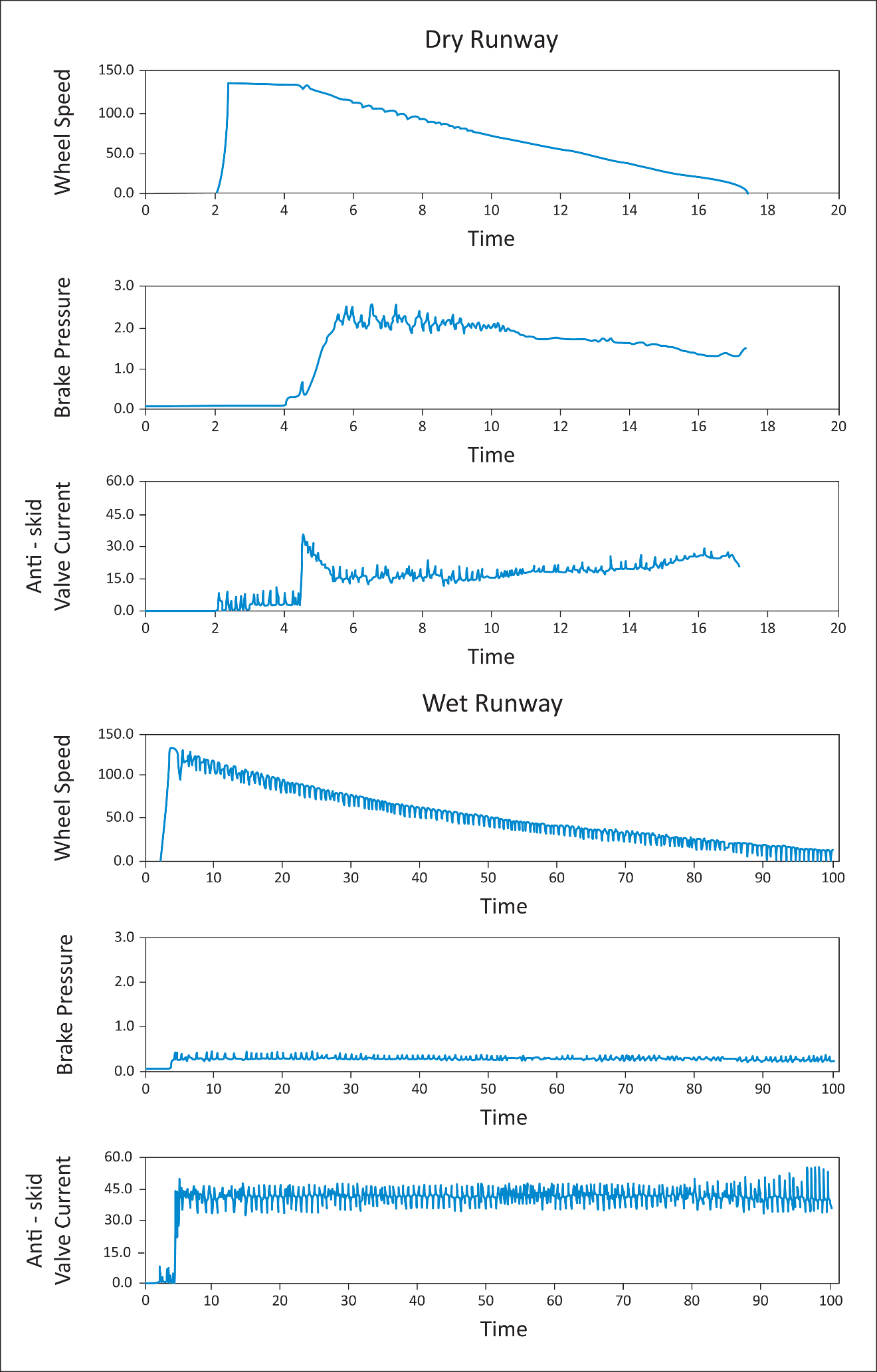
FIGURE 3.
ANTI-SKID SYSTEM RESPONSE CHARACTERISTICS Fully Modulating System
When properly tuned, fully modulating systems are characterised by much smaller variations in brake pressure around a fairly high average value. These systems can respond quickly to developing skids and are capable of modulating brake pressure to reduce the frequency and depth of skidding. As a result, the average wheel speed remains much closer to the synchronous wheel speed. Figure 3 illustrates an example of the response characteristics of a fully modulating system on dry and wet runways.
2 Demonstration of anti-skid system operation when using the
anti-skid efficiency values specified in CS 25.109(c)(2)
2.1 If the applicant elects to use one of the anti-skid efficiency values specified in CS 25.109(c)(2), a limited amount of flight testing must still be conducted to verify that the anti-skid system operates in a manner consistent with the type of anti-skid system declared by the applicant. This testing should also demonstrate that the anti-skid system has been properly tuned for operation on wet runways.
2.2 A minimum of one complete stop, or equivalent segmented stops, should be conducted on a smooth (i.e. not grooved or porous friction course) wet runway at an appropriate speed and energy to cover the critical operating mode of the anti-skid system. Since the objective of the test is to observe the operation (i.e. cycling) of the anti-skid system, this test will normally be conducted at an energy well below the maximum brake energy condition.
2.3 The section of the runway used for braking should be well soaked (i.e. not just damp), but not flooded. The runway test section should be wet enough to result in a number of cycles of anti-skid activity, but should not cause hydroplaning.
2.4 Before taxy and with cold tyres, the tyre pressure should be set to the highest value appropriate to the take-off weight for which approval is being sought.
2.5 The tyres and brakes should not be new, but need not be in the fully worn condition. They should be in a condition considered representative of typical in-service operations.
2.6 Sufficient data should be obtained to determine whether the system operates in a manner consistent with the type of anti-skid system declared by the applicant, provide evidence that full brake pressure is being applied upstream of the anti-skid valve during the flight test demonstration, determine whether the anti-skid valve is performing as intended and show that the anti-skid system has been properly tuned for a wet runway.
Typically, the following parameters should be plotted versus time:
(i) The speed of a representative number of wheels.
(ii) The hydraulic pressure at each brake (i.e. the hydraulic pressure downstream of the anti-skid valve, or the electrical input to each anti-skid valve).
(iii) The hydraulic pressure at each brake metering valve (i.e. upstream of the anti-skid valve).
2.7 A qualitative assessment of the anti-skid system response and aeroplane controllability should be made by the test pilot(s). In particular, pilot observations should confirm that:
(i) Anti-skid releases are neither excessively deep nor prolonged;
(ii) The gear is free of unusual dynamics; and
(iii) The aeroplane tracks essentially straight, even though runway seams, water puddles and wetter patches may not be uniformly distributed in location or extent.
3 Determination of a specific wet runway anti-skid system
efficiency
3.1 If the applicant elects to derive the anti-skid system efficiency from flight test demonstrations, sufficient flight testing, with adequate instrumentation, must be conducted to ensure confidence in the value obtained. An anti-skid efficiency of 92% (i.e. a factor of 0·92) is considered to be the maximum efficiency on a wet runway normally achievable with fully modulating digital anti-skid systems.
3.2 A minimum of three complete stops, or equivalent segmented stops, should be conducted on a wet runway at appropriate speeds and energies to cover the critical operating modes of the anti-skid system. Since the objective of the test is to determine the efficiency of the anti-skid system, these tests will normally be conducted at energies well below the maximum brake energy condition. A sufficient range of speeds should be covered to investigate any variation of the anti-skid efficiency with speed.
3.3 The testing should be conducted on a smooth (i.e. not grooved or porous friction course) runway.
3.4 The section of the runway used for braking should be well soaked (i.e. not just damp), but not flooded. The runway test section should be wet enough to result in a number of cycles of anti-skid activity, but should not cause hydroplaning.
3.5 Before taxy and with cold tyres, the tyre pressure should be set to the highest value appropriate to the take-off weight for which approval is being sought.
3.6 The tyres and brake should not be new, but need not be in the fully worn condition. They should be in a condition considered representative of typical in-service operations.
3.7 A qualitative assessment of anti-skid system response and aeroplane controllability should be made by the test pilot(s). In particular, pilot observations should confirm that:
(i) The landing gear is free of unusual dynamics; and
(ii) The aeroplane tracks essentially straight, even though runway seams, water puddles and wetter patches may not be uniformly distributed in location or extent.
3.8 The wet runway anti-skid efficiency value should be determined as described in Paragraph 4 of this AMC. The test instrumentation and data collection should be consistent with the method used.
4 Calculation of anti-skid system efficiency
4.1 Paragraph 3 above provides guidance on the flight testing required to support the determination of a specific anti-skid system efficiency value. The following paragraphs describe 2 methods of calculating an efficiency value from the data recorded. These two methods, which yield equivalent results, are referred to as the torque method and the wheel slip method. Other methods may also be acceptable if they can be shown to give equivalent results.
4.2 Torque Method
Under the torque method, the anti-skid system efficiency is determined by comparing the energy absorbed by the brake during an actual wet runway stop to the energy that is determined by integrating, over the stopping distance, a curve defined by connecting the peaks of the instantaneous brake force curve (see figure 4). The energy absorbed by the brake during the actual wet runway stop is determined by integrating the curve of instantaneous brake force over the stopping distance.
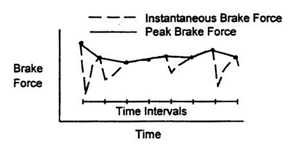
FIGURE
4. INSTANTANEOUS BRAKE FORCE AND PEAK BRAKE FORCE
Using data obtained from the wet runway stopping tests of paragraph 3, instantaneous brake force can be calculated from the following relationship:
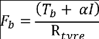
where:
Fb = brake force
Tb = brake torque
α = wheel acceleration
I = wheel moment of inertia; and
Rtyre = tyre radius
For brake installations where measuring brake torque directly is impractical, torque may be determined from other parameters (e.g. brake pressure) if a suitable correlation is available. Wheel acceleration is obtained from the first derivative of wheel speed. Instrumentation recording rates and data analysis techniques for wheel speed and torque data should be well matched to the anti-skid response characteristics to avoid introducing noise and other artifacts of the instrumentation system into the data.
Since the derivative of wheel speed is used in calculating brake force, smoothing of the wheel speed data is usually necessary to give good results. The smoothing algorithm should be carefully designed as it can affect the resulting efficiency calculation. Filtering or smoothing of the brake torque or brake force data should not normally be done. If conditioning is applied, it should be done in a conservative manner (i.e. result in a lower efficiency value) and should not misrepresent actual aeroplane/system dynamics.
Both the instantaneous brake force and the peak brake force should be integrated over the stopping distance. The anti-skid efficiency value for determining the wet runway accelerate-stop distance is the ratio of the instantaneous brake force integral to the peak brake force integral:
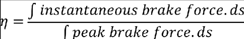
where:
η = anti-skid efficiency; and
s = stopping distance
The stopping distance is defined as the distance travelled during the specific wet runway stopping demonstration, beginning when the full braking configuration is obtained and ending at the lowest speed at which anti-skid cycling occurs (i.e. the brakes are not torque limited), except that this speed need not be less than 19 km/h (10 kt). Any variation in the anti-skid efficiency with speed should also be investigated, which can be accomplished by determining the efficiency over segments of the total stopping distance. If significant variations are noted, this variation should be reflected in the braking force used to determine the accelerate-stop distances (either by using a variable efficiency or by using a conservative single value).
4.3 Wheel Slip Method
At brake application, the tyre begins to slip with respect to the runway surface, i.e. the wheel speed slows down with respect to the aeroplane’s ground speed. As the amount of tyre slip increases, the brake force also increases until an optimal slip is reached. If the amount of slip continues to increase past the optimal slip, the braking force will decrease.
Using the wheel slip method, the anti-skid efficiency is determined by comparing the actual wheel slip measured during a wet runway stop to the optimal slip. Since the wheel slip varies significantly during the stop, sufficient wheel and ground speed data must be obtained to determine the variation of both the actual wheel slip and the optimal wheel slip over the length of the stop. A sampling rate of at least 16 samples per second for both wheel speed and ground speed has been found to yield acceptable fidelity.
For each wheel and ground speed data point, the instantaneous anti-skid efficiency value should be determined from the relationship shown in Figure 5:
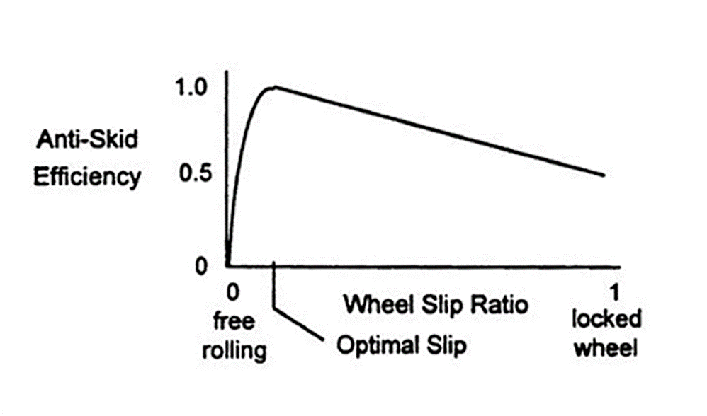
FIGURE
5. ANTI-SKID EFFICIENCY – WHEEL SLIP RELATIONSHIP
WSR = wheel slip ratio = 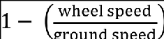
OPS = optimal
slip ratio; and
ηi = instantaneous anti-skid efficiency
To determine the overall anti-skid efficiency value
for use in calculating the wet runway accelerate-stop distance, the
instantaneous anti-skid efficiencies should be integrated with respect to
distance and divided by the total stopping distance:
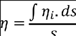
where:
η = anti-skid efficiency; and
s = stopping distance
The stopping distance is defined as the distance travelled during the specific wet runway stopping demonstration, beginning when the full braking configuration is obtained and ending at the lowest speed at which anti-skid cycling occurs (i.e. the brakes are not torque limited), except that this speed need not be less than 19 km/h (10 kt). Any variation in the anti-skid efficiency with speed should also be investigated, which can be accomplished by determining the efficiency over segments of the total stopping distance. If significant variations are noted, this variation should be reflected in the braking force used to determine the accelerate-stop distances (either by using a variable efficiency or by using a conservative single value).
The applicant should provide substantiation of the optimal wheel slip value(s) used to determine the anti-skid efficiency value. An acceptable method for determining the optimal slip value(s) is to compare time history plots of the brake force and wheel slip data obtained during the wet runway stopping tests. For brake installations where measuring brake force directly is impractical, brake force may be determined from other parameters (e.g. brake pressure) if a suitable correlation is available. For those skids where wheel slip continues to increase after a reduction in the brake force, the optimal slip is the value corresponding to the brake force peak. See Figure 6 for an example and note how both the actual wheel slip and the optimal wheel slip can vary during the stop.
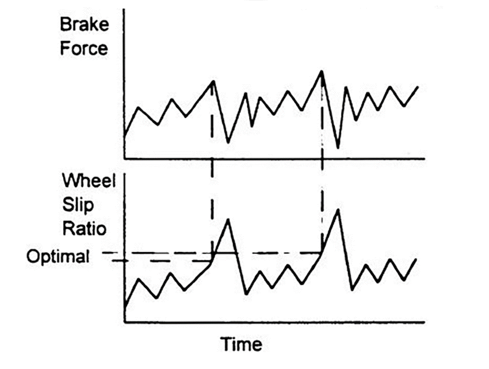
FIGURE
6. SUBSTANTIATION OF THE OPTIMAL SLIP VALUE
4.4 For dispatch with an inoperative anti-skid system (if approved), the wet runway acceleratestop distances should be based on an efficiency no higher than that allowed by CS 25.109(c)(2) for an on-off type of anti-skid system. The safety of this type of operation should be demonstrated by flight tests conducted in accordance with Paragraph 2 of this AMC.
5 Distribution of normal load between braked and unbraked wheels
In addition to taking into account the efficiency of the anti-skid system, CS 25.109(b)(2)(ii) also requires adjusting the braking force for the effect of the distribution of the normal load between braked and unbraked wheels at the most adverse centre of gravity position approved for take-off. The stopping force due to braking is equal to the braking coefficient multiplied by the normal load (i.e. weight) on each braked wheel. The portion of the aeroplane’s weight being supported by the unbraked wheels (e.g. unbraked nose wheels) does not contribute to the stopping force generated by the brakes. This effect must be taken into account for the most adverse centre of gravity position approved for take-off, considering any centre of gravity shifts that occur due to the dynamics of the stop. The most adverse centre of gravity position is the position that results in the least load on the braked wheels.