AMC 25.933(a)(1) Unwanted in-flight thrust reversal of turbojet
thrust reversers
ED
Decision 2020/001/R
1. PURPOSE.
This
Acceptable Means of Compliance (AMC) describes various acceptable means, for
showing compliance with the requirements of CS 25.933(a)(1), "Reversing
systems", of CS-25. These means are intended to provide guidance to supplement
the engineering and operational judgement that must form the basis of any
compliance findings relative to in-flight thrust reversal of turbojet thrust
reversers.
2. RELATED
CERTIFICATION SPECIFICATIONS.
CS 25.111, CS 25.143, CS 25.251, CS 25.571, CS 25.901, CS 25.903, CS 25.1155,
CS 25.1305,
CS 25.1309, CS 25.1322 and CS 25.1529
3. APPLICABILITY.
The
requirements of CS 25.933 apply to turbojet thrust reverser systems. CS 25.933(a) specifically applies to reversers intended for ground operation
only, while CS 25.933(b) applies to reversers intended for both ground
and in-flight use.
This AMC
applies only to unwanted thrust reversal in flight phases when the landing
gear is not in contact with the ground; other phases (i.e., ground operation)
are addressed by CS 25.901(c) and CS 25.1309.
4. BACKGROUND.
4.a. General. Most thrust reversers are intended
for ground operation only. Consequently, thrust reverser systems are generally
sized and developed to provide high deceleration forces while avoiding foreign
object debris (FOD) ingestion, aeroplane surface efflux impingement, and
aeroplane handling difficulty during landing roll. Likewise, aircraft flight
systems are generally sized and developed to provide lateral and directional
controllability margins adequate for handling qualities, manoeuvrability
requirements, and engine-out VMC lateral drift conditions.
In early
turbojet aeroplane designs, the combination of control system design and
thrust reverser characteristics resulted in control margins that were capable
of recovering from unwanted in-flight thrust reversal even on ground-use-only
reversers; this was required by the previous versions of CS 25.933.
As the
predominant large aeroplane configuration has developed into the high bypass
ratio twin engine-powered model, control margins for the in-flight thrust
reversal case have decreased. Clearly,
whenever and wherever thrust reversal is intended, the focus must remain on
limiting any adverse effects of thrust reversal. However, when demonstrating compliance with CS
25.933(a) or CS 25.933(b), the Authority has accepted that applicants may
either provide assurance that the aeroplane is controllable after an in-flight
thrust reversal event or that the unwanted in-flight thrust reversal event
will not occur.
Different
historical forms of the rule have attempted to limit either the effect or the
likelihood of unwanted thrust reversal during flight. However, experience has demonstrated that
neither method is always both practical and effective. The current rule, and this related advisory
material, are intended to allow either of these assurance methods to be
applied in a manner which recognises the limitations of each, thereby maximising
both the design flexibility and safety provided by compliance with the rule.
4.b. Minimising Adverse Effects. The primary
purpose of reversing systems, especially those intended for ground operation
only, is to assist in decelerating the aeroplane during landing and during an
aborted take-off. As such, the reverser must be rapid-acting and must be
effective in producing sufficient reverse thrust. These requirements result in
design characteristics (actuator sizing, efflux characteristics, reverse
thrust levels, etc.) that, in the event of thrust during flight, could cause
significant adverse effects on aeroplane controllability and performance.
If the
effect of the thrust reversal occurring in flight produces an unacceptable
risk to continued safe flight and landing, then the reverser operation and
de-activation system must be designed to prevent unwanted thrust reversal. Alternatively, for certain aeroplane
configurations, it may be possible to limit the adverse impacts of unwanted
thrust reversal on aeroplane controllability and performance such that the
risk to continued safe flight and landing is acceptable (discussed later in
this AMC).
For
reversing systems intended for operation in flight, the reverser system must
be designed to adequately protect against unwanted in-flight thrust reversal.
CS 25.1309
and CS 25.901(c) and the associated AMC (AMC 25.1309
and AMC 25.901(c) provide guidance for developing and assessing
the safety of systems at the design stage. This methodology should be applied
to the total reverser system, which includes:
—
the
reverser;
—
the
engine (if it can contribute to thrust reversal);
—
the
reverser motive power source;
—
the
reverser control system;
—
the
reverser command system in the cockpit; and
—
the
wiring, cable, or linkage system between the cockpit and engine.
Approved
removal, deactivation, reinstallation, and repair procedures for any element
in the reverser or related systems should result in a safety level equivalent
to the certified baseline system configuration.
Qualitative
assessments should be done, taking into account potential human errors
(maintenance, aeroplane operation).
Data
required to determine the level of the hazard to the aeroplane in case of
in-flight thrust reversal and, conversely, data necessary to define changes to
the reverser or the aeroplane to eliminate the hazard, can be obtained from
service experience, test, and/or analysis.
These data also can be used to define the envelope for continued safe
flight.
There are
many opportunities during the design of an aeroplane to minimise both the
likelihood and severity of unwanted in-flight thrust reversal. These opportunities include design features
of both the aeroplane and the engine/reverser system. During the design process, consideration
should be given to the existing stability and control design features, while
preserving the intended function of the thrust reverser system.
Some design
considerations, which may help reduce the risk from in-flight thrust reversal,
include:
4.b.(1)
Engine location to:
(i) Reduce sensitivity to efflux impingement.
(ii) Reduce effective reverse thrust moment
arms
4.b.(2)
Engine/Reverser System design to:
(i) Optimise engine/reverser system integrity
and reliability.
(ii) Rapidly reduce engine airflow (i.e.
auto-idle) in the event of an unwanted thrust reversal. Generally, such a feature is considered a
beneficial safety item. In this case, the probability and effect of any
unwanted idle command or failure to provide adequate reverse thrust when
selected should be verified to be consistent with AMC 25.1309 and AMC 25.901(c).
(iii) Give consideration to the aeroplane pitch,
yaw, and roll characteristics.
(iv) Consider effective efflux diameter.
(v) Consider efflux area.
(vi) Direct reverser efflux away from critical
areas of the aeroplane.
(vii) Expedite detection of unwanted thrust
reversal, and provide for rapid compensating action within the reversing
system.
(viii) Optimise positive aerodynamic stowing
forces.
(ix) Inhibit in-flight thrust reversal of
ground-use-only reversers, even if commanded by the flight crew.
(x) Consider incorporation of a restow
capability for unwanted thrust reversal.
4.b.(3)
Airframe/System design to:
(i) Maximise aerodynamic control capability.
(ii) Expedite detection of thrust reversal, and
provide for rapid compensating action through other airframe systems.
(iii) Consider crew procedures and responses.
The use of
formal «lessons learned»-based reviews early and often during design
development may help avoid repeating previous errors and take advantage of
previous successes.
5. DEFINITIONS.
The
following definitions apply for the purpose of this AMC:
a. Catastrophic: see AMC 25.1309
b. Continued Safe Flight and Landing: The
capability for continued controlled flight and safe landing at an airport,
possibly using emergency procedures, but without requiring exceptional pilot
skill or strength. Some aeroplane damage may be associated with a failure
condition, during flight or upon landing.
c. Controllable Flight Envelope and
Procedure: An area of the Normal Flight
Envelope where, given an appropriate procedure, the aeroplane is capable of
continued safe flight and landing following an in-flight thrust reversal.
d. Deactivated Reverser: Any thrust reverser that has been
deliberately inhibited such that it is precluded from performing a normal
deploy/stow cycle, even if commanded to do so.
e. Exceptional Piloting Skill and/or
Strength: Refer to CS 25.143(c)(c) («Controllability and
Manoeuvrability—General»).
f. Extremely Improbable: see AMC 25.1309
g. Extremely Remote: see AMC 25.1309
h. Failure: see AMC 25.1309
i. Failure Situation: All failures that result in the malfunction
of one independent command and/or restraint feature that directly contributes
to the top level Fault Tree Analysis event (i.e., unwanted in-flight thrust
reversal). For the purpose of illustration, Figure 1, below, provides a fault
tree example for a scenario of three «failure situations» leading to unwanted
in-flight thrust reversal.
Figure 1: TOP EVENT
Reverser System with three independent command/restraint features shown
for reference only.
j. Hazardous: see AMC 25.1309
k. In-flight: that part of aeroplane
operation beginning when the wheels are no longer in contact with the ground
during the take-off and ending when the wheels again contact the ground during
landing.
l. Light Crosswind: For purposes of this
AMC, a light crosswind is a 19 km/h (10 Kt). wind at right angles to the
direction of take-off or landing which is assumed to occur on every flight.
m. Light Turbulence: Turbulence that
momentarily causes slight, erratic changes in altitude and/or attitude (pitch,
roll, and/or yaw), which is assumed to occur on every flight.
n. Major: see AMC 25.1309
o. Maximum exposure time: The longest anticipated period between the
occurrence and elimination of the failure.
p. Normal Flight Envelope: An established boundary of parameters
(velocity, altitude, angle of attack, attitude) associated with the practical
and routine operation of a specific aeroplane that is likely to be encountered
on a typical flight and in combination with prescribed conditions of light
turbulence and light crosswind.
q. Pre-existing failure: Failure that can
be present for more than one flight.
r. Thrust Reversal: A movement of all or
part of the thrust reverser from the forward thrust position to a position
that spoils or redirects the engine airflow.
s. Thrust Reverser System: Those components
that spoil or redirect the engine thrust to decelerate the aeroplane. The
components include:
—
the
engine-mounted hardware,
—
the
reverser control system,
—
indication
and actuation systems, and
—
any
other aeroplane systems that have an effect on the thrust reverser operation.
t. Turbojet thrust reversing system: Any
device that redirects the airflow momentum from a turbojet engine so as to
create reverse thrust. Systems may
include:
—
cascade-type
reversers,
—
target
or clamshell-type reversers,
—
pivoted-door
petal-type reversers,
—
deflectors
articulated off either the engine cowling or aeroplane structure,
—
targetable
thrust nozzles, or
—
a
propulsive fan stage with reversing pitch.
u. Turbojet (or turbofan): A gas turbine
engine in which propulsive thrust is developed by the reaction of gases being
directed through a nozzle.
6. DEMONSTRATING
COMPLIANCE WITH CS 25.933(a).
The
following Sections 7 through 10 of this AMC provide guidance on specific
aspects of compliance with CS 25.933(a), according to four different means or
methods:
—
Controllability
(Section 7),
—
Reliability
(Section 8),
—
Mixed
controllability / reliability (Section 9),
—
Deactivated
reverser (Section 10).
7. «CONTROLLABILITY
OPTION»: PROVIDE CONTINUED SAFE FLIGHT AND LANDING FOLLOWING ANY IN-FLIGHT
THRUST REVERSAL.
The
following paragraphs provide guidance regarding an acceptable means of
demonstrating compliance with CS 25.933(a)(1).
7.a. General. For compliance to be established
with CS 25.933(a) by demonstrating that the aeroplane is capable of continued
safe flight and landing following any in-flight thrust reversal (the
«controllability option» provided for under CS 25.933(a)(1)), the aspects of
structural integrity, performance, and handling qualities must be taken into
account. The level of accountability
should be appropriate to the probability of in-flight thrust reversal, in
accordance with the following sections.
To identify
the corresponding failure conditions and determine the probability of their
occurrence, a safety analysis should be carried out, using the methodology
described in CS 25.1309. The reliability of design features, such as auto-idle
and automatic control configurations critical to meeting the following
controllability criteria, also should be considered in the safety analysis.
Appropriate
alerts and/or other indications should be provided to the crew, as required by
CS 25.1309(c) (Ref. AMC 25.1309).
The
inhibition of alerts relating to the thrust reverser system during critical
phases of flight should be evaluated in relation to the total effect on flight
safety (Ref. AMC 25.1309).
Thrust
reversal of a cyclic or erratic nature (e.g., repeated deploy/stow movement of
the thrust reverser) should be considered in the safety analysis and in the
design of the alerting/indication systems.
Input from
the flight crew and human factors specialists should be considered in the
design of the alerting and/or indication provisions.
The
controllability compliance analysis should include the relevant thrust
reversal scenario that could be induced by a rotorburst event.
When
demonstrating compliance using this «controllability option» approach, if the
aeroplane might experience an in-flight thrust reversal outside the
«controllable flight envelope» anytime during the entire operational life of
all aeroplanes of this type, then further compliance considerations as
described in Section 9 («MIXED CONTROLLABILITY / RELIABILITY OPTION») of this
AMC, below, should be taken into account.
7.b. Structural Integrity. For the
«controllability option,» the aeroplane must be capable of successfully
completing a flight during which an unwanted in-flight thrust reversal occurs.
An assessment of the integrity of the aeroplane structure is necessary,
including an assessment of the structure of the deployed thrust reverser and
its attachments to the aeroplane.
In
conducting this assessment, the normal structural loads, as well as those
induced by failures and forced vibration (including buffeting), both at the
time of the event and for continuation of the flight, must be shown to be
within the structural capability of the aeroplane.
At the time
of occurrence, starting from 1-g level flight conditions, at speeds up to VC,
a realistic scenario, including pilot corrective actions, should be
established to determine the loads occurring at the time of the event and during
the recovery manoeuvre. The aeroplane should be able to withstand these loads
multiplied by an appropriate factor of safety that is related to the
probability of unwanted in-flight thrust reversal. The factor of safety is defined in Figure 2,
below. Conditions with high lift devices deployed also should be considered at
speeds up to the appropriate flap limitation speed.
Figure
2: Factor of safety at the time of occurrence
For
continuation of the flight following in-flight thrust reversal, considering
any appropriate reconfiguration and flight limitations, the following apply:
7.b.(1) Static
strength should be determined for loads derived from the following conditions
at speeds up to VC, or the speed limitation prescribed for the remainder of the flight:
(i) 70% of the limit flight manoeuvre loads;
and separately
(ii) the discrete gust conditions specified in CS 25.341(a)
(but using 40% of the gust velocities specified for VC).
7.b.(2)
For the aeroplane with high lift devices deployed, static strength should be
determined for loads derived from the following conditions at speeds up the
appropriate flap design speed, or any lower flap speed limitation prescribed
for the remainder of the flight:
(i) A balanced manoeuvre at a positive limit
load factor of 1.4; and separately
(ii) the discrete gust conditions specified in CS 25.345(a)(2) (but using 40% of the gust velocities specified).
7.b.(3)
For static strength substantiation, each part of the structure must be able to
withstand the loads specified in sub-paragraph 7.b.(1) and 7.b.(2) of this
paragraph, multiplied by a factor of safety depending on the probability of
being in this failure state. The factor of safety is defined in Figure 3,
below.
Figure
3: Factor of safety for continuation of flight
Qj = is
the probability of being in the configuration with the unwanted in-flight
thrust reversal
Qj = (Tj)(Pj)
where:
Tj = average
time spent with unwanted in-flight thrust reversal (in hours)
Pj = probability
of occurrence of unwanted in-flight thrust reversal (per hour)
If the
thrust reverser system is capable of being restowed following a thrust
reversal, only those loads associated with the interval of thrust reversal need
to be considered. Historically, thrust
reversers have often been damaged as a result of unwanted thrust reversal
during flight. Consequently, any claim that the thrust reverser is capable of
being restowed must be adequately substantiated, taking into account this
adverse service history.
7.c. Performance
7.c.(1) General
Considerations: Most failure conditions that have an effect on performance are
adequately accounted for by the requirements addressing a «regular» engine
failure (i.e., involving only loss of thrust and not experiencing any reverser
anomaly). This is unlikely to be the case for failures involving an unwanted
in-flight thrust reversal, which can be expected to have a more adverse impact
on thrust and drag than a regular engine failure. Such unwanted in-flight
thrust reversals, therefore, should be accounted for specifically, to a level
commensurate with their probability of occurrence.
The
performance accountability that should be provided is defined in Sections
7.c.(2) and 7.c.(3) as a function of the probability of the unwanted in-flight
thrust reversal. Obviously, for unwanted in-flight thrust reversals less
probable than 1x10- 9 /fh, certification may be based on
reliability alone, as described in Section 8 («RELIABILITY OPTION») of this
AMC. Furthermore, for any failure conditions where unwanted in-flight thrust
reversal would impact safety, the aeroplane must meet the safety/reliability
criteria delineated in CS 25.1309.
7.c.(2)
Probability of unwanted in-flight thrust reversal greater than 1x10⁻⁷/fh:
Full performance accountability must be provided for the more critical of a
regular engine failure and an unwanted in-flight thrust reversal.
To determine
if the unwanted in-flight thrust reversal is more critical than a regular
engine failure, the normal application of the performance requirements
described in CS-25, Subpart B, as well as the applicable operating
requirements, should be compared to the application of the following criteria,
which replace the accountability for a critical engine failure with that of a
critical unwanted in-flight thrust reversal:
—
CS 25.111, «Take-off path»: The takeoff path
should be determined with the critical unwanted thrust reversal occurring at VLOF
instead of the critical engine failure at VEF. No change to the
state of the engine with the thrust reversal that requires action by the pilot
may be made until the aircraft is 122 m (400 ft) above the takeoff surface.
—
CS 25.121, «Climb: one-engine-inoperative»: Compliance
with the one-engine-inoperative climb gradients should be shown with the
critical unwanted in-flight thrust reversal rather than the critical engine
inoperative.
—
CS 25.123, «En-route flight paths»: The
en-route flight paths should be determined following occurrence of the
critical unwanted in-flight thrust reversal(s) instead of the critical engine
failure(s), and allowing for the execution of appropriate crew procedures. For
compliance with the applicable operating rules, an unwanted in-flight thrust
reversal(s) at the most critical point en-route should be substituted for the
engine failure at the most critical point en-route.
Performance
data determined in accordance with these provisions, where critical, should be
furnished in the Aeroplane Flight Manual as operating limitations.
Operational
data and advisory data related to fuel consumption and range should be
provided for the critical unwanted in-flight thrust reversal to assist the
crew in decision making. These data may
be supplied as simple factors or additives to apply to normal
all-engines-operating fuel consumption and range data. For approvals to conduct extended range
operations with two-engine aeroplanes (ETOPS), the critical unwanted in-flight
thrust reversal should be considered in the critical fuel scenario (paragraph
10d(4)(iii) of Information Leaflet no. 20: ETOPS).
In addition
to requiring full performance accountability as it relates to the specific
aeroplane performance requirements of Subpart B, all other aspects of the
aeroplane’s performance following a non-restowable in-flight thrust reversal
(e.g. capability to climb and maintain 305m (1000 feet) AGL) must be found
adequate to comply with the intent of CS 25.933(a)(1)(ii).
7.c.(3)
Probability of unwanted in-flight thrust reversal equal to or less than 1x10⁻⁷/fh,
but greater than 1x10⁻⁹/fh: With the exception of the takeoff phase
of flight, which needs not account for unwanted in-flight thrust reversal, the
same criteria should be applied as in Section 7.c.(2), above, for the purposes
of providing advisory data and procedures to the flight crew. Such performance
data, however, need not be applied as operating limitations. The takeoff data
addressed by Section 7.c.(2), above (takeoff speeds, if limited by VMC,
takeoff path, and takeoff climb gradients), does not need to be provided, as
it would be of only limited usefulness if not applied as a dispatch
limitation.
However, the
takeoff data should be determined and applied as operating limitations if the
unwanted in-flight thrust reversal during the take-off phase is the result of
a single failure.
As part of
this assessment, the effect of an unwanted in-flight thrust reversal on
approach climb performance, and the ability to execute a go-around manoeuvre
should be determined and used to specify crew procedures for an approach and
landing following a thrust reversal.
For example, the procedures may specify the use of a flap setting less
than that specified for landing, or an airspeed greater than the stabilised
final approach airspeed, until the flight crew is satisfied that a landing is
assured and a go-around capability need no longer be maintained. Allowance may
be assumed for execution of appropriate crew procedures subsequent to the
unwanted thrust reversal having occurred. Where a number of thrust reversal
states may occur, these procedures for approach and landing may, at the option
of the applicant, be determined either for the critical thrust reversal state
or for each thrust reversal state that is clearly distinguishable by the
flight crew.
Operational
data and advice related to fuel consumption and range should be provided for
the critical unwanted in-flight thrust reversal to assist the crew in
decision-making. These data may be supplied as simple factors or additives to
apply to normal all-engines-operating fuel consumption and range data.
The
aeroplane performance capabilities following a non-restowable in-flight thrust
reversal must be such that the probability of preventing continued safe flight
(e.g. capability to climb and maintain 305m (1000 feet) AGL) and landing at an
airport (i.e. either destination or diversion) is extremely improbable.
7.d. Handling Qualities
7.d.(1)
Probability of unwanted in-flight thrust reversal greater than 1x10⁻⁷/fh:
The more critical of an engine failure (or flight with engine(s) inoperative),
and an unwanted in-flight thrust reversal, should be used to show compliance
with the controllability and trim requirements of CS-25, Subpart B. In
addition, the criteria defined in Section 7.d.(2), below, also should be
applied. To determine if the unwanted in-flight thrust reversal is more
critical than an engine failure, the normal application of the CS-25, Subpart
B, controllability and trim requirements should be compared to the application
of the following criteria, which replace the accountability for a critical
engine failure with that of a critical unwanted in-flight thrust reversal:
—
CS 25.143, «Controllability and
Manoeuvrability - General»: the effect of a sudden unwanted in-flight thrust
reversal of the critical engine, rather than the sudden failure of the
critical engine, should be evaluated in accordance with CS 25.143(b)(1) and
the associated guidance material.
Control
forces associated with the failure should comply with CS 25.143(c).
—
CS 25.147, «Directional and lateral control»:
the requirements of CS 25.147(a), (b), (c), and
(d) should
be complied with following critical unwanted in-flight thrust reversal(s)
rather than with one or more engines inoperative.
—
CS 25.149, «Minimum control speed»: the
values of VMC and VMCL should be determined with a
sudden unwanted in-flight thrust reversal of the critical engine rather than a
sudden failure of the critical engine.
—
CS 25.161, «Trim» the trim requirements of CS 25.161(d) and (e)should be complied with following critical unwanted in-flight thrust
reversal(s), rather than with one or more engines inoperative.
Compliance
with these requirements should be demonstrated by flight test. Simulation or
analysis will not normally be an acceptable means of compliance for such
probable failures.
7.d.(2)
Probability of unwanted thrust reversal equal to or less than 1x10⁻⁷/fh,
but greater than 1x10⁻⁹/fh: failure conditions with a probability
equal to or less than 1x10⁻⁷/fh are not normally evaluated against
the specific controllability and trim requirements of CS-25, Subpart B.
Instead, the effects of unwanted in-flight thrust reversal should be evaluated
on the basis of maintaining the capability for continued safe flight and
landing, taking into account pilot recognition and reaction time. One exception
is that the minimum control speed requirement of CS 25.149 should be evaluated to the extent necessary to support the
performance criteria specified in Section 7.c.(3), above, related to approach,
landing, and go-around.
Recognition
of the failure may be through the behaviour of the aircraft or an appropriate
failure alerting system, and the recognition time should not be less than one
second. Following recognition,
additional pilot reaction times should be taken into account, prior to any
corrective pilot actions, as follows:
—
Landing:
no additional delay
—
Approach:
1 second
—
Climb,
cruise, and descent: 3 seconds; except when in auto-pilot engaged manoeuvring
flight, or in manual flight, when 1 second should apply.
Both
auto-pilot engaged and manual flight should be considered.
The unwanted
in-flight thrust reversal should not result in any of the following:
—
exceedance
of an airspeed halfway between VMO and VDF, or Mach
Number halfway between MMO and MDF
—
a
stall
—
a
normal acceleration less than a value of 0g
—
bank
angles of more than 60° en-route, or more than 30° below a height of 305m
(1000 ft)
—
degradation
of flying qualities assessed as greater than Major for unwanted in-flight
thrust reversal more probable than 1x10⁻⁷/fh; or assessed as
greater than Hazardous for failures with a probability equal to or less than
1x10⁻⁷/fh, but greater 1x10⁻⁹/fh
—
the
roll control forces specified in CS 25.143(c), except that the long term roll
control force should not exceed 10 lb
—
structural
loads in excess of those specified in Section 7.b., above.
Demonstrations
of compliance may be by flight test, by simulation, or by analysis suitably
validated by flight test or other data.
7.d.(3)
Probability of in-flight thrust reversal less than 1x10⁻⁹/fh:
Certification can be based on reliability alone as described in Section 8,
below.
8. ‘RELIABILITY
OPTION’: PROVIDE CONTINUED SAFE FLIGHT AND LANDING BY PREVENTING ANY IN-FLIGHT
THRUST REVERSAL
The
following paragraphs provide guidance regarding an acceptable means of
demonstrating compliance with CS 25.933(a)(1)(ii).
8.a. General. For compliance to be established
with CS 25.933(a) by demonstrating that unwanted in-flight thrust reversal is
not anticipated to occur (the «reliability option» provided for under CS
25.933(a)(1)(ii)), the aspects of system reliability, maintainability, and
fault tolerance; structural integrity; and protection against zonal threats
such as uncontained engine rotor failure or fire must be taken into account.
8.b. System Safety Assessment (SSA): Any
demonstration of compliance should include an assessment of the thrust
reverser control, indication and actuation system(s), including all
interfacing power-plant and aeroplane systems (such as electrical supply,
hydraulic supply, flight/ground status signals, thrust lever position signals,
etc.) and maintenance.
The
reliability assessment should include:
—
the
possible modes of normal operation and of failure;
—
the
resulting effect on the aeroplane considering the phase of flight and
operating conditions;
—
the
crew awareness of the failure conditions and the corrective action required;
—
failure
detection capabilities and maintenance procedures, etc.; and
—
the
likelihood of the failure condition.
Consideration
should be given to failure conditions being accompanied or caused by external
events or errors.
The SSA
should be used to identify critical failure paths for the purpose of
conducting in-depth validation of their supporting failure mode, failure
rates, exposure time, reliance on redundant subsystems, and assumptions, if
any. In addition, the SSA can be used
to determine acceptable time intervals for any required maintenance intervals
(ref. AMC 25.1309 and AMC 25.19).
The primary
intent of this approach to compliance is to improve safety by promoting more
reliable designs and better maintenance, including minimising pre-existing
faults. Latent failures involved in unwanted in-flight thrust reversal should
be avoided whenever practical. The design configurations in paragraphs 8.b.(2)
and 8.b.(3) have traditionally been considered to be practical and considered
to be acceptable to EASA.
8.b.(1) The thrust reverser system should be
designed so that any in-flight thrust reversal that is not shown to be
controllable in accordance with Section 7,above, is extremely improbable
(i.e., average probability per hour of flight of the order of 1x10⁻⁹/fh.
or less) and does not result from a single failure or malfunction. And
8.b.(2) For configurations in which combinations of
two-failure situations (ref. Section 5, above) result in in-flight thrust
reversal, the following apply:
Neither
failure may be pre-existing (i.e., neither failure situation can be undetected
or exist for more than one flight); the means of failure detection must be
appropriate in consideration of the monitoring device reliability, inspection
intervals, and procedures.
The
occurrence of either failure should result in appropriate cockpit indication
or be self-evident to the crew to enable the crew to take necessary actions
such as discontinuing a take-off, going to a controllable flight envelope
en-route, diverting to a suitable airport, or reconfiguring the system in
order to recover single failure tolerance, etc. And
8.b.(3) For configurations in which combinations of
three or more failure situations result in in-flight thrust reversal, the
following applies:
In order to
limit the exposure to pre-existing failure situations, the maximum time each
pre-existing failure situation is expected to be present should be related to
the frequency with which the failure situation is anticipated to occur, such
that their product is 1×10⁻³ or less.
The time
each failure situation is expected to be present should take into account the
expected delays in detection, isolation, and repair of the causal failures.
8.c. Structural Aspects: For the «reliability
option,» those structural load paths that affect thrust reversal should be
shown to comply with the static strength, fatigue, damage tolerance, and deformation
requirements of CS-25. This will ensure that unwanted in-flight thrust
reversal is not anticipated to occur due to failure of a structural load path,
or due to loss of retention under ultimate load throughout the operational
life of the aeroplane.
8.d. Uncontained Rotor Failure: In case of rotor
failure, compliance with CS 25.903(d)(1) should be shown, using advisory
materials (AC, user manual, etc.) supplemented by the methods described below.
The effects of associated loads and vibration on the reverser system should be
considered in all of the following methods of minimising hazards:
8.d.(1)
Show that engine spool-down characteristics or potential reverser damage are
such that compliance with Section 7, above, can be shown.
8.d.(2)
Show that forces that keep the thrust reverser in stable stowed position
during and after the rotor burst event are adequate.
8.d.(3)
Locate the thrust reverser outside the rotor burst zone.
8.d.(4)
Protection of thrust reverser restraint devices: The following guidance
material describes methods of minimising the hazard to thrust reverser stow
position restraint devices located within rotorburst zones. The following
guidance material has been developed on the basis of all of the data available
to date and engineering judgement.
8.d.(4)(i)
Fragment Hazard Model:
(A) Large Fragments
—
Ring
Disks (see Figure 4.a.) - Compressor drum rotors or spools with ring disks
have typically failed in a rim peeling mode when failure origins are in the
rim area. This type of failure
typically produces uncontained fragment energies, which are mitigated by a
single layer of conventional aluminium honeycomb structure. (Note: This
guidance material is based upon field experience and, as such, its application
should be limited to aluminium sheet and honeycomb fan reverser
construction. Typical construction
consists of 12.7 mm (a half inch) thickness of .003-.004” aluminium foil
honeycomb with .030" thick aluminium facing sheets. Alternative materials
and methods of construction should have at least equivalent impact energy
absorption characteristics). Failures
with the origins in the bore of these same drum sections have resulted in
fragments which can be characterised as a single 1/3 disk fragment and
multiple smaller fragments. The 1/3 disk fragment may or may not be contained
by the thrust reverser structure. The
remaining intermediate and small disk fragments, while escaping the engine
case, have been contained by the thrust reverser structure.
—
Deep
Bore Disks (see Figure 4.b.) and Single Disks (see Figure 4.c.) - For
compressor drum rotors or spools with deep bore disks, and single compressor
and turbine disks, the experience, while limited, indicates either a 1/3 and a
2/3 fragment, or a 1/3 fragment and multiple intermediate and small discrete fragments
should be considered. These fragments can be randomly released within an
impact area that ranges * 5 degrees from the plane of rotation.
(B) Small Fragments (Debris)
Consider
small fragments (reference AMC 20-128A, paragraph 9.d.) that could impact the
thrust reverser at * 15 degrees axial spread angle.
8.d.(4)(ii)
Minimisation:
Minimisation
guidance provided below is for fragments from axial flow rotors surrounded by
fan flow thrust reversers located over the intermediate or high-pressure core
rotors.
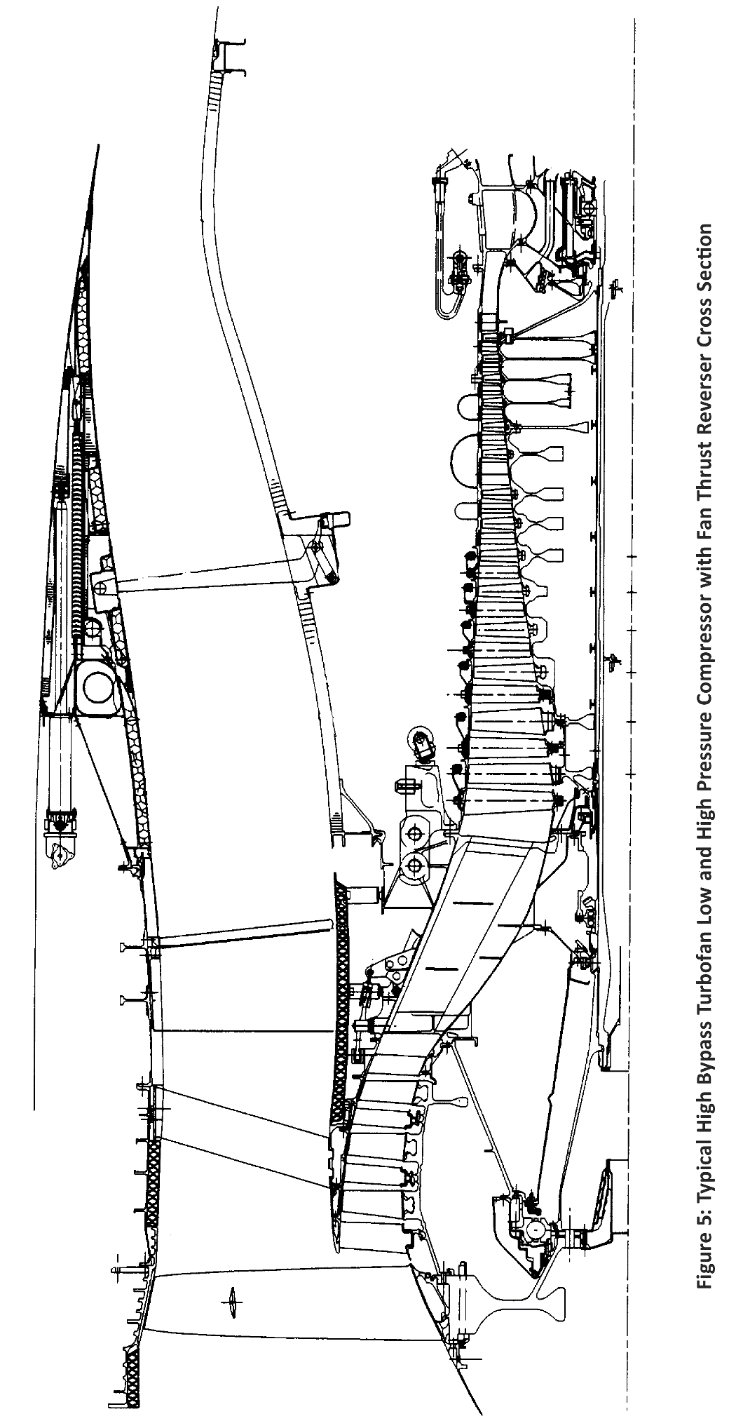
NOTE: See attached Figure 5: Typical High Bypass
Turbofan Low and High Pressure Compressor with Fan Thrust Reverser Cross
Section
(A) Large Fragments
For the
large fragments defined in Section 8.d.(4)(i)(A), above, the thrust reverser
retention systems should be redundant and separated as follows:
—
Ring
Disks Compressor Spools:
Retention
systems located in the outer barrel section of the thrust reverser should be
separated circumferentially (circumferential distance greater than the 1/3
disk fragment model as described in AMC20 128A) or axially (outside the * 5
degree impact area) so that a 1/3 disk segment can not damage all redundant
retention elements and allow thrust reversal (i.e., deployment of a door or
translating reverser sleeve half). Retention systems located between the inner
fan flow path wall and the engine casing should be located axially outside the
+ 5 degree impact area.
—
Deep-bore
Disk Spools and Single Disks:
Retention
systems should be separated axially with at least one retention element
located outside the * 5 degree impact area.
(B) Small Fragments
For the
small fragments defined in Section 8.d.(4)(i)(B), above, thrust reverser
retention systems should be provided with either:
—
At
least one retention element shielded in accordance with AMC 20-128A, paragraph
7(c), or capable of maintaining its retention capabilities after impact; or
—
One
retention element located outside the * 15 degree impact area.
9. «MIXED
CONTROLLABILITY / RELIABILITY» OPTION.
If the
aeroplane might experience an unwanted in-flight thrust reversal outside the
«controllable flight envelope» anytime during the entire operational life of
all aeroplanes of this type, then outside the controllable envelope
reliability compliance must be shown, taking into account associated risk
exposure time and the other considerations described in Section 8, above.
Conversely,
if reliability compliance is selected to be shown within a given limited
flight envelope with associated risk exposure time, then outside this envelope
controllability must be demonstrated taking into account the considerations
described in Section 7, above.
Mixed
controllability/reliability compliance should be shown in accordance with
guidance developed in Sections 7 and 8, above, respectively.
10. DEACTIVATED REVERSER.
The thrust
reverser system deactivation design should follow the same «fail-safe»
principles as the actuation system design, insofar as failure and
systems/hardware integrity. The effects
of thrust reverser system deactivation on other aeroplane systems, and on the
new configuration of the thrust reverser system itself, should be evaluated
according to Section 8.a., above. The location and load capability of the
mechanical lock-out system (thrust reverser structure and lock-out device)
should be evaluated according to Sections 8.b. and 8.d., above. The evaluation
should show that the level of safety associated with the deactivated thrust
reverser system is equivalent to or better than that associated with the
active system.
11. CS 25.933(b) COMPLIANCE.
For thrust
reversing systems intended for in-flight use, compliance with CS 25.933(b) may
be shown for unwanted in-flight thrust reversal, as appropriate, using the
methods specified in Sections 7 through 10, above.
12. CONTINUED AIRWORTHINESS.
12.a. Manufacturing/Quality: Due to the criticality of the thrust
reverser, manufacturing and quality assurance processes should be assessed and
implemented, as appropriate, to ensure the design integrity of the critical components.
12.b. Reliability Monitoring: An appropriate system should be implemented
for the purpose of periodic monitoring and reporting of in-service reliability
performance. The system should also
include reporting of in-service concerns related to design, quality, or
maintenance that have the potential of affecting the reliability of the thrust
reverser.
12.c. Maintenance and Alterations: The following material provides guidance for
maintenance designs and activity to assist in demonstrating compliance with
Sections 7 through 10, above (also reference CS 25.901(b)(2) and CS 25.1529/Appendix H). The criticality of the thrust
reverser and its control system requires that maintenance and maintainability
be emphasised in the design process and derivation of the maintenance control
program, as well as subsequent field maintenance, repairs, or alterations.
12.c.(1)
Design: Design aspects for providing adequate maintainability should address :
12.c.(1)(i)
Ease of maintenance. The following items should be taken into consideration:
—
It
should be possible to operate the thrust reverser for ground testing/trouble
shooting without the engine operating.
—
Lock-out
procedures (deactivation for flight) of the thrust reverser system should be
simple, and clearly described in the maintenance manual. Additionally, a
placard describing the procedure may be installed in a conspicuous place on
the nacelle.
—
Provisions
should be made in system design to allow easy and safe access to the
components for fault isolation, replacement, inspection, lubrication, etc. This
is particularly important where inspections are required to detect latent
failures. Providing safe access should
include consideration of risks both to the mechanic and to any critical design
elements that might be inadvertently damaged during maintenance.
—
Provisions
should be provided for easy rigging of the thrust reverser and adjustment of
latches, switches, actuators, etc.
12.c.(1)(ii)
Fault identification and elimination:
—
System
design should allow simple, accurate fault isolation and repair.
—
System
design personnel should be actively involved in the development,
documentation, and validation of the troubleshooting/fault isolation manual
and other maintenance publications. The systems design personnel should verify
that maintenance assumptions critical to any SSA conclusion are supported by
these publications (e.g., perform fault insertion testing to verify that the
published means of detecting, isolating, and eliminating the fault are
effective).
—
Thrust
reverser unstowed and unlocked indications should be easily discernible during
pre-flight inspections.
—
If
the aeroplane has onboard maintenance monitoring and recording systems, the
system should have provisions for storing all fault indications. This would be
of significant help to maintenance personnel in locating the source of
intermittent faults.
12.c.(1)(iii)
Minimisation of errors: Minimisation of errors during maintenance activity
should be addressed during the design process. Examples include physical
design features, installation orientation markings, dissimilar connections,
etc. The use of a formal «lessons learned»-based review early and often during
design development may help avoid repeating previous errors.
12.c.(1)(iv)
System Reliability: The design process should, where appropriate, use previous
field reliability data for specific and similar components to ensure system
design reliability.
12.c.(2) Maintenance Control:
12.c.(2)(i)
Maintenance Program: The development of the initial maintenance plan for the
aeroplane, including the thrust reverser, should consider, as necessary, the
following:
—
Involvement
of the manufacturers of the aeroplane, engine, and thrust reverser.
—
The
compatibility of the SSA information and the Maintenance Review Board Report,
Maintenance Planning Document, Master Minimum Equipment List, etc. (ref AMC 25.19).
—
Identification
by the manufacturer of all maintenance tasks critical to continued safe
flight. The operator should consider
these tasks when identifying and documenting Required Inspection Items.
—
The
complexity of lock-out procedures and appropriate verification.
—
Appropriate
tests, including an operational tests, of the thrust reverser to verify
correct system operation after the performance of any procedure that would
require removal, installation, or adjustment of a component; or disconnection
of a tube, hose, or electrical harness of the entire thrust reverser actuation
control system.
12.c.(2)(ii)
Training: The following considerations should be taken into account when
developing training documentation:
—
The
reason and the significance of accomplishing critical tasks as prescribed. This
would clarify why a particular task needs to be performed in a certain manner.
—
Instructions
or references as to what to do if the results of a check or operational test
do not agree with those given in the Aeroplane Maintenance Manual (AMM). The
manual should recommend some corrective action if a system fails a test or
check. This would help ensure that the
critical components are not overlooked in the trouble shooting process.
—
Emphasis
on the total system training by a single training source (preferably the
aeroplane manufacturer) to preclude fragmented information without a clear
system understanding. This training
concept should be used in the initial training and subsequent retraining.
—
Inclusion
of fault isolation and troubleshooting using the material furnished for the
respective manuals.
—
Evaluation
of the training materials to assure consistency between the training material
and the maintenance and troubleshooting manuals.
12.c.(2)(iii) Repairs and Alterations: The Instructions
for Continued Airworthiness essential to ensure that subsequent repairs or
alterations do not unintentionally violate the integrity of the original
thrust reverser system type design approval should be provided by the original
airframe manufacturer. Additionally, the original airframe manufacturer should
define a method of ensuring that this essential information will be evident to
those that may perform and approve such repairs and alterations. One example would be maintaining the wire
separation between relevant thrust reverser control electrical circuits. This
sensitivity could be communicated by statements in appropriate manuals such as
the Wiring Diagram Manual, and by decals or placards placed on visible areas
of the thrust reverser and/or aeroplane structure.
12.c.(2)(iv)
Feedback of Service Experience: The maintenance process should initiate the
feedback of service experience that will allow the monitoring of system
reliability performance and improvements in system design and maintenance
practices. Additionally, this service
experience should be used to assure the most current and effective formal
«lessons learned» design review process possible.
(A) Reliability Performance:
(Operators
and Manufacturers should collaborate on these items:)
—
Accurate
reporting of functional discrepancies.
—
Service
investigation of hardware by manufacturer to confirm and determine failure
modes and corrective actions if required.
—
Update
of failure rate data. (This will require co-ordination between the
manufacturers and airlines.)
(B) Improvements suggested by maintenance
experience:
(This will
provide data to effectively update these items:)
—
Manuals
—
Troubleshooting
—
Removal/replacement
procedures.
12.c.(2)(v)
Publications/Procedures: The following considerations should be addressed in
the preparation and revisions of the publications and procedures to support
the thrust reverser in the field in conjunction with CS 25.901(b)(2) and CS 25.1529(Appendix H).
(A) Documentation should be provided that
describes a rigging check, if required after adjustment of any thrust reverser
actuator drive system component.
(B) Documentation should be provided that
describes powered cycling of the thrust reverser to verify system integrity
whenever maintenance is performed. This
could also apply to any manual actuation of the reverser.
(C) The reasons and the significance of
accomplishing critical tasks should be included in the AMM.
(D) The AMM should include instructions or
references as to what to do if the results of a check or operational test do
not agree with those given in the AMM.
(E) Provisions should be made to address
inefficiencies and errors in the publications:
—
Identified
in the validation process of both critical and troubleshooting procedures.
—
Input
from field.
—
Operators
conferences.
(F) Development of the publications should be
a co-ordinated effort between the thrust reverser, engine, aeroplane
manufacturers and airline customers especially in the areas of:
—
AMM
—
Troubleshooting
—
Fault
isolation
—
Maintenance
data computer output
—
Procedure
Validation
—
Master
Minimum Equipment List
(G) Initial issue of the publication should
include the required serviceable limits for the complete thrust reverser
system.
13. FLIGHT CREW TRAINING.
In the case
of compliance with the «controllability option,» and when the nature of the
in-flight thrust reversal is judged as unusual (compared to expected
consequences on the aeroplane of other failures, both basic and recurrent),
flight crew training should be considered on a training simulator
representative of the aeroplane, that is equipped with thrust reverser
in-flight modelisation to avoid flight crew misunderstandings:
13.a. Transient manoeuvre: Recovery from the
unwanted in-flight thrust reversal.
13.b Continued flight and landing: Manoeuvring
appropriate to the recommended procedure (included trim and unattended
operation) and precision tracking (ILS guide slope tracking, speed/altitude
tracking, etc.).
Figure 4 - Generic Disk and Rotor
terminology used in interim thrust reverser guidance material for minimizing
the hazard from engine rotor burst
[Amdt No:
25/1]
[Amdt
No: 25/24]