AMC 25.1309 System design and analysis
ED
Decision 2021/015/R
Table
of Contents
1. PURPOSE
2. RESERVED
3. RELATED DOCUMENTS
a. Advisory Circulars,
Acceptable Means of Compliance
b. Industry Documents
4. APPLICABILITY OF CS
25.1309
5. DEFINITIONS
6. BACKGROUND
a. General
b. Fail-Safe Design Concept
c. Development of Aeroplane
and System Functions
7. FAILURE CONDITION
CLASSIFICATIONS AND PROBABILITY TERMS
a. Classifications
b. Qualitative Probability
Terms
c. Quantitative Probability
Terms
8. SAFETY OBJECTIVE
9. COMPLIANCE WITH CS
25.1309
a. Compliance with CS
25.1309(a)
b. Compliance with CS
25.1309(b)
(1) General
(2) Planning
(3) Availability of Industry
Standards and Guidance Materials
(4) Acceptable Application of
Development Assurance Methods
(5) Crew and Maintenance
Actions
(6) Significant Latent
Failures
c. Compliance with CS
25.1309(c)
10. IDENTIFICATION OF FAILURE
CONDITIONS AND CONSIDERATIONS WHEN ASSESSING THEIR EFFECTS
a. Identification of Failure
Conditions
b. Identification of Failure
Conditions Using a Functional Hazard Assessment
c. Considerations When
Assessing Failure Condition Effects
11. ASSESSMENT OF FAILURE
CONDITION PROBABILITIES AND ANALYSIS CONSIDERATIONS
a. Assessment of Failure
Condition Probabilities
b. Single Failure
Considerations
c. Common-Cause Failure
Considerations
d. Depth of Analysis
e. Calculation of Average
Probability per Flight Hour (Quantitative Analysis)
f. Integrated Systems
g. Operational or
Environmental Conditions
h. Justification of
Assumptions, Data Sources and Analytical Techniques
12. OPERATIONAL AND
MAINTENANCE CONSIDERATIONS
a. Flight Crew Action
b. Maintenance Action
c. Candidate Certification
Maintenance Requirements
d. Flight with Equipment or
Functions known to be Inoperative
13. ASSESSMENT OF
MODIFICATIONS TO PREVIOUSLY CERTIFIED AEROPLANES
APPENDIX 1. ASSESSMENT METHODS
APPENDIX 2. SAFETY ASSESSMENT PROCESS OVERVIEW
APPENDIX 3. CALCULATION OF THE AVERAGE PROBABILITY PER FLIGHT HOUR
APPENDIX 4. ALLOWABLE PROBABILITIES
APPENDIX 5. EXAMPLE OF LIMIT LATENCY AND RESIDUAL PROBABILITY ANALYSIS
1. PURPOSE.
a. This AMC describes acceptable means for
showing compliance with the requirements of CS 25.1309.
These means are intended to provide guidance to supplement the engineering and
operational judgement that must form the basis of any compliance
demonstration.
b. The extent to which the more structured
methods and guidelines contained in this AMC should be applied is a function
of systems complexity and systems failure consequence. In general, the extent
and structure of the analyses required to show compliance with CS 25.1309 will be greater when the system is more complex and the effects of the
Failure Conditions are more severe. This AMC is not intended to require that
the more structured techniques introduced in this revision be applied where
traditional techniques have been shown to be acceptable for more traditional
systems designs. The means described in this AMC are not mandatory. Other
means may be used if they show compliance with CS 25.1309.
2. RESERVED.
3. RELATED DOCUMENTS.
The
following guidance and advisory materials are referenced herein:
a. Advisory Circulars,
Acceptable Means of Compliance.
(1) AMC 25.1322 Alerting Systems.
(2) AC 25.19/AMC 25.19
Certification Maintenance Requirements.
(3) AMC 20-115 Software Considerations for
Airborne Systems and Equipment Certification
(4) AMC 25.901(c) Safety Assessment of Powerplant
Installations.
b. Industry documents.
(1) RTCA, Inc., Document No. DO-160D/EUROCAE
ED-14G, Environmental Conditions and Test Procedures for Airborne Equipment.
(2) Society of Automotive Engineers (SAE)
Aerospace Recommended Practice (ARP) 4754A/EUROCAE ED-79A, Guidelines for
development of civil aircraft and systems.
(3) Society of Automotive Engineers (SAE)
Aerospace Recommended Practice (ARP) 4761, Guidelines and Methods for
Conducting the Safety Assessment Process on Civil Airborne Systems and
Equipment.
4. APPLICABILITY OF CS 25.1309.
Paragraph 25.1309 is
intended as a general requirement that should be applied to any equipment or
system as installed, in addition to specific systems requirements, except as
indicated below.
a. While CS 25.1309
does not apply to the performance and flight characteristics of Subpart B and
structural requirements of Subparts C and D, it does apply to any system on
which compliance with any of those requirements is based. For example, it does
not apply to an aeroplane's inherent stall characteristics or their
evaluation, but it does apply to a stall warning system used to enable
compliance with CS 25.207.
b. Jams of
flight control surfaces or pilot controls that are covered by CS 25.671(c)(3) are excepted from the
requirements of CS 25.1309(b)(1)(ii).
c. Certain single failures covered by CS 25.735(b)(1) are excepted from the requirements of CS 25.1309(b).
The reason concerns the brake system requirement that limits the effect of a
single failure to doubling the brake roll stopping distance. This requirement
has been shown to provide a satisfactory level of safety without the need to
analyse the particular circumstances and conditions under which the single
failure occurs.
d. The failure conditions covered by CS 25.810
and CS 25.812 are excepted from the requirements of CS 25.1309(b).
These failure conditions related to loss of function are associated with
varied evacuation scenarios for which the probability cannot be determined. It
has not been proven possible to define appropriate scenarios under which
compliance with CS 25.1309(b) can be demonstrated. It is therefore
considered more practical to require particular design features or specific
reliability demonstrations as described in CS 25.810
and CS 25.812. Traditionally, this approach has been found
to be acceptable.
e. The requirements of CS 25.1309
are generally applicable to engine, propeller, and propulsion system
installations. The specific applicability and exceptions are stated in CS 25.901(c).
f. Some systems and some functions already
receive an evaluation to show compliance with specific requirements for
specific failure conditions and, therefore, meet the intent of CS 25.1309 without the need for additional analysis for those specific failure conditions.
g. The safety assessment process should
consider all phases during flight and on ground when the aeroplane is in
service. While this includes the conditions associated with the pre-flight
preparation, embarkation and disembarkation, taxi phase, etc., it, therefore,
does not include periods of shop maintenance, storage, or other out-of-service
activities.
Where
relevant, the effects on persons other than the aeroplane occupants should be
taken into account when assessing failure conditions in compliance with CS
25.1309.
5. DEFINITIONS.
The
following definitions apply to the system design and analysis requirements of CS 25.1309
and the guidance material provided in this AMC. They should not be assumed to
apply to the same or similar terms used in other regulations or AMCs. Terms
for which standard dictionary definitions apply are not defined herein.
a. Analysis.
The terms "analysis" and "assessment" are used throughout.
Each has a broad definition and the two terms are to some extent
interchangeable. However, the term analysis generally implies a more specific,
more detailed evaluation, while the term assessment may be a more general or
broader evaluation but may include one or more types of analysis. In practice,
the meaning comes from the specific application, e.g., fault tree analysis,
Markov analysis, Preliminary System Safety Assessment, etc.
b. Assessment.
See the definition of analysis above.
c. At-Risk
Time. The period of time during which an item must fail in order to cause
the failure effect in question. This is usually associated with the final
fault in a fault sequence leading to a specific failure condition.
d. Average
Probability Per Flight Hour. For the purpose of this AMC, is a
representation of the number of times the subject Failure Condition is
predicted to occur during the entire operating life of all aeroplanes of the
type divided by the anticipated total operating hours of all aeroplanes of
that type (Note: The Average Probability Per Flight Hour is normally
calculated as the probability of a Failure Condition occurring during a
typical flight of mean duration divided by that mean duration).
e. Candidate
Certification Maintenance Requirements (CCMR). A periodic maintenance or
flight crew check may be used in a safety analysis to help demonstrate
compliance with CS 25.1309(b) for hazardous and catastrophic failure conditions.
Where such checks cannot be accepted as basic servicing or airmanship they
become Candidate Certification Maintenance Requirements (CCMRs). AMC 25.19 defines a method by which Certification Maintenance Requirements
(CMRs) are identified from the candidates. A CMR becomes a required periodic
maintenance check identified as an operating limitation of the type
certificate for the aeroplane.
f. Check.
An examination (e.g., an inspection or test) to determine the physical
integrity and/or functional capability of an item.
g. Complex.
A system is Complex when its operation, failure modes, or failure effects are
difficult to comprehend without the aid of analytical methods.
h. Complexity.
An attribute of functions, systems or items, which makes their operation,
failure modes, or failure effects difficult to comprehend without the aid of
analytical methods.
i. Conventional.
A system is considered to be Conventional if its functionality, the
technological means used to implement its functionality, and its intended
usage are all the same as, or closely similar to, that of previously approved
systems that are commonly-used.
j. Design
Appraisal. This is a qualitative appraisal of the integrity and safety of
the system design.
k. Development
Assurance. All those planned and systematic actions used to substantiate,
to an adequate level of confidence, that errors in requirements, design, and
implementation have been identified and corrected such that the system
satisfies the applicable certification basis.
l. Development Error. A mistake in
requirements, design, or implementation.
m. Error.
An omission or incorrect action by a crewmember or maintenance personnel, or a
development error (e.g. mistake in requirements determination, design, or
implementation).
n. Event.
An occurrence which has its origin distinct from the aeroplane, such as
atmospheric conditions (e.g. gusts, temperature variations, icing and
lightning strikes), runway conditions, conditions of communication,
navigation, and surveillance services, bird-strike, cabin and baggage fires.
The term is not intended to cover sabotage.
o. Exposure
Time. The period of time between the time when an item was last known to
be operating properly and the time when it will be known to be operating
properly again.
p. Failure.
An occurrence, which affects the operation of a component, part, or element
such that it can no longer function as intended, (this includes both loss of
function and malfunction). Note: Errors may cause Failures, but are not
considered to be Failures.
q. Failure
Condition. A condition having an effect on the aeroplane and/or its
occupants, either direct or consequential, which is caused or contributed to
by one or more failures or errors, considering flight phase and relevant
adverse operational or environmental conditions, or external events.
r. Installation
Appraisal. This is a qualitative appraisal of the integrity and safety of
the installation. Any deviations from normal, industry-accepted installation
practices, such as clearances or tolerances, should be evaluated, especially
when appraising modifications made after entry into service.
s. Item. A hardware or software element
having bounded and well-defined interfaces.
t. Latent
Failure. A failure is latent until it is made known to the flight crew or
maintenance personnel.
u. Qualitative.
Those analytical processes that assess system and aeroplane safety in an
objective, nonnumerical manner.
v. Quantitative.
Those analytical processes that apply mathematical methods to assess system
and aeroplane safety.
w. Redundancy.
The presence of more than one independent means for accomplishing a given
function or flight operation.
x. Significant
Latent Failure. A latent failure that would, in combination with one or
more specific failure(s) or event(s), result in a hazardous or catastrophic
failure condition.
y. System.
A combination of interrelated items arranged to perform one or more specific
functions.
6. BACKGROUND
a. General
For a number
of years aeroplane systems were evaluated to specific requirements, to the "ʽsingle
fault’" criterion, or to the fail-safe design concept. As
later-generation aeroplanes developed, more safety-critical functions were
required to be performed, which generally resulted in an increase in the
complexity of the systems designed to perform these functions. The potential
hazards to the aeroplane and its occupants which could arise in the event of
loss of one or more functions provided by a system or that system's
malfunction had to be considered, as also did the interaction between systems
performing different functions. This has led to the general principle that an
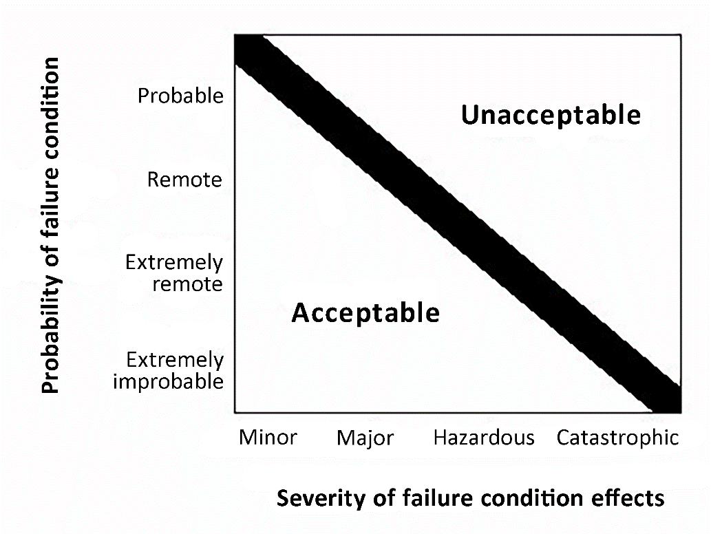
inverse relationship should exist between the probability of a failure
condition and its effect on the aeroplane and/or its occupants (see Figure 1).
In assessing the acceptability of a design it was recognised that rational
probability values would have to be established. Historical evidence indicated
that the probability of a serious accident due to operational and
airframe-related causes was approximately one per million hours of flight.
Furthermore, about 10 % of the total were attributed to failure
conditions caused by the aeroplane's systems. It seems reasonable that serious
accidents caused by systems should not be allowed a higher probability than
this in new aeroplane designs. It is reasonable to expect that the probability
of a serious accident from all such failure conditions be not greater than one
per ten million flight hours or 1 × 10⁻⁷ per flight hour for a
newly designed aeroplane. The difficulty with this is that it is not possible
to say whether the target has been met until all the systems on the aeroplane
are collectively analysed numerically. For this reason it was assumed, arbitrarily,
that there are about one hundred potential failure conditions in an aeroplane,
which could be Ccatastrophic. The target allowable average probability
per flight hour of 1 × 10⁻⁷ was thus apportioned equally among
these failure conditions, resulting in an allocation of not greater than 1 ×
10-9 to each. The upper limit for the average probability per
flight hour for catastrophic failure conditions would be 1 × 10⁻⁹,
which establishes an approximate probability value for the term ʽextremely
improbable’. Failure conditions having less severe effects could be relatively
more likely to occur.
b. Fail-Safe Design
Concept.
The CS-25
airworthiness standards are based on, and incorporate, the objectives and
principles or techniques of the fail-safe design concept, which considers the
effects of failures and combinations of failures in defining a safe design.
(1) The following basic objectives pertaining
to failures apply:
(i) In any system or subsystem, the failure
of any single element, component, or connection during any one flight should
be assumed, regardless of its probability. Such single failures should not be
catastrophic.
(ii) Subsequent failures of related systems
during the same flight, whether detected or latent, and combinations thereof,
should also be considered.
(2) The fail-safe design concept uses the
following design principles or techniques in order to ensure a safe design.
The use of only one of these principles or techniques is seldom adequate. A
combination of two or more is usually needed to provide a fail-safe design;
i.e. to ensure that major failure conditions are remote, hazardous failure
conditions are extremely remote, and catastrophic failure conditions are
extremely improbable:
(i) Designed
Integrity and Quality, including Life
Limits, to ensure intended function and prevent failures.
(ii) Redundancy
or Backup Systems to enable
continued function after any single (or other defined number of) failure(s);
e.g., two or more engines, hydraulic systems, flight control systems, etc.
(iii) Isolation
and/or Segregation of Systems, Components, and Elements so that the
failure of one does not cause the failure of another.
(iv) Proven
Reliability so that multiple, independent failures are unlikely to occur
during the same flight.
(v) Failure
Warning or Indication to provide detection.
(vi) Flight
crew Procedures specifying corrective action for use after failure
detection.
(vii) Checkability:
the capability to check a component's condition.
(viii) Designed
Failure Effect Limits, including the capability to sustain damage, to
limit the safety impact or effects of a failure.
(ix) Designed
Failure Path to control and direct the effects of a failure in a way that
limits its safety impact.
(x) Margins
or Factors of Safety to allow for any undefined or unforeseeable adverse
conditions.
(xi) Error-Tolerance
that considers adverse effects of foreseeable errors during the aeroplane's
design, test, manufacture, operation, and maintenance.
c. Development of Aeroplane and System
Functions.
(1) A concern arose regarding the efficiency
and coverage of the techniques used for assessing safety aspects of aeroplane
and systems functions implemented through the use of electronic technology and
software-based techniques. The concern is that design and analysis techniques
traditionally applied to deterministic risks or to conventional, non-complex
systems may not provide adequate safety coverage for these aeroplane and
system functions. Thus, other assurance techniques, such as development
assurance utilising a combination of integral processes (e.g. process
assurance, configuration management, requirement validation and implementation
verification), or structured analysis or assessment techniques applied at the
aeroplane level and across integrated or interacting systems, have been
requested. Their systematic use increases confidence that development errors
and integration or interaction effects have been adequately identified and
corrected.
(2) Considering the above developments, as
well as revisions made to the CS 25.1309, this AMC was revised to include
new approaches, both qualitative and quantitative, which may be used to assist
in determining safety requirements and establishing compliance with these
requirements, and to reflect revisions in the rule, considering the whole
aeroplane and its systems. It also provides guidance for determining when, or
if, particular analyses or development assurance actions should be conducted
in the frame of the development and safety assessment processes. Numerical
values are assigned to the probabilistic terms included in the requirements
for use in those cases where the impact of system failures is examined by
quantitative methods of analysis. The analytical tools used in determining
numerical values are intended to supplement, but not replace, qualitative
methods based on engineering and operational judgement.
7. FAILURE CONDITION
CLASSIFICATIONS AND PROBABILITY TERMS
a. Classifications.
Failure
conditions may be classified according to the severity of their effects as
follows:
(1) No
Safety Effect: Failure conditions that would have no effect on safety; for
example, failure conditions that would not affect the operational capability
of the aeroplane or increase crew workload.
(2) Minor:
Failure conditions which would not significantly reduce aeroplane safety, and
which involve crew actions that are well within their capabilities. Minor
failure conditions may include, for example, a slight reduction in safety
margins or functional capabilities, a slight increase in crew workload, such
as routine flight plan changes, or some physical discomfort to passengers or
cabin crew.
(3) Major:
Failure conditions which would reduce the capability of the aeroplane or the
ability of the crew to cope with adverse operating conditions to the extent
that there would be, for example, a significant reduction in safety margins or
functional capabilities, a significant increase in crew workload or in
conditions impairing crew efficiency, or discomfort to the flight crew, or
physical distress to passengers or cabin crew, possibly including injuries.
(4) Hazardous:
Failure conditions, which would reduce the capability of the aeroplane
or the ability of the crew to cope with adverse operating, conditions
to the extent that there would be:
(i) A large reduction in safety margins or
functional capabilities;
(ii) Physical distress or excessive workload
such that the flight crew cannot be relied upon to perform their tasks
accurately or completely; or
(iii) Serious or fatal injury to a relatively
small number of the occupants other than the flight crew.
(5) Catastrophic:
Failure conditions, which would result in multiple fatalities, usually
with the loss of the aeroplane.
(Note: A
failure condition which would prevent continued safe flight and landing should
be classified catastrophic unless otherwise defined in other specific AMCs.
For flight control systems, continued safe flight and landing is defined in AMC 25.671, paragraphs 4 and 7.)
b. Qualitative Probability Terms.
When using
qualitative analyses to determine compliance with CS 25.1309(b),
the following descriptions of the probability terms used in CS 25.1309
and this AMC have become commonly accepted as aids to engineering judgement:
(1) Probable failure conditions are those
anticipated to occur one or more times during the entire operational life of
each aeroplane.
(2) Remote failure conditions are those
unlikely to occur to each aeroplane during its total life, but which may occur
several times when considering the total operational life of a number of
aeroplanes of the type.
(3) Extremely remote failure conditions are
those not anticipated to occur to each aeroplane during its total life but
which may occur a few times when considering the total operational life of all
aeroplanes of the type.
(4) Extremely improbable failure conditions
are those so unlikely that they are not anticipated to occur during the entire
operational life of all aeroplanes of one type.
c. Quantitative Probability Terms.
When using
quantitative analyses to help determine compliance with CS 25.1309(b),
the following descriptions of the probability terms used in this requirement
and this AMC have become commonly accepted as aids to engineering judgement.
They are expressed in terms of acceptable ranges for the average probability
per flight hour.
(1) Probability Ranges.
(i) Probable failure conditions are those
having average probability per flight hour greater than of the order of 1 × 10⁻⁵.
(ii) Remote failure conditions are those having
an average probability per flight hour of the order of 1 × 10⁻⁵ or
less, but greater than of the order of 1 × 10⁻⁷.
(iii) Extremely remote failure conditions are
those having an average probability per flight hour of the order of 1 × 10⁻⁷
or less, but greater than of the order of 1 × 10⁻⁹.
(iv) Extremely improbable failure conditions
are those having an average probability per flight hour of the order of 1 × 10⁻⁹
or less.
8. SAFETY OBJECTIVE.
a. The objective of CS 25.1309
is to ensure an acceptable safety level for equipment and systems as installed
on the aeroplane. A logical and acceptable inverse relationship must exist
between the average probability per
flight hour and the severity of failure
condition effects, as shown in Figure 1, such that:
(1) Failure conditions with no safety effect have no probability requirement.
(2) Minor failure conditions may be probable.
(3) Major failure conditions must be no more frequent than remote.
(4) Hazardous failure conditions must be no more frequent than extremely
remote.
(5) Catastrophic failure conditions must be extremely improbable.
Figure
1: Relationship between Probability and Severity of Failure Condition Effects
b. The classification of the failure conditions
associated with the severity of their effects are described in Figure 2a.
The safety objectives associated with failure
conditions are described in Figure 2b.
Figure 2a: Relationship Between Severity of the
Effects and Classification of Failure Conditions
|
Severity of the Effects |
Effect on Aeroplane |
No effect on operational capabilities or
safety |
Slight reduction in functional
capabilities or safety margins |
Significant reduction in functional
capabilities or safety margins |
Large reduction in functional
capabilities or safety margins |
Normally with hull loss |
|
Effect on Occupants excluding Flight
Crew |
Inconvenience |
Physical discomfort |
Physical distress, possibly including
injuries |
Serious or fatal injury to a small
number of passengers or cabin crew |
Multiple fatalities |
|
|
Effect on Flight Crew |
No effect on flight crew |
Slight increase in workload |
Physical discomfort or a significant
increase in workload |
Physical distress or excessive workload
impairs ability to perform tasks |
Fatalities or incapacitation |
|
|
Classification of Failure Conditions |
No Safety Effect |
Minor |
Major |
Hazardous |
Catastrophic |
|
Figure 2b: Relationship Between Classification of
Failure Conditions and Probability
|
Classification of Failure Conditions |
No Safety Effect |
Minor |
Major |
Hazardous |
Catastrophic |
|
Allowable Qualitative Probability |
No Probability Requirement |
<-Probable-> |
<--Remote--> |
Extremely <--------------> Remote |
Extremely Improbable |
|
Allowable Quantitative Probability:
Average Probability per Flight Hour on the Order of: |
No Probability Requirement |
<--------------> <10-3 Note 1 |
<--------------> <10-5 |
<--------------> <10-7 |
<10-9 |
|
Note 1: A numerical probability range is provided
here as a reference. The applicant is not required to perform a quantitative
analysis, nor substantiate by such an analysis, that this numerical criteria
has been met for Minor Failure Conditions. Current transport category
aeroplane products are regarded as meeting this standard simply by using
current commonly‑accepted industry practice. |
|||||
c. The safety objectives associated with
catastrophic failure conditions must
be satisfied by demonstrating that:
(1) No single failure will result in a
catastrophic failure condition;
and
(2) Each catastrophic failure condition is extremely improbable; and
(3) Given that a single latent failure has
occurred on a given flight, each catastrophic failure condition, resulting
from two failures, either of which is latent for more than one flight, is
remote.
9. COMPLIANCE WITH CS 25.1309.
This
paragraph describes specific means of compliance for CS 25.1309.
The applicant should obtain early concurrence of the certification authority
on the choice of an acceptable means of compliance.
a. Compliance with CS 25.1309(a).
(1) Equipment covered by CS 25.1309(a)(1) must
be shown to function properly when installed. The aeroplane operating and
environmental conditions over which proper functioning of the equipment,
systems, and installation is required to be considered includes the full
normal envelope of the aeroplane as defined by the Aeroplane Flight Manual
operating limitations together with any modification to that envelope
associated with abnormal or emergency procedures. Other external environmental
conditions such as atmospheric turbulence, HIRF, lightning, and precipitation,
which the aeroplane is reasonably expected to encounter, should also be
considered. The severity of the external environmental conditions, which
should be considered, are limited to those established by certification
standards and precedence.
(2) In addition to the external operating and
environmental conditions, the effect of the environment within the aeroplane
should be considered. These effects should include vibration and acceleration
loads, variations in fluid pressure and electrical power, fluid or vapour
contamination, due either to the normal environment or accidental leaks or
spillage and handling by personnel. Document referenced in paragraph 3b(1)
defines a series of standard environmental test conditions and procedures,
which may be used to support compliance. Equipment covered by (CS) Technical
Standard Orders containing environmental test procedures or equipment
qualified to other environmental test standards can be used to support
compliance. The conditions under which the installed equipment will be
operated should be equal to or less severe than the environment for which the
equipment is qualified.
(3) The required substantiation of the proper
functioning of equipment, systems, and installations under the operating and
environmental conditions approved for the aeroplane may be shown by test
and/or analysis or reference to comparable service experience on other
aeroplanes. It must be shown that the comparable service experience is valid
for the proposed installation. For the equipment systems and installations
covered by CS 25.1309(a)(1), the compliance demonstration
should also confirm that the normal functioning of such equipment, systems,
and installations does not interfere with the proper functioning of other
equipment, systems, or installations covered by CS 25.1309(a)(1).
(4) The equipment, systems, and installations
covered by CS 25.1309(a)(2) are typically those
associated with amenities for passengers such as passenger entertainment
systems, in-flight telephones, etc., whose failure or improper functioning in
itself should not affect the safety of the aeroplane. Operational and
environmental qualification requirements for those equipment, systems, and
installations are reduced to the tests that are necessary to show that their
normal or abnormal functioning does not adversely affect the proper
functioning of the equipment, systems, or installations covered by CS
25.1309(a)(1) and does not otherwise adversely influence the safety of the
aeroplane or its occupants. Examples of adverse influences are: fire,
explosion, exposing passengers to high voltages, etc. Normal installation
practices should result in sufficiently obvious isolation so that
substantiation can be based on a relatively simple qualitative installation
evaluation. If the possible impacts, including failure modes or effects, are
questionable, or isolation between systems is provided by complex means, more
formal structured evaluation methods may be necessary.
b. Compliance with CS 25.1309(b).
Paragraph 25.1309(b)
requires that the aeroplane systems and associated components, considered
separately and in relation to other systems, must be designed so that any
catastrophic failure condition
is extremely improbable and does not result from a single failure. It also
requires that any hazardous failure
condition is extremely remote, and that any major failure condition is remote. An
analysis should always consider the application of the fail-safe design
concept described in paragraph 6.b, and give special attention to ensuring the
effective use of design techniques that would prevent single failures or other
events from damaging or otherwise adversely affecting more than one redundant
system channel or more than one system performing operationally similar
functions.
(1) General.
Compliance with the requirements of CS 25.1309(b) should be shown by analysis and,
where necessary, by appropriate ground, flight, or simulator tests. Failure conditions should be identified and
their effects assessed. The maximum allowable probability of the occurrence of
each failure condition is
determined from the failure condition’s
effects, and when assessing the probabilities of failure conditions, appropriate analysis considerations should be
accounted for. Any analysis must consider:
(i)
Possible failure conditions and
their causes, modes of failure, and damage from sources external to the
system.
(ii) The possibility of multiple failures and
undetected failures.
(iii) The possibility of requirement, design and
implementation errors.
(iv) The effect of reasonably anticipated crew
errors after the occurrence of a failure or failure condition.
(v) The effect of reasonably anticipated
errors when performing maintenance actions.
(vi) The crew alerting cues, corrective action
required, and the capability of detecting faults.
(vii) The resulting effects on the aeroplane and
occupants, considering the stage of flight, the sequence of events/failures
occurrence when relevant, and operating and environmental conditions.
(2) Planning. This
AMC provides guidance on methods of accomplishing the safety objective. The
detailed methodology needed to achieve this safety objective will depend on
many factors, in particular the degree of systems complexity and integration.
For aeroplanes containing many complex or integrated systems, it is likely
that a plan will need to be developed to describe the intended process. This
plan should include consideration of the following aspects:
(i) Functional and physical
interrelationships of systems.
(ii) Determination of detailed means of
compliance, which should include development assurance activities.
(iii) Means for establishing the accomplishment
of the plan.
(3) Availability
of Industry Standards and Guidance Materials. There are a variety of
acceptable techniques currently being used in industry, which may or may not
be reflected in the documents referenced in paragraphs 3.b(2) and 3.b(3). This
AMC is not intended to compel the use of these documents during the definition
of the particular method of satisfying the objectives of this AMC. However,
these documents do contain material and methods of performing the system
safety assessment. These methods, when correctly applied, are recognised by
EASA as valid for showing compliance with CS 25.1309(b). In addition, the Document referenced in paragraph 3.b(3) contains
tutorial information on applying specific engineering methods (e.g. Markov
analysis, fault tree analysis) that may be utilised in whole or in part.
(4) Acceptable
Application of Development Assurance Methods. Paragraph 9.b(1)(iii) above
requires that any analysis necessary to demonstrate compliance with CS 25.1309(b)
must consider the possibility of development errors. Errors made during the
design and development of systems have traditionally been detected and
corrected by exhaustive tests conducted on the system and its components, by
direct inspection, and by other direct verification methods capable of
completely characterising the performance of the system. These direct
techniques may still be appropriate for systems containing non-complex items
(i.e. items that are fully assured by a combination of testing and analysis)
that perform a limited number of functions and that are not highly integrated
with other aeroplane systems. For more complex or integrated systems,
exhaustive testing may either be impossible because all of the system states
cannot be determined or impractical because of the number of tests that must
be accomplished. For these types of systems, compliance may be demonstrated by
the use of development assurance. The level of development assurance (function
development assurance level (FDAL)/item development assurance level (IDAL))
should be commensurate with the severity of the failure conditions the system is contributing to.
Guidelines,
which may be used for the assignment of development assurance levels to
aeroplanes and system functions (FDAL) and to items (IDAL), are described in
the Document referenced in 3.b(2) above. Through this Document, EASA
recognises that credit can be taken from system architecture (e.g. functional
or item development independence) for the FDAL/IDAL assignment process.
Guidelines,
which may be used for providing development assurance, are described for
aeroplane and system development in the Document referenced in 3.b(2), and for
software in the Document referenced in 3.a(3) above. (There is currently no
agreed development assurance standard for airborne electronic hardware.)
(5) Crew and Maintenance
Actions.
(i) Where an analysis identifies some
indication to, and/or action by, the flight crew, cabin crew, or maintenance
personnel, the following activities should be accomplished:
1 Verify that any identified indications
are actually provided by the system. This includes the verification that the
elements that provide detection (e.g. sensors, logic) properly trigger the
indication under the relevant situations considering various causes, flight
phases, operating conditions, operational sequences, and environments.
2 Verify that any identified indications
will, in fact, be recognised.
3 Verify that any actions required have a
reasonable expectation of being accomplished successfully and in a timely
manner.
(ii) These verification activities should be
accomplished by consulting with engineers, pilots, flight attendants,
maintenance personnel, and human factors specialists, as appropriate, taking
due consideration of any relevant service experience and the consequences if
the assumed action is not performed or performed improperly.
(iii) In complex situations, the results of the
review by specialists may need to be confirmed by simulator, ground tests, or
flight tests. However, quantitative assessments of the probabilities of crew
or maintenance errors are not currently considered feasible. If the failure
indications are considered to be recognisable and the required actions do not
cause an excessive workload, then for the purposes of the analysis, such
corrective actions can be considered to be satisfactorily accomplished. If the
necessary actions cannot be satisfactorily accomplished, the tasks and/or the
systems need to be modified.
(6) Significant Latent
Failures.
(i) Compliance with CS 25.1309(b)(4)
For
compliance with CS 25.1309(b)(4), the hereafter systematic approach should be
followed:
1. The applicant must first eliminate
significant latent failures to the maximum practical extent utilising the
current state-of-the-art technology, e.g. implement practical and reliable
failure monitoring and flight crew indication systems to detect failures that
would otherwise be latent for more than one flight. Additional guidance is
provided in AMC 25-19 Section 8, Design Considerations Related to
Significant Latent Failures.
2. For each significant latent failure
which cannot reasonably be eliminated, the applicant must minimise the
exposure time by design utilising current state-of-the-art technology rather
than relying on scheduled maintenance tasks at lengthy intervals, i.e.
implementing pilot-initiated checks, or self-initiated checks (e.g. first
flight of the day check, power-up built-in tests, other system automated
checks).
3. When relying on scheduled maintenance
tasks, quantitative as well as qualitative aspects need to be addressed when
limiting the latency. Additional guidance is provided in AMC 25-19
Section 10, Identification of Candidate CMRs (CCMRs).
Note: For
turbojet thrust reversing systems, the design configurations in paragraphs
8.b(2) and 8.b(3) of AMC 25.933(a)(1) have traditionally been considered
to be acceptable to EASA for compliance with CS 25.1309(b)(4).
(ii) Compliance with CS 25.1309(b)(5)
When a catastrophic failure condition
involves two failures, either one of which is latent for more than one flight,
and cannot reasonably be eliminated, compliance with CS 25.1309(b)(5) is
required. Following the proper application of CS 25.1309(b)(4), the
failure conditions involving multiple significant latent failures are expected
to be sufficiently unlikely such that the dual-failure situations addressed in
CS 25.1309(b)(5) are the only remaining significant latent failures of
concern.
These significant latent failures of
concern should be highlighted to EASA as early as possible. The system safety
assessment should explain why avoidance is not practical, and provide
supporting rationale for the acceptability. Rationale should be based on the
proposed design being state-of-the-art, past experience, sound engineering
judgment, or other arguments, which led to the decision not to implement other
potential means of avoidance (e.g. eliminating the significant latent failure
or adding redundancy).
Two criteria are implemented in CS 25.1309(b)(5): limit latency and limit residual probability.
Limit
latency is intended to limit the time of operating with one evident failure
away from a catastrophic failure condition. This is achieved by requiring that
the sum of the probabilities of the latent failures, which are combined with
each evident failure, does not exceed 1/1 000. Taking one catastrophic
failure condition at a time,
—
in
case an evident failure is combined only once in a dual failure combination of
concern, the probability of the individual latent failure needs to comply with
the 1/1 000 criterion;
—
in
case an evident failure is combined in multiple dual failure combinations of
concern, the combined probabilities of the latent failures need to comply with
the 1/1 000 criterion.
Limit
residual probability is intended to limit the average probability per flight
hour of the failure condition given the presence of a single latent failure.
This is achieved by defining the residual probability to be ‘remote’. Residual
probability is the combined average probability per flight hour of all the
single active failures that result in the catastrophic failure condition
assuming one single latent failure has occurred.
These
requirements are applied in addition to CS 25.1309(b)(1), which requires
that catastrophic failure conditions be shown to be extremely improbable and
do not result from a single failure.
Appendix 5
provides simplified examples explaining how the limit latency and limit
residual probability analysis might be applied.
For
compliance with the 1/1 000 criterion, the probability of the latent
failures of concern should be derived from the probability of the worst-case
flight, i.e. the probability where the evident failure occurs in the last
flight before the scheduled maintenance inspection, while the latent failure
may have occurred in any flight between two consecutive scheduled maintenance
inspections. When dealing with constant failure rates, the probability of the
latent failure should be computed as the product of the maximum time during
which the failure may be present (i.e. exposure time) and its failure rate, if
this probability is less than or equal to 0.1.
c. Compliance with CS 25.1309(c).
CS 25.1309(c) requires that information
concerning unsafe system operating conditions must be provided to the crew to
enable them to take appropriate corrective action in a timely manner, thereby
mitigating the effects to an acceptable level. Any system operating condition
that, if not detected and properly accommodated by flight crew action, would
contribute to or cause a hazardous or catastrophic failure condition should be
considered to be an ‘unsafe system operating condition’. Compliance with this
requirement is usually demonstrated by the analysis identified in paragraph
9.b(1) above, which also includes consideration of crew alerting cues,
corrective action required, and the capability of detecting faults. The
required information may be provided by dedicated indication and/or
annunciation or made apparent to the flight crew by the inherent
aeroplane/systems responses. When flight crew alerting is required, it must be
provided in compliance with CS 25.1322. CS 25.1309(c) also requires
that installed systems and equipment
for use by the flight crew, including flight deck controls and information, be
designed to minimise flight crew errors that could create additional hazards
(in compliance with CS 25.1302).
(1) The required information will depend on
the degree of urgency for recognition and corrective action by the crew. It
should be in the form of:
(i) a warning, if immediate recognition and
corrective or compensatory action by the crew is required;
(ii) a caution if immediate crew awareness is
required and subsequent crew action will be required;
(iii) an advisory, if crew awareness is required
and subsequent crew action may be required;
(iv) a message in the other cases.
CS 25.1322 (and AMC 25.1322) give further requirements (and
guidance) on the characteristics of the information required (visual, aural)
based on those different categories.
(2) When failure monitoring and indication are
provided by a system, its reliability should be compatible with the safety
objectives associated with the system function for which it provides that
indication. For example, if the effects of having a system failure and not
annunciating that system failure are catastrophic, the combination of the
system failure with the failure of its annunciation must be extremely
improbable. The loss of annunciation itself should be considered a failure
condition, and particular attention should be paid to the impact on the
ability of the flight crew to cope with the subject system failure. In
addition, unwanted operation (e.g. nuisance warnings) should be assessed. The
failure monitoring and indication should be reliable, technologically
feasible, and economically practical. Reliable failure monitoring and
indication should utilise current state-of-the-art technology to maximise the
probability of detecting and indicating genuine failures while minimising the
probability of falsely detecting and indicating non-existent failures. Any
indication should be timely, obvious, clear, and unambiguous.
(3) In the case of aeroplane conditions
requiring immediate crew action, a suitable warning indication must be
provided to the crew, if not provided by inherent aeroplane characteristics.
In either case, any warning should be rousing and should occur at a point in a
potentially catastrophic sequence where the aeroplane's capability and the
crew's ability still remain sufficient for effective crew action.
(4) Unless they are accepted as normal
airmanship, procedures for the crew to follow after the occurrence of failure
warning should be described in the approved Aeroplane Flight Manual (AFM) or
AFM revision or supplement.
(5) Even if operation or performance is
unaffected or insignificantly affected at the time of failure, information to
the crew is required if it is considered necessary for the crew to take any
action or observe any precautions. Some examples include reconfiguring a
system, being aware of a reduction in safety margins, changing the flight plan
or regime, or making an unscheduled landing to reduce exposure to a more
severe failure condition that
would result from subsequent failures or operational or environmental
conditions. Information is also required if a failure must be corrected before
a subsequent flight. If operation or performance is unaffected or
insignificantly affected, information and alerting indications may be
inhibited during specific phases of flight where corrective action by the crew
is considered more hazardous than no action.
(6) The use of periodic maintenance or flight
crew checks to detect significant latent failures when they occur is
undesirable and should not be used in lieu of practical and reliable failure
monitoring and indications. When this is not accomplished, refer to paragraph
9.b(6) for guidance.
Paragraph 12
provides further guidance on the use of periodic maintenance or flight crew
checks. Comparison with similar, previously approved systems is sometimes
helpful. However, if a new technical solution allows practical and reliable
failure monitoring and indications, this should be preferred in lieu of
periodic maintenance or flight crew checks.
(7) Particular attention should be given to
the placement of switches or other control devices, relative to one another,
so as to minimise the potential for inadvertent incorrect crew action,
especially during emergencies or periods of high workload. Extra protection,
such as the use of guarded switches, may sometimes be needed.
10. IDENTIFICATION OF FAILURE
CONDITIONS AND CONSIDERATIONS WHEN ASSESSING THEIR EFFECTS.
a. Identification of
Failure Conditions.
Failure
conditions should be identified by considering the potential effects of
failures on the aeroplane and occupants. These should be considered from two
perspectives:
(1) by considering failures of aeroplane-level
functions — failure conditions
identified at this level are not dependent on the way the functions are
implemented and the systems' architecture.
(2) by considering failures of functions at
the system level — these failure
conditions are identified through examination of the way that functions
are implemented and the systems' architectures. It should be noted that a failure condition might result from a
combination of lower-level failure
conditions. This requires that the analysis of complex, highly
integrated systems, in particular, should be conducted in a highly methodical
and structured manner to ensure that all significant failure conditions, that arise from multiple failures and
combinations of lower-level failure
conditions, are properly identified and accounted for. The relevant
combinations of failures and failure
conditions should be determined by the whole safety assessment process
that encompasses the aeroplane and system level functional hazard assessments
and common-cause analyses. The overall effect on the aeroplane of a
combination of individual system failure
conditions occurring as a result of a common or cascade failure, may be
more severe than the individual system effect. For example, failure conditions classified as
minor or major by themselves may have hazardous effects at an aeroplane level,
when considered in combination.
b. Identification of
Failure Conditions Using a Functional Hazard Assessment.
(1) Before a detailed safety assessment is
proceeded with, a functional hazard assessment (FHA) of the aeroplane and
system functions to determine the need for and scope of subsequent analysis
should be prepared. This assessment may be conducted using service experience,
engineering and operational judgement, and/or a top-down deductive qualitative
examination of each function. An FHA is a systematic, comprehensive
examination of aeroplane and system functions to identify potential minor,
major, hazardous, and catastrophic failure
conditions that may arise, not only as a result of malfunctions or
failure to function, but also as a result of normal responses to unusual or
abnormal external factors. It is concerned with the operational
vulnerabilities of systems rather than with a detailed analysis of the actual
implementation.
(2) Each system function should be examined
with respect to the other functions performed by the system, because the loss
or malfunction of all functions performed by the system may result in a more
severe failure condition than the loss of a single function. In addition, each
system function should be examined with respect to functions performed by
other aeroplane systems, because the loss or malfunction of different but
related functions, provided by separate systems may affect the severity of
Failure Conditions postulated for a particular system.
(3) The FHA is an engineering tool, which
should be performed early in the design and updated as necessary. It is used
to define the high-level aeroplane or system safety objectives that must be
considered in the proposed system architectures. It should also be used to
assist in determining the development assurance levels for the systems. Many
systems may need only a simple review of the system design by the applicant to
determine the hazard classification. An FHA requires experienced engineering
judgement and early co-ordination between the applicant and the certification
authority.
(4) Depending on the extent of functions to be
examined and the relationship between functions and systems, different
approaches to FHA may be taken. Where there is a clear correlation between
functions and systems, and where system, and hence function, interrelationships
are relatively simple, it may be feasible to conduct separate FHAs for each
system, providing any interface aspects are properly considered and are easily
understood. Where system and function interrelationships are more complex, a
top-down approach, from an aeroplane-level perspective, should be taken in
planning and conducting FHAs However, with the increasing integrated system
architectures, this traditional top-down approach should be performed in
conjunction with common-cause considerations (e.g. common resources) in order
to properly address the cases where one system contributes to several
aeroplane-level functions.
c. Considerations When
Assessing Failure Condition Effects.
The
requirements of CS 25.1309(b) are intended to ensure an orderly and
thorough evaluation of the effects on safety of foreseeable failures or other
events, such as errors or external circumstances, separately or in
combination, involving one or more system functions. The interactions of these
factors within a system and among relevant systems should be considered.
In assessing
the effects of a failure condition,
factors which might alleviate or intensify the direct effects of the initial failure condition should be
considered. Some of these factors include consequent or related conditions
existing within the aeroplane that may affect the ability of the crew to deal
with direct effects, such as the presence of smoke, acceleration effects,
interruption of communication, interference with cabin pressurisation, etc.
When assessing the consequences of a given failure condition, account should be taken of the failure
information provided, the complexity of the crew action, and the relevant crew
training. The number of overall failure
conditions involving other than instinctive crew actions may influence
the flight crew performance that can be expected. Training recommendations may
need to be identified in some cases.
(1) The severity of failure conditions should be evaluated according to the
following:
(i) Effects on the aeroplane, such as
reductions in safety margins, degradation in performance, loss of capability
to conduct certain flight operations, reduction in environmental protection,
or potential or consequential effects on structural integrity. When the
effects of a failure condition are difficult to assess, the hazard
classification may need to be validated by tests, simulation, or other
appropriate analytical techniques.
(ii) Effects on the crewmembers, such as
increases above their normal workload that would affect their ability to cope
with adverse operational or environmental conditions or subsequent failures.
(iii) Effects on the occupants, i.e., passengers
and crewmembers.
(2) For convenience in conducting design
assessments, failure conditions
may be classified according to the severity of their effects as ‘no safety
effect’, ‘minor’, ‘major’, ‘hazardous’, or ‘catastrophic’. Paragraph 7.a above
provides accepted definitions of these terms.
(i) The classification of failure conditions does not depend on
whether or not a system or function is the subject of a specific requirement
or regulation. Some ʽrequired’ systems, such as transponders, position lights,
and public address systems, may have the potential for only minor failure conditions. Conversely, other
systems which are not ʽrequired’, such as auto-flight systems, may have the
potential for ‘major’, ‘hazardous’, or ‘catastrophic failure conditions’.
(ii) Regardless of the types of assessment
used, the classification of failure
conditions should always be accomplished with consideration of all
relevant factors; e.g., system, crew, performance, operational,
external. It is particularly important to consider factors that would
alleviate or intensify the severity of a failure condition. When flight duration, flight phase, or
diversion time can adversely affect the classification of failure conditions,
they must be considered to be intensifying factors. Other intensifying factors
include conditions that are not related to the failure (such as weather or
adverse operational or environmental conditions), and which reduce the ability
of the flight crew to cope with a failure condition. An example of an
alleviating factor would be the continued performance of identical or
operationally similar functions by other systems not affected by the failure condition. Another example of
an alleviating factor is the ability of the flight crew to recognise the
failure condition and take action to mitigate its effects. Whenever this is
taken into account, particular attention should be paid to the detection means
to ensure that the ability of the flight crew (including physical ability and
timeliness of the response) to detect the failure condition and take the
necessary corrective action(s) is sufficient. Refer to CS 25.1309(c) and paragraph 9.c of this AMC for more detailed guidance on crew
annunciations and crew response evaluation. Combinations of intensifying or
alleviating factors need to be considered only if they are anticipated to
occur together.
11. ASSESSMENT OF FAILURE
CONDITION PROBABILITIES AND ANALYSIS CONSIDERATIONS.
After the failure conditions have been
identified and the severity of the effects of the failure conditions have been assessed, there is a responsibility
to determine how to show compliance with the requirement and obtain the
concurrence of EASA. Design and installation reviews, analyses, flight tests,
ground tests, simulator tests, or other approved means may be used.
a. Assessment of Failure
Condition Probabilities.
(1) The probability that a failure condition would occur may be
assessed as probable, remote, extremely remote, or extremely improbable. These
terms are defined in paragraph 7. Each failure
condition should have a probability that is inversely related to the
severity of its effects as described in paragraph 8.
(2) When a system provides protection from
events (e.g., cargo compartment fire, gusts), its reliability should be
compatible with the safety objectives necessary for the failure condition associated with the
failure of the protection system and the probability of such events. (See
paragraph 11g of this AMC and Appendix 4.)
(3) An assessment to identify and classify failure conditions is necessarily
qualitative. On the other hand, an assessment of the probability of a failure condition may be either
qualitative or quantitative. An analysis may range from a simple report that
interprets test results or compares two similar systems to a detailed analysis
that may or may not include estimated numerical probabilities. The depth and
scope of an analysis depends on the types of functions performed by the
system, the severity of failure
conditions, and whether or not the system is complex.
(4) Experienced engineering and operational
judgement should be applied when determining whether or not a system is
complex. Comparison with similar, previously approved systems is sometimes
helpful. All relevant systems’ attributes should be considered; however, the
complexity of the software and hardware item need not be a dominant factor in
the determination of complexity at the system level.
b. Single Failure
Considerations.
(1) According to the requirements of CS 25.1309(b)(1)(ii), a catastrophic failure
condition must not result from the failure of a single component, part,
or element of a system. Failure containment should be provided by the system
design to limit the propagation of the effects of any single failure to
preclude catastrophic failure
conditions. In addition, there must be no common-cause failure, which
could affect both the single component, part, or element, and its failure
containment provisions. A single failure includes any set of failures, which
cannot be shown to be independent from each other. Common-cause failures
(including common mode failures) and cascading failures should be evaluated as
dependent failures from the point of the root cause or the initiator. Errors
in development, manufacturing, installation, and maintenance can result in
common-cause failures (including common mode failures) and cascading failures.
They should, therefore, be assessed and mitigated in the frame of the
common-cause and cascading failures consideration. Appendix 1 and the Document
referenced in paragraph 3.b(3) describe types of common-cause analyses that
may be conducted, to assure that independence is maintained. Failure
containment techniques available to establish independence may include
partitioning, separation, and isolation.
(2) While single failures must normally be
assumed to occur, there are cases where it is obvious that, from a realistic
and practical viewpoint, any knowledgeable, experienced person would
unequivocally conclude that a failure mode simply would not occur, unless it
is associated with a wholly unrelated failure
condition that would itself be catastrophic. Once identified and
accepted, such cases need not be considered failures in the context of CS 25.1309.
For example, with simply loaded static elements, any failure mode, resulting
from fatigue fracture, can be assumed to be prevented if this element is shown
to meet the damage tolerance requirements of CS 25.571.
c. Common Cause Failure
Considerations.
An analysis
should consider the application of the fail-safe design concept described in
paragraph 6b and give special attention to ensure the effective use of design
and installation techniques that would prevent single failures or other events
from damaging or otherwise adversely affecting more than one redundant system
channel, more than one system performing operationally similar functions, or
any system and an associated safeguard. When considering such common-cause
failures or other events, consequential or cascading effects should be taken
into account. Some examples of such potential common cause failures or other
events would include rapid release of energy from concentrated sources such as
uncontained failures of rotating parts (other than engines and propellers) or
pressure vessels, pressure differentials, non-catastrophic structural
failures, loss of environmental conditioning, disconnection of more than one
subsystem or component by over temperature protection devices, contamination
by fluids, damage from localised fires, loss of power supply or return (e.g.
mechanical damage or deterioration of connections), excessive voltage,
physical or environmental interactions among parts, errors, or events external
to the system or to the aeroplane (see Document referenced in paragraph 3b(3)).
d. Depth
of Analysis.
The
following identifies the depth of analysis expected based on the
classification of a failure condition.
(1) No
Safety Effect Failure Conditions. An FHA, with a design and installation
appraisal, to establish independence from other functions is necessary for the
safety assessment of these failure
conditions. If it is chosen not to do an FHA, the safety effects may be
derived from the design and installation appraisal.
(2) Minor
Failure Conditions. An FHA, with a design and installation appraisal, to
establish independence from other functions is necessary for the safety
assessment of these failure conditions.
Combinations of failure condition
effects, as noted in paragraph 10 above, must also be considered. If it is
chosen not to do an FHA, the safety effects may be derived from the design and
installation appraisal.
(3) Major
Failure Conditions. Major failure conditions must be remote:
(i) If the system is similar in its relevant
attributes to those used in other aeroplanes and the effects of failure would
be the same, then design and installation appraisals (as described in Appendix 1),
and satisfactory service history of the equipment being analysed, or of
similar design, will usually be acceptable for showing compliance.
(ii) For systems that are not complex, where
similarity cannot be used as the basis for compliance, then compliance may be
shown by means of a qualitative assessment that shows that the system-level
major failure conditions, of
the system as installed, are consistent with the FHA and are remote, e.g.
redundant systems.
(iii) For complex systems without redundancy,
compliance may be shown as in paragraph 11.d(3)(ii) of this AMC. To show that
malfunctions are indeed remote in systems of high complexity without
redundancy (for example, a system with a self-monitoring microprocessor), it
is sometimes necessary to conduct a qualitative functional failure modes and
effects analysis (FMEA) supported by failure rate data and fault detection
coverage analysis.
(iv) An analysis of a redundant system is
usually complete if it shows isolation between redundant system channels and
satisfactory reliability for each channel. For complex systems where
functional redundancy is required, a qualitative FMEA and qualitative fault
tree analysis may be necessary to determine that redundancy actually exists
(e.g. no single failure affects all functional channels).
(4) Hazardous
and Catastrophic Failure Conditions.
Hazardous failure conditions must be extremely
remote, and catastrophic failure conditions must be extremely improbable:
(i) Except as specified in paragraph
11.d(4)(ii) below, a detailed safety analysis will be necessary for each
hazardous and catastrophic failure
condition identified by the FHA. The analysis will usually be a
combination of qualitative and quantitative assessment of the design.
(ii) For very simple and conventional
installations, i.e. low complexity and similarity in relevant attributes, it
may be possible to assess a hazardous or catastrophic failure condition as being extremely remote or extremely
improbable, respectively, on the basis of experienced engineering judgement,
using only qualitative analysis. The basis for the assessment will be the
degree of redundancy, the established independence and isolation of the
channels and the reliability record of the technology involved. Satisfactory
service experience on similar systems commonly used in many aeroplanes may be
sufficient when a close similarity is established in respect of both the system
design and operating conditions.
(iii) For complex systems where true similarity
in all relevant attributes, including installation attributes, can be
rigorously established, it may be also possible to assess a hazardous or
catastrophic failure condition
as being extremely remote or extremely improbable, respectively, on the basis
of experienced engineering judgement, using only qualitative analysis. A high
degree of similarity in both design and application is required to be
substantiated.
e. Calculation of
Average Probability per Flight Hour (Quantitative Analysis).
(1) The average probability per flight hour is
the probability of occurrence, normalised by the flight time, of a failure condition during a flight,
which can be seen as an average over all possible flights of the fleet of
aeroplane to be certified. The calculation of the average probability per
flight hour for a failure condition
should consider:
(i) the average flight duration and the
average flight profile for the aeroplane type to be certified,
(ii) all combinations of failures and events
that contribute to the failure
condition,
(iii) the conditional probability if a sequence
of events is necessary to produce the failure
condition,
(iv) the relevant ʽat risk’ time if an event is
only relevant during certain flight phases, and
(v) the exposure time if the failure can
persist for multiple flights.
(2) The details how to calculate the average
probability per flight hour for a failure
condition are given in Appendix 3 of this AMC.
(3) If the probability of a subject failure condition occurring during a
typical flight of mean duration for the aeroplane type divided by the flight’s
mean duration in hours is likely to be significantly different from the
predicted average rate of occurrence of that failure condition during the entire operational life of all
aeroplanes of that type, then a risk model that better reflects the failure condition should be used.
(4) It is recognised that, for various
reasons, component failure rate data are not precise enough to enable accurate
estimates of the probabilities of failure
conditions. This results in some degree of uncertainty, as indicated by
the wide line in Figure 1, and the expression ʽon the order of’ in the
descriptions of the quantitative probability terms that are provided above.
When calculating the estimated probability of each failure condition, this uncertainty should be accounted for in a
way that does not compromise safety.
f. Integrated
Systems.
Interconnections
between systems have been a feature of aeroplane design for many years and CS 25.1309(b)
recognises this in requiring systems to be considered in relation to other
systems. Providing the interfaces between systems are relatively few and
simple, and hence readily understandable, compliance may often be demonstrated
through a series of system safety assessments, each of which deals with a
particular failure condition
(or more likely a group of failure
conditions) associated with a system and, where necessary, takes
account of failures arising at the interface with other systems. This
procedure has been found to be acceptable in many past certification
programmes. However, where the systems and their interfaces become more
complex and extensive, the task of demonstrating compliance may become more
complex. It is therefore essential that the means of compliance be considered
early in the design phase to ensure that the design can be supported by a
viable safety assessment strategy. Aspects of the guidance material covered
elsewhere in this AMC and which should be given particular consideration are as
follows:
(1) planning the proposed means of compliance;
this should include development assurance activities to mitigate the
occurrence of errors in the design,
(2) considering the importance of
architectural design in limiting the impact and propagation of failures,
(3) the potential for common-cause failures
and cascade effects and the possible need to assess combinations of multiple
lower-level (e.g. major) failure
conditions,
(4) the importance of multidisciplinary teams
in identifying and classifying significant failure conditions,
(5) effect of crew and maintenance procedures
in limiting the impact and propagation of failures.
In addition,
rigorous and well-structured design and development procedures play an
essential role in facilitating a methodical safety assessment process and
providing visibility to the means of compliance. Document referenced in
paragraph 3b(2) may be helpful in the certification of highly integrated or
complex aircraft systems.
g. Operational
or Environmental Conditions.
A
probability of one should usually be used for encountering a discrete
condition for which the aeroplane is designed, such as instrument
meteorological conditions or Category III weather operations. However,
Appendix 4 contains allowable probabilities, which may be assigned to various
operational and environmental conditions for use in computing the average
probability per flight hour of failure
conditions without further justification. Single failures, which, in
combination with operational or environmental conditions, lead to catastrophic
failure conditions, are, in general, not acceptable.
Limited
cases that are properly justified may be considered on a case-by-case basis
(e.g. operational events or environmental conditions that are extremely
remote).
Appendix 4
is provided for guidance and is not intended to be exhaustive or prescriptive.
At this time, a number of items have no accepted standard statistical data
from which to derive a probability figure. However, these items are included
for either future consideration or as items for which the applicant may
propose a probability figure supported by statistically valid data or
supporting service experience. The applicant may propose additional conditions
or different probabilities from those in Appendix 4 provided they are based on
statistically valid data or supporting service experience. The applicant
should obtain early concurrence of EASA when such conditions are to be
included in an analysis. When combining the probability of such a random
condition with that of a system failure, care should be taken to ensure that
the condition and the system failure are independent of one another, or that
any dependencies are properly accounted for.
h. Justification of
Assumptions, Data Sources and Analytical Techniques.
(1) Any analysis is only as accurate as the
assumptions, data, and analytical techniques it uses. Therefore, to show
compliance with the requirements, the underlying assumptions, data, and
analytic techniques should be identified and justified to assure that the
conclusions of the analysis are valid. Variability may be inherent in elements
such as failure modes, failure effects, failure rates, failure probability
distribution functions, failure exposure times, failure detection methods,
fault independence, limitation of analytical methods, processes, and
assumptions. The justification of the assumptions made with respect to the
above items should be an integral part of the analysis. Assumptions can be
validated by using experience with identical or similar systems or components
with due allowance made for differences of design, duty cycle and environment.
Where it is not possible to fully justify the adequacy of the safety analysis
and where data or assumptions are critical to the acceptability of the Failure
Condition, extra conservatism should be built into either the analysis or the
design. Alternatively any uncertainty in the data and assumptions should be
evaluated to the degree necessary to demonstrate that the analysis conclusions
are insensitive to that uncertainty.
(2) Where adequate validation data is not
available (e.g., new or novel systems), and extra conservatism is built into
the analysis, then the normal post-certification in-service follow-up may be
performed to obtain the data necessary to alleviate any consequence of the
extra conservatism. This data may be used, for example, to extend system check
intervals.
12. OPERATIONAL AND
MAINTENANCE CONSIDERATIONS.
This AMC
addresses only those operational and maintenance considerations that are
directly related to compliance with CS 25.1309; other operational and maintenance
considerations are not discussed herein. Flight crew and maintenance tasks
related to compliance with this requirement should be appropriate and
reasonable. However, quantitative assessments of crew errors are not considered
feasible. Therefore, reasonable tasks are those for which full credit can be
taken because they can realistically be anticipated to be performed correctly
when they are required or scheduled. In addition, based on experienced
engineering and operational judgement, the discovery of obvious failures
during normal operation or maintenance of the aeroplane may be assumed, even
though identification of such failures is not the primary purpose of the
operational or maintenance actions.
a. Flight Crew Action.
When
assessing the ability of the flight crew to cope with a failure condition, the information
provided to the crew and the complexity of the required action should be
considered. When considering the information provided to the flight crew,
refer also to paragraph 9.c (compliance with CS 25.1309(c)). Credit for flight crew actions, and considerations of flight crew
errors, should be consistent with relevant service experience and acceptable
human factors evaluations. If the evaluation indicates that a potential failure condition can be alleviated
or overcome without jeopardising other safety-related flight crew tasks and
without requiring exceptional pilot skill or strength, credit may be taken for
both qualitative and quantitative assessments. Similarly, credit may be taken
for correct flight crew performance of the periodic checks required to
demonstrate compliance with CS 25.1309(b) provided overall flight crew
workload during the time available to perform them is not excessive and they
do not require exceptional pilot skill or strength. Unless flight crew actions
are accepted as normal airmanship, they should be described in the approved
Aeroplane Flight Manual in compliance with CS 25.1585. The applicant
should provide a means to ensure that the AFM will contain the required flight
crew actions that have been used as mitigation factors in the hazard
classification or that have been taken as assumptions to limit the exposure
time of failures.
b. Maintenance Action.
Credit may be taken for the correct
accomplishment of reasonable maintenance tasks, for both qualitative and
quantitative assessments. The maintenance tasks needed to demonstrate
compliance with CS 25.1309(b) should be established. In doing this, the
following maintenance scenarios can be used:
(1) For failures known to the flight crew,
refer to paragraph 12.d.
(2) Latent failures will be identified by a
scheduled maintenance task. If this approach is taken, and the failure condition is hazardous or
catastrophic, then a CCMR maintenance task should be established. Some latent
failures can be assumed to be identified based upon return to service test on
the LRU following its removal and repair (component mean time between failures
(MTBF) should be the basis for the check interval time).
c. Candidate Certification
Maintenance Requirements.
(1) By detecting the presence of, and thereby
limiting the exposure time to significant latent failures that would, in
combination with one or more other specific failures or events identified by
safety analysis, result in a hazardous or catastrophic failure condition, periodic maintenance or flight crew checks may
be used to help show compliance with CS 25.1309(b). Where such checks cannot be
accepted as basic servicing or airmanship they become CCMRs. AMC 25.19
details the handling of CCMRs.
(2) Rational methods, which usually involve
quantitative analysis, or relevant service experience should be used to
determine check intervals. This analysis contains inherent uncertainties as
discussed in paragraph 11e(3). Where periodic checks become CMRs these
uncertainties justify the controlled escalation or exceptional short-term
extensions to individual CMRs allowed under AMC 25.19.
d. Flight with Equipment
or Functions known to be Inoperative.
An applicant
may elect to develop a list of equipment and functions that need not be
operative for flight, based on stated compensating precautions that should be
taken, e.g. operational or time limitations, flight crew procedures, or ground
crew checks. The documents used to demonstrate compliance with CS 25.1309, together with any other relevant information, should be considered in
the development of this list. Experienced engineering and operational
judgement should be applied during the development of this list. When
operation is envisaged with equipment that is known to be inoperative, and
this equipment affects the probabilities associated with hazardous and/or
catastrophic failure conditions, limitations may be needed on the number of
flights and/or the allowed operation time with such inoperative equipment. These
limitations should be established in accordance with the recommendations
contained in CS-MMEL.
13. ASSESSMENT OF
MODIFICATIONS TO PREVIOUSLY CERTIFICATED AEROPLANES.
The means to
assure continuing compliance with CS 25.1309 for modifications to previously
certificated aeroplanes should be determined on a case-by-case basis and will
depend on the applicable aeroplane certification basis and the extent of the
change being considered. The change could be a simple modification affecting
only one system or a major redesign of many systems, possibly incorporating
new technologies. The minimal effort for demonstrating compliance to 25.1309
for any modification is an assessment of the impact on the original system
safety assessment. The result of this assessment may range from a simple
statement that the existing system safety assessment still applies to the
modified system in accordance with the original means of compliance, to the
need for new means of compliance encompassing the plan referred to in
paragraph 9b. (STC applicants, if the TC holder is unwilling to release or
transfer proprietary data in this regard, the STC applicant may have to create
the System Safety Assessment. Further guidance may be found in paragraph 6 of
Document referenced in paragraph 3b(2).) It is recommended that the Agency be
contacted early to obtain agreement on the means of compliance.
[Amdt
25/2]
[Amdt
25/4]
[Amdt
25/8]
[Amdt
25/11]
[Amdt
25/12]
[Amdt
25/14]
[Amdt
25/19]
[Amdt
25/24]
[Amdt
25/27]