CS 25.341 Gust and turbulence loads
ED Decision 2012/008/R
(See AMC 25.341)
(a) Discrete Gust Design Criteria. The aeroplane is assumed to be subjected to symmetrical vertical and lateral gusts in level flight. Limit gust loads must be determined in accordance with the following provisions:
(1) Loads on each part of the structure must be determined by dynamic analysis. The analysis must take into account unsteady aerodynamic characteristics and all significant structural degrees of freedom including rigid body motions.
(2) The shape of the gust must be taken as follows:
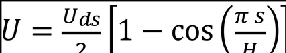

where –
s = distance penetrated into the gust (metre);
Uds = the design gust velocity in equivalent airspeed specified in sub-paragraph (a) (4) of this paragraph;
H = the gust gradient which is the distance (metre) parallel to the aeroplane’s flight path for the gust to reach its peak velocity.
(3) A sufficient number of gust gradient distances in the range 9 m (30 feet) to 107 m (350 feet) must be investigated to find the critical response for each load quantity.
(4) The design gust velocity must be:
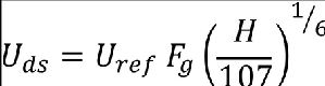
where –
Uref = the reference gust velocity in equivalent airspeed defined in sub-paragraph (a)(5) of this paragraph;
Fg = the flight profile alleviation factor defined in sub-paragraph (a)(6) of this paragraph.
(5) The following reference gust velocities apply:
(i) At aeroplane speeds between VB and VC: Positive and negative gusts with reference gust velocities of 17.07 m/s (56.0 ft/s) EAS must be considered at sea level. The reference gust velocity may be reduced linearly from 17.07 m/s (56.0 ft/s) EAS at sea level to 13.41 m/s (44.0 ft/s) EAS at 4572 m (15 000 ft). The reference gust velocity may be further reduced linearly from 13.41 m/s (44.0 ft/s) EAS at 4572 m (15 000 ft) to 6.36 m/s (20.86 ft/sec) EAS at 18288 m (60 000 ft).
(ii) At the aeroplane design speed VD: The reference gust velocity must be 0·5 times the value obtained under CS 25.341(a)(5)(i).
(6) The flight profile alleviation factor, Fg, must be increased linearly from the sea level value to a value of 1.0 at the maximum operating altitude defined in CS 25.1527. At sea level, the flight profile alleviation factor is determined by the following equation.
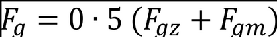
where –
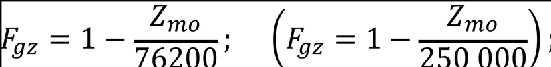
Zmo maximum operating altitude (metres (feet)) defined in CS 25.1527.
(7) When a stability augmentation system is included in the analysis, the effect of any significant system non-linearities should be accounted for when deriving limit loads from limit gust conditions.
(b) Continuous Turbulence Design Criteria. The dynamic response of the aeroplane to vertical and lateral continuous turbulence must be taken into account. The dynamic analysis must take into account unsteady aerodynamic characteristics and all significant structural degrees of freedom including rigid body motions. The limit loads must be determined for all critical altitudes, weights, and weight distributions as specified in CS 25.321(b), and all critical speeds within the ranges indicated in subparagraph (b)(3).
(1) Except as provided in subparagraphs (b)(4) and (b)(5) of this paragraph, the following equation must be used:
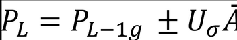
Where:
PL = limit load;
PL-1g = steady 1-g load for the condition;
A = ratio of root-mean-square incremental load for the condition to root-mean-square turbulence velocity; and
Uσ = limit turbulence intensity in true airspeed, specified in subparagraph (b)(3) of this paragraph.
(2) Values of Ā must be determined according to the following formula:
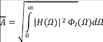
Where:
H(Ω) = the frequency response function, determined by dynamic analysis, that relates the loads in the aircraft structure to the atmospheric turbulence; and
ΦI(Ω) = normalised power spectral density of atmospheric turbulence given by:
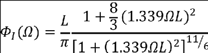
Where:
Ω = reduced frequency, rad/ft; and
L = scale of turbulence = 2,500 ft.
(3) The limit turbulence intensities, Uσ, in m/s (ft/s) true airspeed required for compliance with this paragraph are:
(i) At aeroplane speeds between VB and VC:
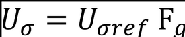
Where:
Uσref is the reference turbulence intensity that varies linearly with altitude from 27.43 m/s (90 ft/s) (TAS) at sea level to 24.08 m/s (79 ft/s) (TAS) at 7315 m (24000 ft) and is then constant at 24.08 m/s (79 ft/s) (TAS) up to the altitude of 18288 m (60000 ft); and
Fg is the flight profile alleviation factor defined in subparagraph (a)(6) of this paragraph;
(ii) At speed VD: Uσ is equal to 1/2 the values obtained under subparagraph (3)(i) of this paragraph.
(iii) At speeds between VC and VD: Uσ is equal to a value obtained by linear interpolation.
(iv) At all speeds both positive and negative incremental loads due to continuous turbulence must be considered.
(4) When an automatic system affecting the dynamic response of the aeroplane is included in the analysis, the effects of system non-linearities on loads at the limit load level must be taken into account in a realistic or conservative manner.
(5) If necessary for the assessment of loads on aeroplanes with significant non-linearities, it must be assumed that the turbulence field has a root-mean-square velocity equal to 40 percent of the Uσ values specified in subparagraph (3). The value of limit load is that load with the same probability of exceedance in the turbulence field as ĀUσ of the same load quantity in a linear approximated model.
(c) Supplementary gust conditions for wing mounted engines. For aeroplanes equipped with wing mounted engines, the engine mounts, pylons, and wing supporting structure must be designed for the maximum response at the nacelle centre of gravity derived from the following dynamic gust conditions applied to the aeroplane:
(1) A discrete gust determined in accordance with CS 25.341(a) at each angle normal to the flight path, and separately,
(2) A pair of discrete gusts, one vertical and one lateral. The length of each of these gusts must be independently tuned to the maximum response in accordance with CS 25.341(a). The penetration of the aeroplane in the combined gust field and the phasing of the vertical and lateral component gusts must be established to develop the maximum response to the gust pair. In the absence of a more rational analysis, the following formula must be used for each of the maximum engine loads in all six degrees of freedom:
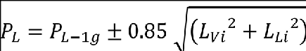
Where:
PL = limit load;
PL-1g = steady 1-g load for the condition;
LV = peak incremental response load due to a vertical gust according to CS 25.341(a); and
LL = peak incremental response load due to a lateral gust according to CS 25.341(a).
[Amdt 25/1]
[Amdt 25/12]