AMC No. 1 to CS 25.1329 Flight Guidance System
1 PURPOSE
This AMC
provides interpretative material and acceptable means of compliance with the
specifications of CS 25.1329 for Flight Guidance Systems. These means are intended to provide guidance
to supplement the engineering and operational
judgment that must form the basis of any compliance demonstration.
2 RELATED CERTIFICATION
SPECIFICATIONS
CSs
The
following are related CS standards:
|
CS 25.115 |
Take-off flight path |
|
CS 25.302 |
Interaction of systems and structures |
|
CS 25.671 |
Control systems, General |
|
CS 25.672 |
Stability augmentation and automatic and
power-operated systems |
|
CS 25.677 |
Trim systems |
|
CS 25.777 |
Cockpit controls |
|
CS 25.779 |
Motion and effect of cockpit controls |
|
CS 25.781 |
Cockpit control knob shape |
|
CS 25.901 |
Powerplant, General, Installation– |
|
CS 25.903 |
Powerplant, General, Engines |
|
CS 25.1301 |
Equipment, General, Function and installation– |
|
CS 25.1309 |
Equipment, systems, and installations |
|
CS 25.1322 |
Flight Crew Alerting System |
|
CS 25.1419 |
Ice protection |
|
CS 25.1420 |
Supercooled large drop icing condition |
|
CS 25.1581 |
Aeroplane Flight Manual, General |
|
CS-AWO |
All Weather Operations |
3 RELATED ADVISORY MATERIAL
EASA Acceptable
Means of Compliance (AMC) and FAA Advisory Circulars (FAA AC).
The
following guidance and advisory materials are related to this AMC:
|
AMC 20-115 |
Software Considerations for Airborne Systems and
Equipment Certification |
|
AMC 25.1309 |
System Design and Analysis |
|
AMC 25.1322 |
Alerting Systems |
|
AMC 25.1581 |
Aeroplane Flight Manual |
|
AMC 25-11 |
Electronic Display Systems |
|
FAA AC 20-129 |
Airworthiness Approval of Vertical Navigation
(VNAV) Systems for use in the U.S. National Airspace System (NAS) and Alaska |
|
FAA AC 25-7C |
Flight Test Guide for Certification of Transport
Category Airplanes |
|
FAA AC 25-12 |
Airworthiness Criteria for the Approval of Airborne
Windshear Warning Systems in Transport Category Airplanes |
|
FAA AC 120-28D |
Criteria for Approval of Category III Weather
Minima for Takeoff, Landing, and Rollout |
|
FAA AC 120-29A |
Criteria for Approval of Category I and Category II
Weather Minima for Approach |
|
FAA AC 120-41 |
Criteria for Operational Approval of Airborne Wind
Shear Alerting and Flight Guidance Systems |
4 RELATED
DOCUMENTS
JAA
documents:
|
JAR-OPS 1 |
Commercial Air Transportation (Aeroplanes) |
Industry
documents.
The
following are related Industry Standards that may be useful in the design
process:
|
SAE ARP5366 |
Autopilot, Flight Director and Autothrust Systems |
|
SAE ARP4754A/ EUROCAE ED-79A |
Guidelines for development of civil aircraft and
systems |
|
SAE ARP4100 |
Flight Deck and Handling Qualities Standards for
Transport Aircraft |
|
SAE ARP4761 |
Guidelines and Methods for Conducting the Safety
Assessment Process on Civil Airborne Systems and Equipment |
|
RTCA DO-160G/ |
Environmental Conditions and Test Procedures for
Airborne Equipment |
|
RTCA DO-254/ |
Design Assurance Guidance for Airborne Electronic
Hardware |
|
DOT/FAA/CT-96/1 |
Human Factors Design Guide for Acquisition of
Commercial-Off-the-Shelf Subsystems, Non-Developmental Items, and
Developmental Systems. |
5 DEFINITIONS AND ACRONYMS
The
following definitions apply to the specifications of CS 25.1329
and the guidance material provided in this AMC. They should not be assumed to
apply to the same or similar terms used in other regulations or AMC material.
Terms for which standard dictionary definitions apply are not defined in this
AMC.
|
Abnormal Condition |
See Non-normal |
|
Advisory |
EASA: Crew awareness is required and subsequent
crew action may be required. (AMC 25.1322) |
|
Alert |
A generic term used to describe a flight deck
indication meant to attract the attention of the flight crew to a non-normal
operational or aeroplane system condition without implying the degree or
level of urgency for recognition and corrective action by the crew.
Warnings, Cautions and Advisories are considered to be Alerts. EASA definition:
A signal to the crew intended to draw their attention |
|
Analysis |
The terms “analysis” and “assessment” are used
throughout. Each has a broad
definition and the two terms are to some extent interchangeable. However, the term analysis generally
implies a more specific, more detailed evaluation, while the term assessment
may be a more general or broader evaluation but may include one or more
types of analysis (AMC 25.1309). |
|
Arm |
A condition where the intent to transition to a new
mode or state has been established but the criteria necessary to make that
transition has not been satisfied. |
|
Assessment |
See the definition of analysis above (AMC 25.1309). |
|
Autopilot |
The autopilot function provides automatic control
of the aeroplane, typically in pitch, roll, and yaw. The term includes the sensors, computers,
power supplies, servo-motors/actuators and associated wiring, necessary for
its function. It includes any
indications and controllers necessary for the pilot to manage and supervise
the system. Any part of the autopilot
that remains connected to the primary flight controls when the autopilot is
not in use is regarded as a part of the primary flight controls. |
|
Autothrust |
The autothrust function provides automatic control
of the thrust of the aeroplane. The
term includes the sensors, computers, power supplies, servo-motors/actuators
and associated wiring, necessary for its function. It includes any indications and
controllers necessary for the pilot to manage and supervise the system. Any part of the autothrust that remains
connected to the engine controls when the autothrust is not in use is
regarded as a part of the engine control system. |
|
Caution |
A flight deck indication that alerts the flight
crew to a non-normal operational or aeroplane system condition that requires
immediate crew awareness. Subsequent pilot corrective compensatory action
will be required. |
|
Cognitive Task Analysis |
An analysis that focuses on the mental processes,
skills, strategies, and use of information required for task performance. |
|
Complex |
A system is Complex when its operation, failure
modes, or failure effects are difficult to comprehend without the aid of
analytical methods (AMC 25.1309). |
|
Conformal |
Positioned and scaled with respect to the outside
view |
|
Control Wheel Steering (CWS) |
A Flight Guidance System (FGS) function which, when
engaged, enables the pilot/first officer to manually fly the aeroplane by
positioning the flight control surfaces using the autopilot servos. The positions of the flight deck controls
(e.g., control column, control wheel) are determined by the FGS, which
converts them into autopilot servo commands.
The autopilot servos, in turn, drive the appropriate flight control
surfaces. |
|
Conventional |
A system is considered to be Conventional if its
functionality, the technological means used to implement its functionality,
and its intended usage are all the same as, or closely similar to, that of
previously approved systems that are commonly-used (AMC 25.1309). |
|
Engage |
A steady state that exists when a flight crew
request for mode or system functionality has been satisfied. |
|
Error |
An omission or incorrect action by a crewmember or
maintenance personnel, or a mistake in requirements, design, or
implementation (AMC 25.1309). |
|
Failure |
An occurrence that affects the operation of a
component, part, or element such that it can no longer function as intended
(this includes both loss of function and malfunction). NOTE: Errors
may cause failures, but are not considered to be failures (AMC 25.1309). |
|
Failure Condition |
A condition having an effect on the aeroplane
and/or its occupants, either direct or consequential, which is caused or
contributed to by one or more failures or errors, considering flight phase
and relevant adverse operational or environmental conditions, or external
events (AMC 25.1309) |
|
Fail Operational System |
A system capable of completing an operation,
following the failure of any single element or component of that system,
without pilot action. |
|
Fail Passive System |
A system which, in the event of a failure, results
in: (a) no
significant deviation in the aircraft flight path or attitude and (b) no
out-of-trim condition at disengagement that is not easily controlled by the
pilot. |
|
Flight Director |
A visual cue or set of cues that are used during
manual control of the aeroplane as command information to direct the pilot
how to manoeuvre the aeroplane, usually in pitch, roll and/or yaw, to track
a desired flight path. The flight
director, displayed on the pilot's primary head down attitude indicator
(ADI) or head up display (HUD), is a component of the flight guidance system
and is integrated with airborne attitude, air data and navigation systems. |
|
Flight Guidance System |
A system consisting of one or more of the following
elements: (a) autopilot,
(b) flight
director, (c) automatic
thrust control, and any interactions with stability augmentation
and trim systems. |
|
An aircraft area navigation system and associated
displays and I/O device(s) having complex multi-waypoint lateral (LNAV) and
vertical (VNAV) navigation capability (or equivalent), data entry
capability, data base memory to store route and instrument flight procedure
information, and display readout of navigation parameters. The Flight Management System provides
guidance commands to the FGS for the purpose of automatic navigation and
speed control when the FGS is engaged in an appropriate mode or modes (e.g.,
VNAV, LVAV, RNAV). |
|
|
Head-Up Display (HUD) |
A transparent optical display system located level
with and between the pilot and the forward windscreen. The HUD displays a combination of control,
performance, navigation, and command information superimposed on the
external field of view. It includes
the display element, sensors, computers and power supplies, indications and
controls. It is integrated with airborne attitude, air data and navigation
systems, and as a display of command information is considered a component
of the light guidance system. |
|
Inadvertent |
A condition or action that was not planned or intended. |
|
Latent Failure |
A failure is latent until it is made known to the
flight crew or maintenance personnel.
A significant latent failure is one, which would in combination with
one or more specific failures, or events result in a Hazardous or
Catastrophic Failure Condition (AMC 25.1309). |
|
Limit Flight Envelope |
This envelope is the most outside flight envelope,
generally associated with aeroplane design limits |
|
Mode |
A mode is system configuration that corresponds to
a single (or set of) FGS behaviour(s). |
|
Non-normal Condition |
A condition or configuration of the aeroplane that
would not normally be experienced during routine flight operations - usually
due to failures or non-routine operating conditions (e.g., excessive
out-of-trim due to fuel imbalance or under certain ferry conditions). |
|
Normal Condition |
Any fault free condition typically experienced in
normal flight operations. Operations typically well within the aircraft
flight envelope, and with routine atmospheric and environmental conditions. |
|
Normal Flight Envelope |
The range of altitude and operating speeds that are
defined by the aeroplane manufacturer as consistent with conducting flight
operations for which the aeroplane is designed. This envelope is generally
associated with practical, routine operation and/or prescribed conditions,
whether all-engine or engine inoperative. |
|
Override |
An action taken by the flight crew intended to
prevent, oppose or alter an operation being conducted by a flight guidance
function, without first disengaging that function. |
|
Rare Normal Condition |
A fault-free condition that is experienced
infrequently by the aeroplane due to significant environmental conditions
(e.g., significant wind, turbulence, or icing, etc.) |
|
Redundancy |
The presence of more than one independent means for
accomplishing a given function or flight operation (AC/AMC 25.1309). |
|
Select |
The flight crew action of requesting functionality
or an end state condition. |
|
Significant transient |
See “transient.” |
|
Stability Augmentation System |
Automatic systems, which provide or enhance
stability for specific aerodynamic characteristics of an aeroplane (e.g.,
Yaw Damper, Longitudinal Stability Augmentation System, Mach Trim). |
|
System |
A combination of components, parts, and elements
that are inter-connected to perform one or more specific functions (AMC
25.1309). |
|
Transient |
A disturbance in the control or flight path of the
aeroplane that is not consistent with response to flight crew inputs or
current environmental conditions. Minor transient: A transient that would not
significantly reduce safety margins, and which involves flight crew actions
that are well within their capabilities involving a slight increase in
flight crew workload or some physical discomfort to passengers or cabin
crew. Significant transient: A transient that would lead
to a significant reduction in safety margins, a significant increase in
flight crew workload, discomfort to the flight crew, or physical distress to
passengers or cabin crew, possibly including non-fatal injuries. NOTE: The flight crew should be able to respond to
any significant transient without: exceptional piloting skill, alertness, or strength,
forces greater than those given in CS 25.143(cd),
and accelerations or attitudes in the aeroplane that
might result in further hazard to secured or non-secured occupants. |
|
Warning |
A flight deck indication that alerts the flight
crew to a non-normal operational or aeroplane system requiring immediate
recognition. Immediate corrective or compensatory action by the flight crew
is required. |
|
AC |
Advisory Circular (FAA) |
|
ACAS |
Airborne Collision Avoidance System |
|
AMC |
Acceptable Means of Compliance |
|
AFM |
Aeroplane Flight Manual |
|
AGL |
Above Ground Level |
|
AIM |
Airman’s Information Manual |
|
ARP |
Accepted and Recommended Practice |
|
ATC |
Air Traffic Control |
|
AWO |
All Weather Operations |
|
CG |
Centre of Gravity |
|
CDI |
Course Deviation Indicator |
|
CWS |
Control Wheel Steering |
|
DA |
Decision Altitude |
|
DA(H) |
Decision Altitude (Height) |
|
DME |
Distance Measuring Equipment |
|
EFIS |
Electronic Flight Instrument System |
|
EVS |
Enhanced Vision System |
|
FAA |
Federal Aviation Administration |
|
FCOM |
Flight Crew Operations Manual |
|
F/D |
Flight Director |
|
FGS |
Flight Guidance System |
|
FLCH |
Flight Level Change |
|
FMA |
Flight Mode Annunciator |
|
FMS |
Flight Management System |
|
GA |
Go-around |
|
GLS |
GNSS Landing System |
|
GNSS |
Global Navigation Satellite System |
|
GPWS |
Ground Proximity Warning System |
|
HDD |
Head Down Display |
|
HUD |
Head-Up Display |
|
IAS |
Indicated Air Speed |
|
ICAO |
International Civil Aviation Organization |
|
ILS |
Instrument Landing System |
|
IMA |
Integrated Modular Avionics |
|
IMC |
Instrument Meteorological Conditions |
|
JAA |
Joint Aviation Authorities |
|
LNAV |
Lateral Navigation |
|
LOC |
Localizer |
|
MDA(H) |
Minimum Descent Altitude (Height) |
|
MLS |
Microwave Landing System |
|
MSL |
Mean Sea Level |
|
MSP |
Mode Select Panel |
|
MUH |
Minimum Use Height |
|
NAV |
Navigation |
|
ND |
Navigation Display |
|
NDB |
Non Directional Beacon |
|
NPA |
Notice of Proposed Amendment |
|
NPRM |
Notice of Proposed Rulemaking |
|
PF |
Pilot Flying |
|
PFD |
Primary Flight Display |
|
PNF |
Pilot Not Flying |
|
RNAV |
Area Navigation |
|
RNP |
Required Navigation Performance |
|
RTO |
Rejected Takeoff |
|
RVSM |
Reduced Vertical Separation Margin |
|
SAE |
Society of Automotive Engineering |
|
SVS |
Synthetic Vision System |
|
TCAS |
Traffic Collision Alert System |
|
TCS |
Touch Control Steering |
|
TO |
Takeoff |
|
TOGA |
Takeoff or Go-around |
|
VMC |
Visual Meteorological Conditions |
|
VNAV |
Vertical Navigation |
|
VOR |
VHF Omni Range |
|
WAT |
Weight Altitude Temperature |
This
advisory material replaces material previously provided in AMC 25.1329 for
Automatic Pilots. The automatic control and guidance systems in current
aircraft have evolved to a level that dictates a revision to current advisory
material.
There have
been dramatic changes in technology and system design, which have resulted in
much higher levels of integration, automation, and complexity. These changes
have also redefined the allocation of functions and interfaces between
systems. Relatively simple, dedicated systems have been replaced with digital
multi-function systems with more modes, and automatic changes in modes of
operation. The introduction of fly-by-wire flight control systems has created
new interface considerations for the FGS elements. These new systems are
capable of providing better performance, increased safety and decreased
workload. But if designed without consideration for the criteria in this AMC,
these systems could also be confusing and not immediately intuitive for the flight
crew. Significant operational experience has been gained on new generation
systems and guidance material is provided herein based on that experience.
This
advisory material is provided for Flight Guidance Systems, which include any
autopilot functions, flight director functions, automatic thrust control
functions and any interactions with stability augmentation and
trim functions.
7 GENERAL
The FGS is
primarily intended to assist the flight crew in the basic control and tactical
guidance of the aeroplane. The system may also provide workload relief to the
pilots and may provide a means to fly a flight path more accurately to support
specific operational requirements (e.g. RVSM, RNP, etc.).
The
applicant should establish, document and follow a design philosophy that
supports the intended operational use regarding the FGS behaviour; modes of
operation; pilot interface with controls, indications, and alerts; and mode
functionality.
Description
of the FGS behaviour and operation should be addressed from flight crew and
maintenance perspectives in appropriate documentation and training material.
Subsequent
sections of this advisory material provide interpretative material and
acceptable means of compliance with CS 25.1329 and the applicability of other
CS-25 rules to FGS (e.g., CS 25.1301, CS 25.1309).
The demonstrated means of compliance may include a combination of analysis,
laboratory testing, flight-testing, and simulator testing. The applicant
should coordinate with the authorities early in the certification programme,
via a certification plan, to reach agreement on the methods to be used to
demonstrate compliance.
7.1 Flight Guidance System
Functions
The
following functions, when considered separately and together, are considered
elements of a Flight Guidance System:
—
Flight
guidance and control (e.g., autopilot, flight director displayed head-down or
head-up);
—
Autothrottle/autothrust
systems;
—
Interactions
with stability augmentation and trim systems; and
—
Alerting,
status, mode annunciation, and situation information associated with flight
guidance and control functions.
The FGS includes those functions necessary to
provide guidance and control in conjunction with
an approach and landing system, such as:
—
the
Instrument Landing System (ILS),
—
the
Microwave Landing System (MLS) or
—
the
Global Navigation Satellite System (GNSS) Landing System (GLS).
The FGS also
includes those functions necessary to provide guidance and control in
conjunction with a Flight Management System (FMS). The FGS does not include
the flight planning and the generation of flight path and speed profiles tied
to waypoints and other flight planning aspects of the Flight Management System
(FMS). However, it does include the interface between the FMS and FGS
necessary for the execution of flight path and speed commands.
For the
purpose of this AMC the term “FGS” includes all the equipment necessary to
accomplish the FGS function, including the sensors, computers, power supplies,
servo-motors/actuators, and associated wiring. It includes any indications and
controllers necessary for the pilot to manage and supervise the system.
Any part of
the FGS that remains mechanically connected to the primary flight controls or
propulsion controls when the Flight Guidance System is not in use is regarded
as a part of the primary flight controls and propulsion system, and the
provisions for such systems are applicable.
7.3 Compliance with CS 25.1329
Table 7.3-A
lists the relevant paragraphs of CS 25.1329 and provides an indication where
acceptable means of compliance with each paragraph may be found within this
AMC.
TABLE 7.3-A.
Where Means of Compliance Can Be Found in this AMC
|
Section / Paragraph |
Rule Text |
Where Acceptable Means of Compliance Found in this
AMC |
|
CS 25.1329(a) |
Quick disengagement controls for the autopilot and
autothrust functions must be provided for each pilot. The autopilot quick
disengagement controls must be located on both control wheels (or
equivalent). The autothrust quick disengagement controls must be located on
the thrust control levers. Quick disengagement controls must be readily
accessible to each pilot while operating the control
wheel (or equivalent) and thrust control levers. |
Section 8.1, Autopilot Engagement/Disengagement and Indications Section 8.3, Autothrust Engagement/Disengagement
and Indications |
|
CS 25.1329(b) |
The effects of a failure of the system to disengage
the autopilot or autothrust functions when manually commanded by the pilot
must be assessed in accordance with the specifications of CS 25.1309. |
Section 8.1, Autopilot Engagement/Disengagement and
Indications Section 8.3, Autothrust Engagement/Disengagement
and Indications Section
13.6, Safety Assessment – Failure to Disengage the FGS |
|
CS 25.1329(c) |
Engagement or switching of the flight guidance
system, a mode, or a sensor must not produce a transient response affecting
the control or flight path of the aeroplane any greater than a minor
transient. |
Section 8, FGS Engagement, Disengagement, and
Override |
|
CS 25.1329(d) |
Under normal conditions, the disengagement of any
automatic control functions of a flight guidance system must not produce a
transient response affecting the control or flight path of the aeroplane any
greater than a minor transient. |
Section 8, FGS Engagement, Disengagement, and
Override Section 13, Safety
Assessment |
|
CS 25.1329(e) |
Under rare-normal or non-normal conditions the
disengagement of any automatic control functions of a flight guidance system
must not produce a transient response affecting the control or flight path
of the aeroplane any greater than a significant transient. |
Section 8, FGS Engagement, Disengagement, and
Override Section 9.3.3, Awareness of Potential Significant
Transient Condition (“Bark before Bite”) |
|
CS 25.1329 (f) |
The function and direction of motion of each
command reference control (e.g., heading select, vertical speed) must be
readily apparent or plainly indicated on, or adjacent to, each control if
necessary to prevent inappropriate use or confusion. |
Section 9, Controls, Indications and Alerts |
|
CS 25.1329(g) |
Under any condition of flight appropriate to its
use, the Flight Guidance System must not: —
produce unacceptable loads
on the aeroplane (in accordance with CS 25.302), or —
create hazardous
deviations in the flight path. This applies to both fault-free operation and in
the event of a malfunction, and assumes that the pilot begins corrective
action within a reasonable period of time. |
Section 10, Performance of
Function Section 13, Safety Assessment Section 14, Compliance Demonstration using Flight
Test and Simulation |
|
CS 25.1329(h) |
When the flight guidance system is in use, a means
must be provided to avoid excursions beyond an acceptable margin from the
speed range of the normal flight envelope.
If the aircraft experiences an excursion outside this range, the
flight guidance system must not provide guidance or control to an unsafe
speed. |
Section 10.4, Speed Protection |
|
CS 25.1329(i) |
The FGS functions, controls, indications, and
alerts must be designed to minimize flight crew errors and confusion
concerning the behaviour and operation of the FGS. Means must be provided to
indicate the current mode of operation, including any armed modes,
transitions, and reversions. Selector
switch position is not an acceptable means of indication. The controls and indications must be
grouped and presented in a logical and consistent manner. The indications must be visible to each
pilot under all expected lighting conditions. |
Section 9, Controls Indications and Alerts |
|
CS 25.1329(j) |
Following disengagement of the autopilot, a warning
(visual and aural) must be provided to each pilot and be timely and distinct
from all other cockpit warnings. |
Section 8.1.2.1, Autopilot Disengagement Alerts Section 13, Safety Assessment |
|
Following disengagement of the autothrust function,
a caution must be provided to each pilot. |
Section 8.3.2, Autothrust Disengagement Section 13, Safety Assessment |
|
|
CS 25.1329(l) |
The autopilot must not create an unsafe condition
when the flight crew applies an override force to the flight controls. |
Section 8.4.1, Flight Crew Override of the FGS –
Autopilot Section
13, Safety Assessment |
|
CS 25.1329(m) |
During autothrust operation, it must be possible
for the flight crew to move the thrust levers without requiring excessive
force. The autothrust response to flight crew override must not create an
unsafe condition. |
Section 8.4.2, Flight Crew Override of the FGS -
Autothrust Section 13, Safety Assessment |
8 Flight Guidance System Engagement,
Disengagement and Override
The
characteristics of the FGS during engagement, disengagement and override have
caused some concern with systems on some aeroplanes. The following criteria
should be addressed in the design of a FGS.
8.1 Autopilot
Engagement/Disengagement and Indications
Autopilot
engagement and disengagement should be accomplished in a manner consistent
with other flight crew procedures and tasks, and should not require undue
attention.
8.1.1 Autopilot Engagement
Each pilot
should be able to select the autopilot function of the flight guidance system
with a single switch action. The single switch action should engage pitch and
roll axes. The autopilot system should provide positive indication to the
flight crew that the system has been engaged.
The selector switch position is not acceptable as a means of indication
(reference CS 25.1329(i)).
NOTE: If
an operational need is identified for split-axis engagement, then annunciation
or indication should be provided for each axis.
For
aeroplanes with more than one autopilot installed, each autopilot may be
individually selected and should be so annunciated. It should not be possible
for multiple autopilots to be engaged in different modes.
The
engagement of the autopilot should be free of perceptible transients. Under
dynamic conditions, including manoeuvring flight, minor transients are
acceptable.
Without a
flight director engaged, the initial lateral and vertical modes should be
consistent with minimal disturbance from the flight path. For example, the
lateral mode at engagement may roll the aeroplane to wings level and then hold
the aeroplane heading/track or maintain the existing bank angle (if in a
normal range). A heading/track pre-select at engagement function may be
provided if precautions are taken to ensure that selection reflects the
current intent of the flight crew. The modes at engagement should be
annunciated and any associated selected target values should be displayed.
With a
flight director engaged, the autopilot should engage into a mode consistent
(i.e., the same as, or if that is not possible, then compatible with) the
active flight director mode of operation. Consideration should be given to the
mode into which the autopilot will engage when large commands are present on
either or both flight directors. For example, consideration should be given
whether to retain the active flight director mode or engage the autopilot into
the basic mode, and the implications for current flight path references and
targets. The potential for flight crew confusion and unintended changes in
flight path or modes should be considered.
Regardless
of the method used, the engagement status (and changes in status) of the
autopilot(s) should be clearly indicated and should not require undue
attention or recall.
For modes
that use multiple autopilots, the additional autopilots may engage
automatically at selection of the mode or after arming the mode. A means
should be provided to determine that adequate autopilot capability exists to
support the intended operation (e.g., "Land 2" and "Land
3" are used in some aircraft).
NOTE: The design should consider the possibility
that the pilot may attempt to engage the autopilot outside of the normal
flight envelope. It is not required that the autopilot should compensate for
unusual attitudes or other situations outside the normal flight envelope,
unless that is part of the autopilot’s intended function.
In
consequence of specifications in CS 25.1329(d), under normal conditions,
automatic or manual disengagement of the autopilot must be free of significant
transients or out-of-trim forces that are not consistent with the manoeuvres
being conducted by the aeroplane at the time of disengagement. If multiple
autopilots are engaged, any disengagement of an individual autopilot must be
free of significant transients and should not adversely affect the operation
of the remaining engaged autopilot(s) CS 25.1329(d)).
Under
non-normal or rare-normal conditions (see CS 25.1329(e)),
disengagement of the autopilot may result in a significant transient. The
flight crew should be able to respond to a significant transient without:
—
exceptional
piloting skill, alertness, or strength,
—
forces
greater than those given in CS 25.143(d), and
—
accelerations
or attitudes in the aeroplane that might result in a hazard to secured or
non-secured occupants.
The flight
crew should be made aware (via a suitable alerting or other indication) of
conditions or situations (e.g., continued out-of-trim) that could result in a
significant transient at disengagement. (See Section 9.3.3 on Awareness of
Potential Significant Transient Condition (“Bark before Bite”)).
8.1.2.1 Autopilot Disengagement Alerts (see CS 25.1329(j))
Since it is
necessary for a pilot to immediately assume manual control following
disengagement of the autopilot (whether manual or automatic), a visual and
aural warning must be given (CS 25.1329(j)).
Visual
warning: a timely visual warning, distinct from all other cockpit warnings,
must be provided and must be located in the primary field of view for both
pilots. See CS 25.1329(j).
Aural
warning: a timely aural warning must be provided and must be distinct from all
other cockpit warnings. See CS 25.1329(j). Even when the autopilot is
disengaged by a pilot, it should sound for long enough to ensure that it is
heard and recognised by the pilot and other flight crew members (at least a
single cycle), but not for so long that it adversely affects communication
between crew members or that it is a distraction. The aural warning should
continue until silenced by one of the following means:
—
Activation
of an autopilot quick disengagement control;
—
Re-engagement
of the autopilot; or
—
Another
acceptable means.
Multiple-autopilot
system: Disengagement of an autopilot within a multiple‑autopilot system
(e.g., downgraded capability), requiring immediate flight crew awareness and
possible timely action, should cause a Caution level alert to be issued to the
flight crew.
Disengagement
of an autopilot within a multiple-autopilot system, requiring only flight crew
awareness, should cause a suitable advisory to be issued to the flight crew.
Disengagement
of an autopilot within a multiple-autopilot system (e.g., downgraded
capability), requiring immediate flight crew awareness and possible timely
action, should cause a Caution level alert to be issued to the flight crew.
Disengagement
of an autopilot within a multiple-autopilot system, requiring only flight crew
awareness, should cause a suitable advisory to be issued to the flight crew.
8.1.2.2 Quick Disengagement Control (see CS 25.1329(a))
The purpose
of the “Quick Disengagement Control” is to ensure the capability for each
pilot to manually disengage the autopilot quickly with a minimum of pilot
hand/limb movement. The “Quick Disengagement Control” must be located on each
control wheel or equivalent CS 25.1329(a) and should be within easy
reach of one or more fingers/thumb of the pilot’s hand when the hand is in a
position for normal use on the control wheel or equivalent. The “Quick
Disengagement Control” should meet the following criteria:
(a) Be accessible and operable from a normal
hands-on position without requiring a shift in hand position or grip on the
control wheel or equivalent;
(b) Be operable with one hand on the control
wheel or equivalent and the other hand on the thrust levers;
NOTE: When establishing location of the quick
disengagement control, consideration should be given to:
—
its
accessibility with large displacements of, or forces on, the control wheel (or
equivalent), and
—
the
possible need to operate the quick disengagement control with the other hand.
(c) Be easily located by the pilot without
having to first locate the control visually;
(d) Be designed so that any action to operate
the “Quick Disengagement Control” should not cause an unintended input to the
control wheel or equivalent; and
(e) Be designed to minimize inadvertent
operation and interference with other nearby control wheel (or equivalent)
switches/devices (e.g., radio control, trim).
8.1.2.3 Alternative Means of Autopilot Disengagement
When a CS 25.1309
assessment shows a need for an alternative means of disengagement, the
following should be addressed:
—
Independence,
—
The
alternate means should be readily accessible to each pilot,
—
Latent
failure/reliability of the alternate means.
The
following means of providing an alternative disengagement have been found to
be acceptable:
—
Selection
of the engagement control to the “off” position.
—
Disengage
bar on mode selector panel.
—
Trim
switch on yoke.
NOTE: Use
of circuit breakers as a means of disengagement is not considered to be
acceptable.
8.1.2.5 Flight Crew Pitch Trim Input
If the
autopilot is engaged and the pilot applies manual pitch trim input, either the
autopilot should disengage with no more than a minor transient, or pitch trim
changes should be inhibited (see CS 25.1329(l)).
8.2 Flight Director
Engagement/Disengagement and Indications
Engagement
and disengagement should be accomplished consistent with other flight crew
procedures and tasks and should not require undue attention.
8.2.1 Flight Director Engagement
A means should
be provided for each pilot to select (i.e., turn on) and deselect the flight
director for display on their primary flight display (e.g., attitude display).
The selection status of the flight director and the source of flight director
guidance should be clear and unambiguous. Failure of a selected flight
director should be clearly annunciated.
A flight
director is considered “engaged” if it is selected and displaying guidance
cues.
NOTE: The
distinction is made between “engaged” and “selected” because the flight
director might be selected, but not displaying guidance cue(s) (e.g., the
cue(s) are biased out of view).
If there are
multiple flight directors, and if required for crew awareness, indications
should be provided to denote which flight director is engaged (e.g., FD1, FD2,
HUD source). For aeroplanes with multiple flight directors installed, both
flight directors should always be in the same armed and active FGS modes. The
selection status of each flight director should be clear and unambiguous for
each pilot. In addition, indications should be provided to denote loss of
flight director independence (i.e., first officer selection of captain’s
flight director).
A flight
director should engage into the current modes and targets of an already
engaged autopilot or flight director, if any. With no autopilot engaged, the
basic modes at engagement of the flight director functions should be
established consistent with typical flight operations.
NOTE: The
engagement of the pitch axis in Vertical Speed or Flight Path Angle, and
engagement of the lateral axis in Heading Hold, Heading Select or Bank Angle
Hold have been found to be acceptable.
Since the
HUD can display flight guidance, the HUD guidance mode should be indicated to
both pilots and should be compatible with the active head-down flight director
mode.
Engagement
during manoeuvring flight should be considered.
NOTE: The
design should consider the safety consequences if it is possible for the
flight director to engage outside of the normal flight envelope. It is not
required that the flight director should compensate for unusual attitudes or
other situations outside the normal flight envelope, unless that is part of
the flight director’s intended function.
The flight
director command guidance cue(s) will typically be displayed when the flight
director is selected and valid command guidance is available or if it is
automatically providing guidance as per paragraph 8.2.1.2 below. The flight
director guidance cue(s) should be removed when guidance is determined to be
invalid. The display of guidance cue(s) (e.g., flight director bars) is
sufficient indication that the flight director is engaged.
8.2.1.2 Reactive Windshear Flight Director Engagement
For
aeroplanes equipped with a flight director windshear guidance system, flight
director engagement should be provided, consistent with the criteria contained
in FAA AC’s 25-12 and 120-41.
8.2.2 Flight Director
Disengagement
There may be
a means for each pilot to readily deselect his or her on-side flight director
function. Flight crew awareness of disengagement and de-selection is
important. Removal of guidance cue(s) alone is not sufficient indication of
de-selection, because the guidance cue(s) may be removed from view for a
number of reasons, including invalid guidance, autopilot engagement, etc.
Therefore, the flight director function should provide clear and unambiguous
indication (e.g., switch position or status) to the flight crew that the
function has been deselected.
8.3 Autothrust
Engagement/Disengagement and Indications
The autothrust function should be designed with
engagement and disengagement characteristics that provide the flight crew
positive indication that the system has been engaged or disengaged. Engagement
and disengagement should be accomplished in a manner consistent with other
flight crew procedures and tasks and should not require undue attention.
The
autothrust engagement controls should be accessible to each pilot. The
autothrust function must provide the flight crew positive indication that the
system has been engaged.
The
autothrust function should be designed to prevent inadvertent engagement and
inadvertent application of thrust, for both on-ground and in-air operations
(e.g., provide separate arm and engage functions).
The
autothrust normally should be designed to preclude inadvertent engagement.
However, intended modes such as a “wake up” mode to protect for unsafe speeds
may be acceptable (see Section 10.4.1 on Low Speed Protection). If such
automatic engagement occurs, it should be clear to the flight crew that
automatic engagement has occurred, the automatic engagement should not cause
any unsafe condition (e.g., unsafe pitch attitudes or unsafe pitching
moments), to show compliance with CS 25.1329(c), and the reason for automatic
engagement should be clear and obvious to the flight crew.
NOTE: The
design should consider the possibility that the pilot may attempt to engage
the autothrust function outside of the normal flight envelope or at excessive
(or too low) engine thrust. It is not expected that the autothrust feature
should compensate for situations outside the normal flight envelope or normal
engine operation range, unless that is part of the intended function of the
autothrust system.
8.3.2 Autothrust Disengagement
Autothrust
disengagement should not cause any unsafe condition (e.g., pitch attitude,
pitching moment, or significant thrust transient), to show compliance with CS 25.1329(d),
and the disengagement should not preclude, inhibit, or interfere with timely
thrust changes for go-around, landing, or other manoeuvres requiring manual
thrust changes.
The
autothrust normally should be designed to preclude inadvertent disengagement
during activation of autothrust modes of operation.
Following
disengagement of the autothrust function, positive indication of disengagement
should include at least a visual flight crew alert and deletion of autothrust
‘engaged’ status annunciations (to show compliance with CS 25.1329(k)).
For automatic disengagement, visual indications should persist until cancelled
by flight crew action. For manual disengagement, if an aural is provided,
visual indications should persist for some minimum period. If an aural is not
provided, the visual indications should persist until cancelled by flight crew
action. For aural indication, if provided, an aural alert of sufficient
duration and volume should be provided to assure that the flight crew has been
alerted that disengagement has occurred. An extended cycle of an aural alert
is not acceptable following disengagement if such an alert can significantly
interfere with flight crew coordination or radio communication. Disengagement
of the autothrust function is considered a Caution alert.
8.3.2.1 Autothrust Quick Disengagement Control
Autothrust
quick disengagement controls must be provided for each pilot on the respective
thrust control lever as stated in CS 25.1329(a). A single-action, quick
disengagement switch should be incorporated on the thrust control so that
switch activation can be executed when the pilot’s other hand is on the flight
controls. The disengagement control should be positioned such that inadvertent
disengagement of the autothrust function is unlikely. Positioning the control
on the outboard side has been shown to be acceptable for multiengine aircraft.
Thrust lever knob-end-mounted disengagement controls available on both sides
to facilitate use by either pilot have been shown to be preferable to those
positioned to be accessible by the pilot’s palm.
8.4 Flight Crew Override of
the FGS
The following sections discuss criteria
related to the situation where the flight crew overrides the FGS.
1) The autopilot should disengage when the
flight crew applies a significant override force to the controls. The
applicant should interpret “significant” as a force that is consistent with an
intention to overpower the autopilot by either or both pilots. The autopilot
should not disengage for minor application of force to the controls (e.g., a
pilot gently bumping the control column while entering or exiting a pilot seat
during cruise).
NOTE: 111
N (25 lbf) at the control column or wheel has been determined to be a
significant override force level for other than approach operations on some
aircraft types. To reduce nuisance disengagement, higher forces have been
found acceptable for certain approach, landing, and go-around operations on
some aircraft types. The force to
disengage an autopilot is not necessarily the force required at the column to
oppose autopilot control (e.g., cause elevator movement). The corresponding
forces for a side stick or centre stick controller may be different.
Under normal
conditions, a significant transient should not result from autopilot
disengagement when the flight crew applies an override force to the controls
(to show compliance with CS 25.1329(d).
Sustained or
incremental application of force below the disengagement threshold should not
result in a hazardous condition (e.g., the automatic trim running that results
in unacceptable aeroplane motion if the autopilot were to automatically
disengage, or when manually disengaged).
2) If the autopilot is not designed to
disengage in response to any override force, then the response shall be shown
to be safe (CS 25.1329(l)).
a) The sustained application of an override
force should not result in a potential hazard when the flight crew manually
disengages the autopilot or abruptly releases the force on the controls.
During sustained application of an override force, the automatic trim should
not run to oppose the flight crew commands in any manner that would result in
unacceptable aeroplane motion. Mitigation may be accomplished through the
provision of an appropriate alert and flight crew procedure.
NOTE: The term ‘sustained application
of override force’ is intended to describe a force that is applied to the
controls, which may be small, slow, and sustained for some period of time.
This may be due to an inadvertent crew action or may be an intentional crew
action meant to ‘assist’ the autopilot in a particular manoeuvre. (See Chapter
14, Compliance Demonstration Using Flight Test and Simulation, paragraph
14.1.5, Flight Crew Override of the Flight Guidance System, of this AMC for
more information.)
b) Transients resulting from an override
force: Under normal conditions, a significant transient should not result from
manual autopilot disengagement after the flight crew has applied an override
force to the controls (CS 25.1239(d)).
NOTE 1:
the term ‘override force’ is intended to describe a pilot action that is
intended to prevent, oppose or alter an operation being conducted by a flight
guidance function, without first disengaging that function. One possible
reason for this action could be an avoidance manoeuvre (such as responding to
an ACAS/TCAS Resolution Advisory) that requires immediate action by the flight
crew and would typically involve a rapid and forceful input from the flight
crew.
NOTE 2: For control wheel steering considerations, refer to Section 11.6.
It should be
possible for the pilot to readily override the autothrust function and set
thrust by moving the thrust levers (or equivalent) with one hand. CS 25.1329(m)
requires that the autothrust response to a flight crew override must not
create an unsafe condition.
Autothrust
functions may be designed to safely remain engaged during pilot override.
Alternatively, autothrust functions may disengage as a result of pilot
override, provided that the design prevents unintentional autothrust
disengagement and adequately alerts the flight crew to ensure pilot awareness.
8.5 FGS Engagement Mode
Compatibility
The
philosophy used for the mode at engagement of the autopilot, flight director,
and autothrust functions should be provided in flight crew training material.
It should
not be possible to select incompatible FGS command or guidance functions at
the same time (e.g., commanding speed through elevator and autothrust at the
same time).
9 Controls,
Indications and Alerts
The
human-machine interface with the FGS is a key to ensuring safe, effective and
consistent FGS operation. The manner in which FGS information is depicted to
flight crews is essential to the flight crew awareness, and therefore, the
safe operation of the FGS.
The
controls, indications, and alerts must be so designed as to minimize flight
crew errors and confusion (CS 25.1329(i)). Indications and alerts should be
presented in a manner compatible with the procedures and assigned tasks of the
flight crew and provide the necessary information to perform those tasks. The
indications must be grouped and presented in a logical and consistent manner
and be visible from each pilot’s station under all expected lighting
conditions (CS 25.1329(i)). The choice of colours, fonts, font size,
location, orientation, movement, graphical layout and other characteristics
such as steady or flashing should all contribute to the effectiveness of the
system. Controls, indications, and alerts should be implemented in a
consistent manner.
It is
recommended that the applicant evaluate the adequacy and effectiveness of the
information provided by the FGS interface (i.e., controls, indications,
alerts, and displays) to ensure flight crew awareness of FGS behaviour and
operation. See Section 14, Compliance
Demonstration using Flight Test and Simulation, for more discussion of
appropriate analyses (which may include, for example, cognitive task analysis
as a basis for evaluation).
The FGS
controls should be designed and located to provide convenient operation to
each crewmember and they must be designed to minimize crew errors, confusion
and inadvertent operation (CS 25.1329(i)). To achieve this, CS 25,1329(f) requires that command reference controls to select target values
(e.g., heading select, vertical speed) should operate as specified in CS 25.777(b)
and 25.779(a) for cockpit controls. The function and
direction of motion of each control must be readily apparent or plainly
indicated on, or adjacent to, each control if needed to prevent inappropriate
use or confusion (CS 25,1329(f)). CS 25.781 also provides requirements for the
shapes of the knobs. The design of the FGS should address the following
specific considerations:
—
Differentiation
of knob shape and position. (Errors have included confusing speed and heading
knobs on the mode selector panel.)
—
Design
to support correct selection of target values. (Use of a single control (e.g.,
concentric controls) for selecting multiple command reference targets has
resulted in erroneous target value selection.)
—
Commonality
of control design across different aircraft to prevent negative transfer of
learning with respect to operation of the controls. (Activation of the wrong
thrust function has occurred due to variation of TOGA and autothrust
disengagement function between aeroplane types- negative transfer of learning
with respect to operation of the controls.)
—
Positioning
of individual FGS controls, FMAs, and related primary flight display
information so that, as far as reasonably practical, items of related function
have similarly related positions. (Misinterpretation and confusion have
occurred due to the inconsistent arrangement of FGS controls with the
annunciations on the FMA.)
—
Design
to discourage or avoid inadvertent operation; e.g., engagement or
disengagement (to show compliance with CS 25.777(a)).
9.2 Flight
Guidance Mode Selection, Annunciation, and Indication
Engagement
of the Flight Guidance System functions must be suitably annunciated to each
pilot (to show compliance with CS 25.1329(i)), as described in Section 8,
Flight Guidance System Engagement, Disengagement, and Override. The FGS mode
annunciations must effectively and unambiguously indicate the active and armed
modes of operation (CS 25.1329(i)). The mode annunciation should
convey explicitly, as simply as possible, what the FGS is doing (for active
modes), what it will be doing (for armed modes), and target information (such
as selected speed, heading, and altitude) for satisfactory flight crew
awareness.
Mode
annunciation must indicate the state of the system and not just switch
position or selection (CS 25.1329(i)). Mode annunciation should be
presented in a manner compatible with flight crew procedures / tasks and
consistent with the mode annunciation design for the specific aircraft type
(i.e., compatible with other flight deck systems mode annunciations).
Operationally
relevant mode changes and, in particular, mode reversions and sustained speed
protection, should be clearly and positively annunciated to ensure flight crew
awareness. Altitude capture is an example of an operationally relevant mode
that should be annunciated because pilot actions may have different effects on
the aeroplane. Annunciation of sustained speed protection should be clear and
distinct to ensure flight crew awareness. It should be made clear to the pilot
if a mode has failed to arm or engage (especially due to invalid sensor data).
FGS sub-modes (e.g., sub-modes as the FGS transitions from localizer capture
to localizer track) that are not operationally relevant need not be
annunciated.
In-service
experience has shown that mode annunciation alone may be insufficient (unclear
or not compelling enough) to communicate mode changes to the flight crew,
especially in high workload situations. Therefore, the safety consequences of
the flight crew not recognizing mode changes should be considered. If
necessary, an appropriate alert should be used.
Mode
annunciations should be located in the forward field of view (e.g., on the
primary flight display). Mode selector switch position or status is not
acceptable as the sole means of mode annunciation (CS 25.1329(i)).
Modes and mode changes should be depicted in a manner that achieves flight
crew attention and awareness. Aural notification of mode changes should be
limited to special considerations. Colours, font type, font size, location,
highlighting, and symbol flashing have historical precedent as good
discriminators, when implemented appropriately. The fonts and font size should
be chosen so that annunciation of FGS mode and status information is readable
and understandable, without eye strain, when viewed by the pilot seated at the
design eye position.
Colour
should be used in a consistent manner and assure compatibility with the
overall use of colour on the flight deck. Specific colours should be used such
that the FGS displays are consistent with other flight deck systems, such as a
Flight Management System. The use of monochrome displays is not precluded,
provided that the aspects of flight crew attention and awareness are
satisfied. The use of graphical or symbolic (i.e., non-textual) indications is
not precluded. Implementation of such discriminators should follow accepted
guidelines as described in applicable international standards (e.g., AMC
25-11) and should be evaluated for their consistency with and integration with
the flight deck design. Engaged modes should be annunciated at different locations
and with different colours than armed modes to assist in mode recognition. The
transition from an armed mode to an engaged mode should provide an additional
attention-getting feature, such as boxing and flashing on an electronic
display (per AMC 25-11) for a suitable, but brief, period (e.g., ten seconds),
to assist in flight crew awareness.
The failure
of a mode to engage/arm when selected by the pilot should be apparent. Mode
information provided to the pilot should be sufficiently detailed, so that the
consequences of the interaction (e.g., ensuing mode or system configuration
that has operational relevance) can be unambiguously determined. The FGS
interface should provide timely and positive indication when the flight
guidance system deviates from the pilot's direct commands (e.g., a target
altitude, or speed setting) or from the pilot's pre-programmed set of commands
(e.g., waypoint crossing). The interface should also provide clear indication
when there is a difference between pilot-initiated commands (e.g., pilot
engages positive vertical speed and then selects an altitude that is lower
than the aircraft altitude). The default action taken by the FGS should be
made apparent.
The operator
should be provided with appropriate description of the FGS modes and their
behaviour.
9.3 Flight Guidance Alerting
(Warning, Caution, Advisory, and Status)
Alerting
information should follow the provisions of CS 25.1322
and associated advisory material. Alerts for FGS engagement and disengagement
are described in Section 8, Flight Guidance System Engagement, Disengagement,
and Override.
There should
be some method for the flight crew to determine and monitor the availability
or capability of the Flight Guidance System (e.g., for dispatch), where the
intended operation is predicated on the use of the FGS. The method of
monitoring provided should take account of the hazard resulting from the loss
of the autopilot function for the intended operation.
9.3.1 Alerting for Speed
Protection
To assure
crew awareness, an alert should be provided when a sustained speed protection
condition is detected. This is in addition to any annunciations associated
with mode reversions that occur as a consequence of invoking speed protection
(see Section 10.4, Speed Protection). Low speed protection alerting should
include both an aural and a visual component. High-speed protection alerts
need only include a visual alert component because of existing high-speed
aural alert requirements, but does not preclude giving an earlier alert.
Alerting for
speed protection should be consistent with the protection provided and with
the other alerts in the flight deck. Care should be taken to set appropriate
values for indicating speed protection that would not be considered a nuisance
for the flight crew.
9.3.2 Loss of Autopilot Approach
Mode
The loss of
the approach mode requires immediate flight crew awareness. This may be
accomplished through autopilot disengagement and related warning (as required
by CS 25.1329(j) and specified in 8.1.2.1 of this AMC). If the
autopilot remains engaged and reverts to a non-approach mode, an appropriate
aural warning and/or visual alert should be provided.
9.3.3 Awareness of Potential
Significant Transient Condition (“Bark before Bite”)
There have
been situations where an autopilot is engaged, operating normally, and
controlling up to the limit of its authority for an extended period of time,
and the flight crew was unaware of the situation. This service experience has
shown that, without timely flight crew awareness and action, this situation
can progress to a loss of control after autopilot disengagement, particularly
in rare normal or non-normal conditions. However, with adequate flight crew
awareness and pilot action, loss of control may be prevented.
To help
ensure crew awareness and timely action, appropriate alert(s) (generally
caution or warning) should be provided to the flight crew for conditions that
could require exceptional piloting skill or alertness for manual control
following autopilot disengagement (e.g., significantly out of trim). The
number and type of alerts required would be determined by the unique
situations that are being detected and by the crew procedures required to
address those situations. Any alert should be clear and unambiguous, and be
consistent and compatible with other flight deck alerts. Care should be taken
to set appropriate thresholds for these alerts such that they are not
considered a nuisance for the flight crew.
Situations
that should be considered for an alert include:
Sustained
Lateral Control Command: If the autopilot is holding a sustained lateral
control command, it could be indicative of an unusual operating condition
(e.g., asymmetric lift due to icing, fuel imbalance, asymmetric thrust) for
which the autopilot is compensating. In the worst case, the autopilot may be
operating at or near its full authority in one direction. If the autopilot
were to disengage while holding this lateral trim, the result would be that
the aeroplane would undergo a rolling moment that could possibly take the
pilot by surprise. Therefore, a timely alert should be considered to permit
the crew to manually disengage the autopilot and take control prior to any
automatic disengagement which might result from the condition.
Sustained
Longitudinal Out of Trim: If the autopilot is holding sustained longitudinal
trim, it could be indicative of an unusual operating condition (e.g., an
inoperative horizontal stabilizer) for which the autopilot is compensating. If
the autopilot were to disengage while holding this longitudinal trim, the
result would be that the aeroplane would undergo an abrupt change in pitch
that could possibly take the pilot by surprise. Therefore, a timely alert
should be considered to permit the crew to manually disengage the autopilot
and take control prior to any automatic disengagement, which might result from
the condition.
Bank and
Pitch Angles Beyond Those Intended for Autopilot Operations: Most autopilots
are designed with operational limits in both the pitch and roll axes, such
that those predetermined limits will not be purposely exceeded. If the
aeroplane exceeds those limits, it could be indicative of a situation (which
may not be covered by items 1. or 2.) that requires the pilot to intervene.
Therefore, a timely alert should be considered to bring this condition to the
attention of the flight crew to and permit the crew to manually disengage the
autopilot and take control prior to any automatic disengagement, which might
result.
It is
preferable that the autopilot remains engaged during out-of-trim conditions.
However, if there is an automatic disengagement feature due to excessive
out-of-trim, an alert should be generated and should precede any automatic
disengagement with sufficient margin to permit timely flight crew recognition
and manual disengagement. See also Section 8.4, Flight Crew Override of the
FGS, for related material.
NOTE: This
section is not intended to require alerting for all instances of automatic
autopilot disengagement. It is intended only for conditions, which, if not
addressed, would lead to such disengagement, which, could result in a
significant transient for which the pilot may be unprepared. The intent is to
provide crew awareness that would allow the flight crew to be prepared with
hands on controls and take appropriate corrective action before the condition
results in a potentially hazardous aeroplane configuration or state.
NOTE: This
section describes alerting requirements for conditions resulting in unintended
out-of-trim operation. There are FGS functions that can intentionally produce
out-of-trim operation (e.g. parallel rudder operation in align or engine
failure compensation modes, pitch trim operation during the approach/landing
to provide trim up/flare spring bias, or pitch trim operation for certain
types of Speed/Mach trim systems). It is not the intent of this section to
require alerts for functions producing intentional out-of-trim conditions.
Other system indications (e.g., mode and status annunciations) should be
provided to make the crew aware of the operation of these functions where
appropriate.
9.3.4 Failures Affecting Flight
Director Guidance
Wherever
practicable a failure should cause the immediate removal from view of the
guidance information. If the guidance information is retained but a warning
given instead, it should be such that the pilot cannot fail to observe it
whilst using the guidance information.
9.4 FGS Considerations for
Head-Up Displays (HUD)
Head-up
displays (HUD) have unique characteristics compared to flight displays
installed on the instrument panel. Most of these HUD differences are addressed
during HUD certification whether or not the HUD provides flight guidance
functions. The intent of this section is to address how such HUD differences
may affect FGS functions.
9.4.1 Characteristics of HUD
Guidance
If the HUD
is designed as a supplemental use display system, it does not replace the
requirement for standard Head Down Display (HDD) of flight instrument data.
The HUD is intended for use during takeoff, climb, cruise, descent, approach
and landing under day, night, VMC and IMC conditions. When it can be
reasonably expected that the pilot will operate primarily by reference to the
HUD, it should be shown that the HUD is satisfactory for manually controlling
the aeroplane and for monitoring the performance of the FGS system.
During take
off and landing in certain light and visibility conditions, HUD symbology can
be extremely dominant in comparison to external visual references. When visual
references are relatively dim, extremely active symbology dynamics and
guidance cue gains can lead the pilot to make excessively strong corrections.
It should be shown that if HUD guidance cues are followed, regardless of the
appearance of external visual references, they do not cause the pilot to take
unsafe actions.
Generally
the criteria for the mechanization of guidance displayed on the HUD would be
no different than guidance displayed on the head-down display. See Section 10,
Performance of Function, for flight director performance criteria.
However,
unlike head-down displays, HUD’s are capable of displaying certain symbology
conformal to the outside scene, including guidance cues. Consequently, the
range of motion of this conformal symbology, including the guidance, can
present certain challenges in rapidly changing and high crosswind conditions.
In certain cases, the motion of the guidance and the primary reference cue may
be limited by the field of view. It should be shown that, in such cases, the
guidance remains usable and that there is a positive indication that it is no
longer conformal with the outside scene. It should also be shown that there is
no interference between the indications of primary flight information and the
flight guidance cues. In take off, approach, and landing FGS modes, the flight
guidance symbology should have priority.
Additionally,
HUD guidance is often used in cases, like the low visibility approach, where
the pilot will need to reference both the information displayed on the HUD and
outside references. Consequently, it
should be shown that the location and presentation of the HUD
information does not distract the pilot or obscure the pilot’s outside view.
For example, it would be necessary for the pilot to track the guidance to the
runway without having the view of runway references or hazards along the
flight path obscured by the HUD symbology.
9.4.2 HUD Flight Guidance System
Display
The HUD
display should present flight guidance information in a clear and unambiguous
manner. Display clutter should be minimized. The HUD guidance symbology should
not excessively interfere with pilots’ forward view, ability to visually
manoeuvre the aeroplane, acquire opposing traffic, and see the runway
environment. Some flight guidance data elements are essential or critical and
should not be removed by any de-clutter function.
9.4.3 Head-Up/Head-Down Display
Compatibility
The HUD FGS
symbology should be compatible and consistent with symbology on other FGS
displays such as head-down EFIS instruments. The FGS-related display
parameters should be consistent to avoid misinterpretation of similar
information, but the display presentations need not be identical. The HUD and
head-down primary flight display formats and data sources need to be
compatible to ensure that the same FGS-related information presented on both
displays have the same intended meaning.
While not
all information displayed on the HUD is directly related to the FGS, the pilot
is likely to use most of the displayed information while using the
HUD-displayed guidance and FGS annunciations. Therefore, when applicable, the
guidelines below for the presentation of FGS-related display information
should be followed as much as possible. Certain deviations from these
guidelines may be appropriate due to conflict with other information display
characteristics or requirements unique to head-up displays. These may include
minimization of display clutter, minimization of excessive symbol flashing,
and the presentation of certain information conformal to the outside scene.
(a) Symbols should be the same format (e.g., a
triangle-shaped pointer head-down appears as a triangle pointer head-up;
however, some differences in HUD symbology such as the flight director
“circle” versus head-down flight director “bars” or “wedge” have been found
acceptable);
(b) Information (symbols) should appear in the
same general location relative to other information;
(c) Alphanumeric readouts should have the
same resolution, units, and labelling (e.g., the command reference indication
for “vertical speed” should be displayed in the same foot-per-minute
increments and labelled with the same characters as the head-down displays);
(d) Analogue scales or dials should have the
same range and dynamic operation (e.g., a Glideslope Deviation Scale displayed
head-up should have the same displayed range as the Glideslope Deviation Scale
displayed head-down, and the direction of movement should be consistent);
(e) FGS modes (e.g. autopilot, flight
director, autothrust) and status state transitions should be displayed on the
HUD, and except for the use of colour, should be displayed using consistent
methods (e.g., the method used head-down to indicate a flight director mode
transitioning from armed to captured should also be used head-up); and
(f) Information sources should be consistent
between the HUD and the head-down displays used by the same pilot.
(g) When FGS command information (i.e., flight
director commands) are displayed on the HUD in addition to the head-down
displays, the HUD depiction and guidance cue deviation “scaling” needs to be
consistent with that used on the head-down displays. This is intended to provide comparable pilot
performance and workload when using either head-up or head-down displays.
(h) The same information concerning current
HUD system mode, reference data, status state transitions, and alert
information that is displayed to the pilot flying on the HUD, should also be
displayed to the pilot not flying using consistent nomenclature to ensure
unambiguous awareness of the HUD operation.
Although
HUD’s are typically not classified as integrated caution and warning systems,
they may display warnings, cautions, and advisories as part of their FGS
function. In this regard, HUD’s should
provide the equivalent alerting functionality as the head-down primary flight
display(s). Warnings that require continued flight crew attention on the PFD
also should be presented on the HUD (e.g., ACAS/TCAS, Windshear, and Ground
Proximity Warning annunciations). If
master alerting indications are not provided within the peripheral field of
view of the pilot while using the HUD, the HUD should provide annunciations
that inform the pilot of Caution and/or Warning conditions (ARP-5288, V12).
For
monochrome HUD’s, appropriate use of attention-getting properties such as
flashing, outline boxes, brightness, size, and/or location are necessary to
adequately compensate for the lack of colour normally assigned to distinguish
and call attention to Cautions and warnings.
For
multi-colour HUD’s, the use of red, amber, or yellow for symbols not related
to Caution and warning functions should be avoided, so that the effectiveness
of distinguishing characteristics of true warnings and cautions is not
reduced.
Single HUD
installations rely on the fact that the non-flying pilot will monitor the
head-down instruments and alerting systems, for failures of systems, modes,
and functions not associated with primary flight displays.
Dual HUD
installations require special consideration for alerting systems. It must be assumed that both pilots will be
head-up simultaneously, full, or part-time, especially when the HUD is being
used as the primary flight reference, or when the HUD is required equipment
for the operation being conducted. If master alerting indications are not
provided within the peripheral field of view of each pilot while using the
HUD, then each HUD should provide
annunciations that direct the pilot’s attention to head-down alerting
displays. The types of information that must trigger the HUD master alerting
display are any Cautions or warnings not already duplicated on the HUD from
head-down primary displays, as well as any Caution level or warning level
engine indications or system alerts.
NOTE: The
objective is to not redirect attention of the pilot flying to other display
when an immediate manoeuvre is required (resolution advisory, windshear).
If a Ground
Proximity Warning System (GPWS), wind shear detection system, a wind shear
escape guidance system, or a Airborne Collision Avoidance System (ACAS) /
Traffic alert and Collision Avoidance System (TCAS) is installed, then the
guidance, warnings and annunciations required to be a part of these systems,
and normally required to be in the pilot’s primary field of view, should be
displayed on the HUD.
9.4.5 Upset/Unusual Attitude
Recovery Guidance
Upsets due
to wake turbulence or other environmental conditions may result in near
instantaneous excursions in pitch and bank angles and a subsequent unusual
attitude.
If the HUD
is designed to provide guidance for recovery from upsets or unusual attitudes,
recovery steering guidance commands should be distinct from, and not confused
with, orientation symbology such as horizon “pointers.” For example, a cue for
left stick input should not be confused with a cue indicating direction to the
nearest horizon. Guidance should be removed if cues become invalid at extreme
attitudes, such as zenith, nadir, or inverted. For extreme attitudes it is
acceptable to transition to the HDD, provided that the cues to transition from
the HUD are clear and unambiguous.
If the HUD
is designed to provide orientation only during upsets or unusual attitudes,
cues should be designed to prevent them from being mistaken as flight control
input commands.
The FGS is
expected to perform its intended function throughout the aeroplane’s normal
flight envelope. There are considerations for the FGS when operating at the
limits of its performance capabilities and when operating under significant
environmental conditions. The following sections provide acceptable means of
compliance criteria and interpretive material for these considerations.
Where system
tolerances have a significant effect on autopilot authority limits,
consideration should be given to the effect on autopilot performance. Factors
to be considered include but are not limited to tolerances of: servo
authority, servo clutch setting, “cam-out” settings, control friction, and
sensor tolerances.
The FGS
should provide guidance or control, as appropriate, for the intended function
of the active mode(s), in a safe and predictable manner within the aeroplane’s
normal flight envelope.
The FGS
should be designed to operate in all aeroplane configurations for its intended
use within the aeroplane’s normal flight envelope to provide acceptable
performance for the following types of environmental conditions:
—
Winds
(light and moderate)
—
Wind
gradients (light and moderate)
NOTE: In
the context of this AMC, ‘wind gradient’ is considered a variation in wind
velocity as a function of altitude, position, or time.
—
Gusts
(light and moderate)
—
Turbulence
(light and moderate)
—
Icing
- all icing conditions covered by Appendix C to CS-25 and applicable icing
conditions covered by Appendix O to CS-25, with the exception of
‘asymmetric icing’ discussed under ‘Rare Normal Conditions’ in Section 10.2
below. For showing compliance with the CS-25 certification specifications
relative to SLD icing conditions represented by Appendix O, the applicant may
use a comparative analysis. AMC 25.1420(f) provides guidance for comparative
analysis.
NOTE: Representative
levels of the environmental effects should be established consistent with the
aeroplane’s intended operation.
Any
performance characteristics that are operationally significant or
operationally limiting should be identified with an appropriate statement or
limitation in the Aeroplane Flight Manual (AFM) (Ref. CS 25.1581).
The FGS
should perform its intended function during routine aeroplane configuration or
power changes, including the operation of secondary flight controls.
Evaluation
of FGS performance for compliance should be based on the minimum level of
performance needed for its intended functions. Subjective judgment may be
applied to account for experience acquired from similar equipment and levels
that have been established as operationally acceptable by the end-user.
There are
certain operations that dictate a prescribed level of performance. When the
FGS is intended for operations that require specific levels of performance,
the use of FGS should be shown to meet those specific levels of performance
(e.g., Low Visibility Operations – Category II and III operations, Reduced
Vertical Separation Minimums (RVSM), Required Navigation Performance (RNP)).
The FGS
performance of intended functions should at least be equivalent to that
expected of a pilot for a similar task. The AMC No.2 to CS 25.1329
provides for establishing the general behaviour of the FGS. When integrated
with navigation sensors or flight management systems, the FGS should satisfy
the flight technical error tolerances expected for the use of those systems in
performing their intended functions.
The
autopilot should provide smooth and accurate control without perceptible
sustained nuisance oscillation.
The flight
director, in each available display presentation (e.g., single cue,
cross-pointer, flight path director) should provide smooth and accurate
guidance and be appropriately damped, so as to achieve satisfactory control
task performance without pilot compensation or excessive workload.
The
autothrust function should provide smooth and accurate control of thrust
without significant or sustained oscillatory power changes or excessive
overshoot of the required power setting.
The
automatic pitch trim function should operate at a rate sufficient to mitigate
excessive control surface deflections or limitations of control authority
without introducing adverse interactions with automatic control of the
aircraft. Automatic roll and yaw trim functions, if installed, should operate
without introducing adverse interactions with automatic control of the
aircraft.
10.2 Performance in Rare Normal Conditions
The FGS will
encounter a wide range of conditions in normal operations, some of which may
be infrequent, but levy a greater than average demand on the FGS capabilities.
Certain environmental conditions, as listed below, are prime examples. FGS
performance during such rare normal conditions should be assessed. Such
conditions may degrade FGS performance, but must be safe for FGS operation.
The relative infrequency of such conditions may also be a factor in the flight
crew’s ability to detect and mitigate, in a timely manner, any limited
capability of the FGS to cope with them. The FGS should be limited from
operating in environmental conditions in which it cannot be safely operated.
This does
not mean that the FGS must be disengaged when rare normal conditions, which
may degrade its performance or capability, are encountered. Actually, the FGS
may significantly help the flight crew during such conditions. However, the
design should address the potential for the FGS to mask a condition from the
flight crew or to otherwise delay appropriate flight crew action. See Section
9.3, Flight Guidance Alerting for discussion of alerting under such
conditions.
Operations
in rare normal environmental conditions may result in automatic or
pilot-initiated autopilot disengagement close to the limit of autopilot
authority. Autopilot disengagement in rare normal conditions should meet the
safety criteria for autopilot disengagement found in Section 8.1 and the
criteria for flight guidance alerting in Section 9.3.
For rare
normal conditions, the FGS should provide guidance or control, as appropriate
for the intended function of the active mode(s), in a safe and predictable
manner, both within the normal flight envelope and for momentary excursions
outside the normal flight envelope.
The
following rare normal environmental conditions should be considered in the
design of the FGS:
—
Significant
winds
—
Significant
wind gradients
—
Windshear
(e.g., microburst)
NOTE: For
the purpose of this AMC, “windshear” is considered a wind gradient of such a
magnitude that it may cause damage to the aircraft. The FGS may also provide
suitable autopilot control during windshear. Refer to FAA Advisory Circulars
AC 25-12 and AC 120-41 for windshear guidance system requirements.
—
Large
gusts (lateral, longitudinal, and vertical dimensions)
—
Severe
and greater turbulence
—
Asymmetric
icing
10.3 Performance in Non-Normal Conditions
The FGS will
occasionally be operating when the aeroplane transitions outside of the normal
flight envelope of the aeroplane, when other aeroplane systems experience
failure conditions (e.g., inoperative engine, loss of hydraulics) or when the
aeroplane experiences certain extraordinary conditions such as significant
fuel imbalance, non-standard flap/slat or ferry configurations. Under such
circumstances, the FGS characteristics and flight crew interaction with the
FGS should be shown to be safe.
10.4 Speed Protection (see 25.1329(h))
The
requirement for speed protection is based on the premise that reliance on
flight crew attentiveness to airspeed indications, alone, during FGS operation
is not adequate to avoid unacceptable speed excursions outside the speed range
of the normal flight envelope. Many existing FGS systems have no provisions to
avoid speed excursions outside the normal flight envelope. Some FGS systems
will remain engaged until the aircraft slows to stall conditions and also to
speeds well above VMO/MMO.
The intent
of the rule is for the FGS to provide a speed protection function for all
operating modes, such that the airspeed can be safely maintained within an
acceptable margin of the speed range of the normal flight envelope.
For
compliance with the intent of the rule, other systems, such as the primary
Flight Control System or the FMS when in a VNAV mode, may be used to provide
equivalent speed protection functionality.
If the FGS
is providing speed protection function, the following are acceptable means to
comply with this rule:
—
The
FGS may detect the speed protection condition, alert the flight crew and
provide speed protection control or guidance.
—
The
FGS may detect the speed protection condition, alert the flight crew and then
disengage the FGS.
—
The
FGS may detect the speed protection condition, alert the flight crew, and
remain engaged in the active mode without providing speed protection control
or guidance.
NOTE: If compliance with this requirement is based
on use of alerting alone, the alerts should be shown to be appropriate and
timely to ensure flight crew awareness and enable the pilot to keep the
aeroplane within an acceptable margin from the speed range of the normal
flight envelope. See Section 9.3.1 for additional discussion of speed
protection alerting.
The design
should consider how and when the speed protection is provided for combinations
of autopilot, flight directors, and autothrust operation.
Care should
be taken to set appropriate values for transitioning into and out of speed
protection that the flight crew does not consider a nuisance.
The speed
protection function should integrate pitch and thrust control. Consideration
should be given to automatically activating the autothrust function when speed
protection is invoked. If an autothrust function is either not provided or is
unavailable, speed protection should be provided through pitch control alone.
The role and
interaction of autothrust with elements of the FMS, the primary flight control
system, and the propulsion system, as applicable, should be accounted for in
the design for speed protection.
Consideration
should be given to the effects of an engine inoperative condition on the
performance of speed protection.
When the FGS
is engaged in any modes (with the possible exception of approach as discussed
in Section 10.4.1.1) for which the available thrust is insufficient to
maintain a safe operating speed, the low speed protection function should be
invoked to avoid unsafe speed excursions.
Activation
of speed protection should take into account the phase of flight, factors such
as turbulence and gusty wind conditions, and be compatible with the speed
schedules. The low speed protection function should activate at a suitable
margin to stall warning consistent with values that will not result in
nuisance alerts. Consider the operational speeds, as specified in the
Aeroplane Flight Manual (AFM), for all-engine and engine-inoperative cases
during the following phases of flight:
—
Takeoff.
—
During
departure, climb, cruise, descent and terminal area operations aeroplanes are
normally operated at or above the minimum manoeuvring speed for the given flap
configuration.
NOTE: For
high altitude operations, it may be desirable to incorporate low speed
protection at the appropriate engine out drift-down speed schedule if the FGS
(or other integrated sensors/systems) can determine that the cause of the
thrust deficiency is due to an engine failure.
—
Approach.
NOTE: A
low speed alert and a transition to the speed protection mode at approximately
1.2VS, or an equivalent speed defined in terms of VSR, for the landing flap
configuration has been found to be acceptable.
—
The
transition from approach to go-around and go-around climb.
10.4.1.1 Low Speed Protection during Approach Operations
Speed
protection should not interfere with the landing phase of flight.
It is
assumed that with autothrust operating normally, the combination of thrust
control and pitch control during the approach will be sufficient to maintain
speed and desired vertical flight path.
In cases where it is not, an alert should be provided in time for the
flight crew to take appropriate corrective action.
For approach
operations with a defined vertical path (e.g., ILS, MLS, GLS, LNAV/VNAV), if
the thrust is insufficient to maintain both the desired flight path and the
desired approach speed, there are several ways to meet the intent of low speed
protection:
(a) The FGS may maintain the defined vertical
path as the aeroplane decelerates below the desired approach speed until the
airspeed reaches the low speed protection value. At that time the FGS would
provide guidance to maintain the low speed protection value as the aeroplane
departs the defined vertical path. The FGS mode reversion and low speed alert
should be activated to ensure pilot awareness.
NOTE: The pilot is expected to take corrective
action to add thrust and return the aeroplane to the defined vertical path or
go-around as necessary.
(b) The FGS may maintain the defined vertical
path as the aeroplane decelerates below the desired approach speed to the low
speed protection value. The FGS will then provide a low speed alert while
remaining in the existing FGS approach mode.
NOTE: The pilot is expected to take corrective
action to add thrust to cause the aeroplane to accelerate back to the desired
approach speed while maintaining the defined vertical path or go-around as
necessary.
(c) The FGS may maintain the defined vertical
path as the aeroplane decelerates below the desired approach speed until the
airspeed reaches the low speed protection value. The FGS will then provide a
low speed alert and disengage.
NOTE: The pilot is expected to take corrective
action when alerted to the low speed condition and the disengagement of the
autopilot, to add thrust and manually return the aeroplane to the desired
vertical path or go-around as necessary.
The FGS
design may use any one or a combination of these ways to provide acceptable
low speed protection.
If the speed
protection is invoked during approach such that vertical flight path is not
protected, the subsequent behaviour of the FGS after speed protection should
be carefully considered. Activation of low speed protection during the
approach, resuming the approach mode and reacquiring the defined vertical
path, may be an acceptable response if the activation is sufficiently brief
and not accompanied by large speed or path deviations.
The
interaction between low speed protection and windshear recovery guidance is a
special case. Windshear recovery guidance that meets the criteria found in FAA
Advisory Circulars AC 25-12 and AC 120‑41 provides the necessary low
speed protection when it is activated, and is considered to be acceptable for
compliance with CS 25.1329(h). The autopilot should be disengaged when the
windshear recovery guidance activates, unless autopilot operation has been
shown to be safe in these conditions and provides effective automatic
windshear recovery that meets the criteria found in the advisory circulars
referenced above.
CS 25.1329(h) states that the means must
be provided to avoid excursions beyond an acceptable margin from the speed
range of the normal flight envelope VMO and MMO mark the upper speed limit of
the normal flight envelope. This is not intended to require, or preclude, high-speed
protection based on aeroplane configurations (e.g., flaps).
The
following factors should be considered in the design of high-speed protection:
1. The duration of airspeed excursions,
rate of airspeed change, turbulence, and gust characteristics.
(a) Operations at or near VMO/MMO in routine
atmospheric conditions (e.g., light turbulence) are safe. Small, brief
excursions above VMO/MMO, by themselves, are not unsafe.
(b) The FGS design should strive to strike a
balance between providing adequate speed protection margin and avoiding
nuisance activation of high-speed protection.
NOTE: The following factors apply only to
designs that provide high-speed protection through FGS control of airspeed.
2. FGS in altitude hold mode:
(a) Climbing to control airspeed is not
desirable, because departing an assigned altitude can be disruptive to ATC and
potentially hazardous (for example, in RVSM airspace). It is better that the
FGS remain in altitude hold mode.
(b) The autothrust function, if operating
normally, should effect high-speed protection by limiting its speed reference
to the normal speed envelope (i.e., at or below VMO/MMO).
(c) The basic aeroplane high-speed alert
should be sufficient for the pilot to recognize the overspeed condition and
take corrective action to reduce thrust as necessary. However, if the airspeed
exceeds a margin beyond VMO/MMO (e.g., 11 km/h (6 kt)), the FGS may transition
from altitude hold to the overspeed protection mode and depart (climb above)
the selected altitude.
3. During climbs and descents:
(a) When the elevator channel of the FGS is
not controlling airspeed, the autothrust function (if engaged) should reduce
thrust, as needed to prevent sustained airspeed excursions beyond VMO/MMO
(e.g., 11 km/h (6 kt)), down to the minimum appropriate value.
(b) When thrust is already the minimum
appropriate value, or the autothrust function is not operating, the FGS should
begin using the elevator channel, as needed, for high-speed protection.
(c) If conditions are encountered that result
in airspeed excursions above VMO/MMO, it is preferable for the FGS to smoothly
and positively guide or control the aeroplane back to within the speed range
of the normal flight envelope.
The FGS typically will be designed to provide acceptable performance in
all standard aeroplane configurations. Operating an aeroplane in icing
conditions can have significant implications on the aerodynamic
characteristics of the aeroplane (e.g., ice accretion on wings, tail, and
engines) and, consequently, on FGS performance. Ice accretion may be slow,
rapid, symmetric, or asymmetric. During autopilot operation, the flight crew
may not be aware of the gradual onset of icing conditions or the affect that
the accumulation of ice is having on the handling qualities of the aeroplane.
Means should be provided to alert the flight crew as described in
Section 9.3.
The implication of icing conditions on speed protection should be
assessed. If the threshold of the stall warning system is adjusted due to
icing conditions, appropriate adjustments should also be made to the FGS low
speed protection threshold.
11 CHARACTERISTICS
OF SPECIFIC MODES
There are
certain operational modes of the FGS that have been implemented in different
ways in different aeroplanes and systems. The following sections provide
guidance and interpretative material that clarifies the operational intent for
these modes and provide criteria that have been shown to be acceptable in
current operations. The guidance in this section does not preclude other mode
implementations.
Pilot
understanding of the mode behaviour is especially important to avoid potential
confusion and should be clearly annunciated as described in Section 9.2,
Flight Guidance Mode Selection, Annunciation, and Indication.
This section
discusses modes that are implemented in many flight guidance systems that are
used primarily for lateral/directional control of the aeroplane. The criteria
below identify acceptable mode operation based on past operational experience
gained from the use of these modes.
In the
Heading or Track Hold mode, the FGS should maintain the aeroplane heading or
track. For the situation when the aeroplane is in a bank when the Heading or
Track Hold mode is engaged, the FGS should roll the aeroplane to a wings-level
condition and maintain the heading or track when wings-level is achieved
(typically less than 5 degrees of bank angle).
11.1.2 Heading or Track Select
In the
Heading or Track Select mode, the FGS should expeditiously acquire and
maintain a ‘selected’ heading or track value consistent with occupant comfort.
When the mode is initially engaged, the FGS should turn the aeroplane in a
direction that is the shortest heading (or track) change to acquire the new
heading (or track). Once the heading/track select mode is active, changes in
the selected value should result in changes in heading/track. The FGS should always turn the aeroplane in
the same direction as the sense of the selected heading change (e.g., if the
pilot turns the heading select knob clockwise, the aeroplane should turn to
the right), even if the shortest heading (or track) change is in the opposite
direction (ref. CS 25.779(a)(1)). Target heading or track value should be
presented to the flight crew.
11.1.3 Lateral Navigation Mode
(LNAV)
In the LNAV
mode, the FGS should acquire and maintain the lateral flight path commanded by
a flight management function (that is, FMS or equivalent).
If the
aeroplane is not established on the desired lateral path or within the
designed path capture criteria when LNAV is selected, the FGS LNAV mode should
enter an armed state. The FGS should
transition from the armed state to an engaged state at a point where the
lateral flight path can be smoothly acquired and tracked.
For an FGS
incorporating the LNAV mode during the takeoff or go-around phase, the design
should specify manoeuvring capability immediately after takeoff, and limits,
should they exist. After takeoff or
go-around, manoeuvring should be based upon aircraft performance with the
objective to prevent excessive roll attitudes where wingtip / runway impact
becomes probable, yet satisfy operational requirements where terrain and / or
thrust limitations exist.
This section
discusses modes that are implemented in many flight guidance systems that are
used primarily for pitch control of the aeroplane. The criteria identified
reflect operational experience gained from the use of these modes.
To avoid
unconstrained climbs or descents, for any altitude transitions when using
applicable vertical modes, the altitude select controller should be set to a
new target altitude before the vertical mode can be selected. If the design
allows the vertical mode to be selected before setting the target altitude,
then consideration should be given to the potential vulnerability of
unconstrained climb or descent leading to an altitude violation or Controlled
Flight into Terrain. Consideration should also be given to appropriate
annunciation of the deviation from previously selected altitude and / or
subsequent required pilot action to reset the selected altitude.
In the
Vertical Speed mode, the FGS should smoothly acquire and maintain a selected
vertical speed.
Consideration
should be given to:
—
the
situation where the selected value is outside of the performance capability of
the aeroplane, or
—
use
of vertical speed mode without autothrust,
potentially
leading to a low-speed or high-speed condition, and corresponding pilot
awareness vulnerabilities. See Section
10.4, Speed Protection, for discussion
of acceptable means of compliance when dealing with such situations.
In the
Flight Path Angle mode, the FGS should smoothly acquire and maintain the
selected flight path angle.
Consideration
should be given to:
—
the
situation where the selected value is outside of the performance capability of
the aeroplane, or
—
use
of flight path angle mode without autothrust,
potentially
leading to a low-speed or high-speed condition, and corresponding pilot
awareness vulnerabilities. Acceptable means of compliance have included a
reversion to an envelope protection mode or a timely annunciation of the
situation.
11.2.3 Airspeed (IAS)/Mach Hold (Speed on elevator)
In the
Airspeed/Mach Hold mode, the FGS should maintain the airspeed or Mach at the
time of engagement.
11.2.4 Airspeed (IAS)/Mach Select
Mode (Speed on elevator)
In the
Airspeed/Mach Select mode, the FGS should acquire and maintain a selected
airspeed or Mach. The selected airspeed or Mach may be either pre-selected or
synchronized to the airspeed or Mach at the time of engagement.
11.2.5 Flight Level Change (FLCH) (Speed on elevator)
In the FLCH
mode, the FGS should change altitude in a coordinated way with thrust control
on the aeroplane. The autopilot/flight director will typically maintain speed
control through elevator. The autothrust function, if engaged, will control
the thrust to the appropriate value for climb or descent.
The Altitude
Capture mode should command the FGS to transition from a vertical mode to
smoothly capture and maintain the selected target altitude with consideration
of the rates of climb and descent experienced in service.
In-service
experience has shown that certain implementations have the potential to cause
pilot confusion that may lead to altitude violations. Accordingly, the
following are guidelines for the Altitude Capture mode:
(a) The Altitude Capture mode should be
automatically armed to ensure capture of the selected altitude. Note: If the
altitude capture mode is armed at all times, annunciation of the armed status
is not required. If the FGS is in Altitude Capture, it should be annunciated.
(b) The Altitude Capture mode should engage
from any vertical mode if the computed flight path will intercept the selected
altitude and the altitude capture criteria are satisfied, except as specified
during an approach (e.g., when the glidepath for approach mode is active).
(c) Changes in the climb/descent command
references, with the exception of those made by the flight crew using the
altitude select controller, should not prevent capture of the target altitude.
(d) The Altitude Capture mode should smoothly
capture the selected altitude using an acceptable acceleration limit with
consideration for occupant comfort.
(e) The acceleration limit may, under certain
conditions, result in an overshoot. To minimize the altitude overshoot, the
normal acceleration limit may be increased, consistent with occupant safety.
(f) During Altitude Capture, pilot selection
of other vertical modes should not prevent or adversely affect the level off
at the target altitude at the time of capture. One means of compliance is to
inhibit transition to other pilot-selectable vertical modes (except altitude
hold, go-around, and approach mode) during altitude capture, unless the target
altitude is changed. If glidepath capture criteria are satisfied during
altitude capture, then the FGS should transition to glidepath capture.
(g) The FGS must be designed to minimize
flight crew confusion concerning the FGS operation when the target altitude is
changed during altitude capture. It must be suitably annunciated and
appropriate for the phase of flight (CS 25.1329(i)).
(h) Adjusting the datum pressure at any time
during altitude capture should not result in loss of the capture mode. The
transition to the pressure altitude should be accomplished smoothly.
(i) If the autothrust function is active
during altitude capture the autopilot and autothrust functions should be
designed such that the FGS maintains the reference airspeed during the
level-off manoeuvre. For example, if the autopilot changes from speed mode to
an altitude capture or control mode, then autothrust should transition to a
speed mode to maintain the reference airspeed.
The Altitude
Hold mode may be entered either by flight crew selection or by transition from
another vertical mode.
When
initiated by an automatic transition from altitude capture the Altitude Hold
mode should provide guidance or control to the selected altitude. The
automatic transition should be clearly annunciated for flight crew awareness.
When
initiated by pilot action in level flight, the Altitude Hold mode should
provide guidance or control to maintain altitude at the time the mode is
selected.
When
initiated by pilot action when the aeroplane is either climbing or descending,
the FGS should immediately initiate a pitch change to arrest the climb or
descent, and maintain the altitude when level flight (e.g., <1 m/s (<200
ft/min)) is reached. The intensity of the levelling manoeuvre should be
consistent with occupant comfort and safety.
Automatic
transition into the Altitude Hold mode from another vertical mode should be
clearly annunciated for flight crew awareness.
Any
aeroplane response due to an adjustment of the datum pressure should be
smooth.
11.2.8 Vertical Navigation Mode
(VNAV)
In the VNAV
mode, the FGS should acquire and maintain the vertical commands provided by a
flight management function (that is, FMS or equivalent).
If the
aeroplane is not on the desired FMS path when the VNAV mode is selected, the
FGS VNAV mode should go into an armed state, or provide guidance to smoothly
acquire the FMS path. The flight crew should establish the aeroplane on a
flight profile to intercept the desired FMS path. The FGS should transition
from the armed state to an engaged state at a point where the FGS can smoothly
acquire and track the FMS path.
When VNAV is
selected for climb or descent, the autothrust function (if installed) should
maintain the appropriate thrust setting. When levelling after a VNAV climb or
descent, the autothrust function should maintain the target speed.
If the
aircraft is flying a vertical path (e.g., VNAV Path) the deviation from that
path should be displayed in the primary field of view (i.e., the PFD, ND, or
other acceptable display).
The FGS
should preclude a VNAV climb unless the Mode Selector Panel altitude window is
set to an altitude above the current altitude.
Except when
on a final approach segment to a runway:
—
The
FGS should preclude a VNAV descent unless the Mode Selector Panel altitude
window is set to an altitude below the current altitude.
—
The
FGS should not allow the VNAV climb or descent to pass through a Mode Selector
Panel altitude.
(See Section 11.5,
Special Considerations for VNAV Approach Operations related to selecting a
Target Altitude.)
This section
discusses modes that are implemented in many flight guidance systems that are
used in an integrated manner for pitch, lateral/directional control and thrust
management of the aeroplane. The criterion identified reflects operational
experience gained from the use of these modes.
In the take
off mode, the vertical element of the FGS should provide vertical guidance to
acquire and maintain a safe climb out speed after initial rotation for
takeoff. If no rotation guidance is provided, the pitch command bars may be
displayed during takeoff roll but should not be considered as providing
rotation guidance unless it is part of the intended function.
If rotation
guidance is provided, consideration should be given to the need to show that
the use of the guidance does not result in a tail strike and should be
consistent with takeoff methods necessary to meet takeoff performance
requirements up to 11 m (35 ft) AGL.
The
Autothrust function should increase and maintain engine thrust to the selected
thrust limits (e.g., full T/O, de-rate).
The FGS
design should address all engine and engine-inoperative conditions consistent
with the following takeoff system performance after lift-off:
(a) Takeoff system operation should be
continuous and smooth through transition from the runway portion of the
takeoff to the airborne portion and reconfiguration for en route climb. The pilot should be able to continue the use
of the same primary display(s) for the airborne portion as for the runway
portion. Changes in guidance modes and display formats should be automatic.
(b) The vertical axis guidance of the takeoff
system during normal operation should result in the appropriate pitch
attitude, and climb speed for the aeroplane considering the following factors:
—
Normal
rate rotation of the aeroplane to the commanded pitch attitude, at VR-18.5
km/h (10 kt) for all engines and VR-9.3 km/h (5 kt) for engine out, should not
result in a tail-strike.
—
The
system should provide commands that lead the aeroplane to smoothly acquire a
pitch attitude that results in capture and tracking of the All-Engine Takeoff
Climb Speed, V2 + X. X is the All-Engine Speed Additive from the
AFM (normally 18.5 km/h (10 kt) or higher). If pitch limited conditions are
encountered a higher climb airspeed may be used to achieve the required
takeoff path without exceeding the pitch limit.
(c) For engine-out operation, the system
should provide commands that lead the aeroplane to smoothly acquire a pitch
attitude that results in capture and tracking of the following reference
speeds:
—
V2,
for engine failure at or below V2. This speed should be attained by
the time the aeroplane has reached 11m (35 ft) altitude.
—
Airspeed
at engine failure, for failures between V2 and V2 + X.
—
V2
+ X, for failures at or above V2 + X. Alternatively, the airspeed at engine
failure may be used, provided it has been shown that the minimum takeoff climb
gradient can still be achieved at that speed.
If
implemented, the lateral element of the takeoff mode should maintain runway
heading/track or wings level after lift-off and a separate lateral mode
annunciation should be provided.
The vertical
element of the FGS Go-around mode should initially rotate the aeroplane, or
provide guidance to rotate the aeroplane, to arrest the rate of descent. The
autothrust function, if installed, should increase thrust and either, maintain
thrust to specific thrust limits, or maintain thrust for an adequate, safe
climb.
The FGS
should acquire and maintain a safe speed during climb out and aeroplane
configuration changes. Typically, a safe speed for go-around climb is V2,
but a different speed may be found safe for windshear recoveries (see FAA
Advisory Circular AC 25-12). The lateral element of the FGS should maintain
heading/track or wings level.
The
autothrust function should not exceed thrust limits (e.g., full go-around
thrust or de-rated go-around thrust limits) nor reduce thrust, for winds,
below the minimum value required for an adequate, safe climb or reduce thrust
lever position below a point that would cause a warning system to activate.
The initial go-around manoeuvre may require a significant change in pitch
attitude. It is acceptable to reduce thrust to lower the pitch attitude for
comfort of the occupants when a safe climb gradient has been established. It
should be possible for the pilot to re-select the full thrust value if needed.
The
go-around mode should engage even if the MSP altitude is at or below the
go-around initiation point. The aeroplane should climb until another vertical
mode is selected or the MSP altitude is adjusted to an altitude above the
present aircraft altitude.
The FGS
design should address all engine and engine-out operation. The design should
consider an engine failure resulting in a go-around, and the engine failure
occurring during an all engine go-around.
Characteristics
of the go-around mode and resulting flight path should be consistent with
manually flown go-around.
In the
Approach mode, the FGS should capture and track a final approach lateral and
vertical path (if applicable) from a navigation or landing system (e.g., ILS,
MLS, GLS, RNP).
The FGS
should annunciate all operationally relevant approach mode annunciations. Modes that are armed, waiting for capture
criteria to be satisfied, should be indicated - in addition to the active
pre-capture mode. A positive indication of the capture of the previously armed
mode should be provided.
The FGS may
have sub-modes that become active without additional crew selection. An
assessment of the significance of these sub-mode transitions to the flight
crew should be made. If assessed to be significant (e.g., Flare), positive
annunciation of the transition should be provided.
Glideslope
capture mode engagement may occur prior to localizer capture. However, it is the flight crew’s
responsibility to ensure proper safe obstacle/terrain clearance when following
vertical guidance when the aeroplane is not established on the final lateral
path.
Additional
guidance and criteria is contained in CS-AWO.
This section
discusses modes that are implemented in many flight guidance systems that are
used primarily for controlling the engines on the aeroplane. The criterion
identified reflects operational experience gained from the use of these modes.
In the
Thrust mode, the FGS should command the autothrust function to achieve a
selected target thrust value.
In the Speed
mode, the FGS should command the autothrust function to acquire and maintain
the selected target speed value - assuming that the selected speed is within
the speed range of the normal flight envelope. The autothrust system may fly a
higher airspeed than the selected target speed during takeoff, or during
approach when operating in winds or turbulent conditions.
If such a
mode is installed on a specific aircraft, it should work in a similar manner
for both automatic and manual landings, when the autothrust function is
engaged.
11.5 Special
Considerations for VNAV Approach Operations related to selecting a Target
Altitude
For approach
operations, the FGS vertical modes should allow the pilot to set the target
altitude to a missed approach value prior to capturing the final approach
segment. This should be possible for capturing from both above and below the
final approach segment.
For VNAV
Path operations, it should be possible to define a descent path to the final
approach fix and another path from the final approach fix to the runway with
the target altitude set for the missed approach altitude. Appropriate targets
and descent points should be identified by the FMS.
11.6 Control Wheel Steering (Control Steering through the Autopilot)
In the
Control Wheel Steering (CWS) mode, the FGS allows the
flight crew to manoeuvre the aeroplane through the autopilot. This has
implications for control harmony, stability, and crew
awareness that need to be thoroughly addressed.
If provided,
a CWS mode should meet the following requirements:
(a) It should be possible for the pilot to
manoeuvre the aeroplane using the normal flight controls with the CWS mode
engaged and to achieve the maximum available control surface deflection
without using forces so high that the controllability specifications of CS
25.143 (d) are not met.
(b) The maximum bank and pitch attitudes that
can be achieved without overpowering the automatic pilot should be limited to
those necessary for the normal operation of the aeroplane.
NOTE: Typically
35 degrees in roll and +20 degrees to -10 degrees in pitch
(c) It should be possible to perform all
normal manoeuvres smoothly and accurately without nuisance oscillation. It
should be possible also to counter all normal changes of trim due to change of
configuration or power, within the range of flight conditions in which control
wheel steering may be used, without encountering excessive discontinuities in
control force which might adversely affect the flight path.
(d) The stall and stall recovery
characteristics of the aeroplane should remain acceptable. It should be
assumed that recovery is made with CWS in use unless automatic disengagement
of the automatic pilot is provided.
(e) In showing compliance with CS 25.143 (g),
account should be taken of such adjustments to trim as may be carried out by
the automatic pilot in the course of manoeuvres that can reasonably be
expected. Some alleviation may be acceptable in the case of unusually
prolonged manoeuvres, provided that the reduced control forces would not be
hazardous.
(f) If the use of this mode for takeoff and
landing is to be permitted, it should be shown that:
i) Sufficient control, both in amplitude
and rate is available without encountering force discontinuities;
ii) Reasonable mishandling is not hazardous
(e.g., engaging the automatic pilot while the elevators or ailerons are held
in an out-of-trim position);
iii) Runaway rates and control forces are such
that the pilot can readily overpower the automatic pilot with no significant
deviation in flight path; and
iv) Any lag in aircraft response induced by
the CWS mode is acceptable for the intended manoeuvre.
(g) It should not be possible to revert to the
CWS mode by applying an input to the control column or wheel unless the
autopilot is in a capture mode (e.g., altitude capture, localizer capture).
When the force is released, the autopilot should return to the previously
engaged capture mode or to the track mode.
NOTE: CWS, if it is provided, is considered to be an
autopilot mode, as it is a specific function of the FGS. However, during CWS
operation, it is the pilot and not the autopilot that is in control of the
aircraft. Operationally, CWS is identical to the pilot flying the aeroplane
during manual flight. In both cases, it
is the pilot who is in actual control of the flight path and speed of the
aeroplane. The only difference is the mechanization of how the actual flight
control surfaces are moved. No “automatic” FGS commands are involved during
CWS operation. Therefore, sections in this AMC such as those which discuss
Speed Protection and performance objectives should be applied to only those
autopilot modes with which the FGS is in control of the flight path of the
aeroplane and should not be applied to CWS.
NOTE: The terminology “Control Wheel Steering” is
currently used by industry to describe several different types of systems.
This section is meant to apply only toward those systems that are implemented
in a manner as described above. For comparison, several other functions that
are similar in nature, but functionally very different, to CWS are described
below. This section does not apply to functions of these types.
—
Touch
Control Steering (TCS) is a function that is available on many business and
commuter aircraft. With TCS, a pilot is able to physically disengage the
autopilot servos from the flight control system, usually by pushing and
holding a button on the control wheel, without causing the autopilot system
itself to disengage or lose its currently selected modes. The pilot may then
manoeuvre the aeroplane as desired using the aircraft’s flight control system
(i.e., the autopilot servos are not part of the control loop). The pilot is
then able to reconnect the autopilot servos to the flight control system by
releasing the TCS button. Using the new orientation of the aircraft as a
basis, the autopilot will then reassume control the aeroplane using the same
mode selections as were present before the selection of TCS. This type of
system on some aircraft is also sometimes referred to as Control Wheel
Steering.
—
Also
different from CWS is what is referred to as a “supervisory override” of an
engaged autopilot. With this function, a pilot is able to physically overpower
an engaged autopilot servo by applying force to the flight deck controls. With
a supervisory override, the autopilot does not automatically disengage due to
the pilot input. This allows the pilot to position the aeroplane as desired
using the flight deck controls without first disengaging the autopilot. When
the pilot releases the controls, the autopilot reassumes control of the
aeroplane using the same mode selections as were present before the
supervisory override.
—
The
descriptions of TCS and supervisory override are intended to be generic.
Specific implementations on various aircraft may vary in some aspects.
11.7 Special Considerations for
the Integration of Fly-By-Wire Flight Control Systems and FGS
Speed
protection features may be implemented in the fly-by-wire flight control
system. However, if speed protection is also implemented within the FGS, it
should be compatible with the envelope protection features of the fly-by-wire
flight control system. The FGS speed protection (normal flight envelope)
should operate to or within the limits of the flight control system (limit
flight envelope).
Information
should be provided to the flight crew about implications on the FGS following
degradation of the fly-by-wire flight control systems.
12 FLIGHT GUIDANCE SYSTEM INTEGRATION
Throughout
the preceding sections of the document, flight guidance systems and functions
have been considered as being separate and distinct from other systems and
functions on the aircraft. It is recognized that in complex aircraft designs,
the flight guidance functions are closely integrated with other avionics
functions, and that the physical integration of these systems, may have a
bearing on how aeroplane level safety is assessed. The following paragraphs
provide guidance on the likely FGS system integration issues found in more
complex aircraft system designs, and the interfaces which should be considered
within the bounds of demonstrating the intended function, performance and
safety of the FGS.
12.1 System Integration Issues
Integration
of other aircraft systems with the FGS has the potential of reducing the
independence of failure effects and partitioning between functions. This is particularly the case where hardware
and software resources are shared by different systems and functions (e.g.,
aircraft data highway and Integrated Modular Avionics (IMA) architectures). In
addition to considering the reliability and integrity aspects of the FGS as a
separate system, it may be necessary to address the effects of FGS failures
with respect to fault propagation, detection, and isolation within other
systems. The overall effect on the
aircraft of a combination of individual system failure conditions occurring as
a result of a common or cascade failure, may be more severe than the
individual system effect. For example, failure conditions classified under CS 25.1309 as Minor or Major by themselves may have Hazardous effects at the
aircraft level, when considered in combination. With regard to isolation of
failures, and particularly combination failures, the ability of the alerting
system to provide clear and unambiguous information to the flight crew,
becomes of significant importance. See also Section 13, Safety Assessment.
Complex and
highly integrated avionics issues present greater risk for development error.
With non-traditional human-machine interfaces, there is also the potential for
operational flight crew errors. Moreover, integration of systems may result in
a greater likelihood of undesirable and unintended effects.
Within the
FGS, where credit is taken for shared resources or partitioning schemes, these
should be justified and documented within the System Safety Analysis. When
considering the functional failures of the system, where such partitioning
schemes cannot be shown to provide the necessary isolation, possible
combination failure modes should be taken into account. An example of this
type of failure would be multi-axis active failures, where the control
algorithms for more than one axis are hosted on a single processing element. Further, the functional integration of control functions such
as control surface trimming, yaw channel, and stability augmentation, while
not strictly FGS, should be considered.
In its
simplest form, the FGS may be considered as interfacing with sensors that
provide the necessary inputs to enable computation of its various functions.
Typically, these sensors will include air and inertial data, engine control,
and navigation sensors such as ILS, VOR, and DME. In the case of engine
control, a feedback loop may also be provided. The FGS may also be considered
as providing inner loop closure to outer loop commands. The most common
interface is with the FMS, which provides targets for lateral and vertical
navigation in the form of steering orders.
In
demonstrating the intended function and performance of both the FGS and
systems providing outer loop commands, the applicant needs to address
potential inconsistencies between limits of the two (e.g., with basic FGS
pitch and bank angle limits). Failure to address these points can result in
discontinuities, mode switching, and reversions, leading to erroneous
navigation and other possible safety issues (e.g., buffet margin at high
altitude). Similar issues arise in the inner loop, across the functional interface
between FGS and flight controls. In fly-by-wire aircraft, the loss of
synchronization between the two can result in mode anomalies and autopilot
disengagement.
The
applicant should demonstrate the intended function and performance of the FGS
across all possible functional interfaces. The alerting system should also be
assessed to ensure that accurate and adequate information is provided to the
flight crew when dealing with failures across functional interfaces.
CS 25.1309 defines the basic safety
specifications for airworthiness approval of aeroplane systems and AMC 25.1309
provides an acceptable means of demonstrating compliance with this rule. This
section provides additional guidance and interpretive material for the application
of CS 25.1309 to the approval of FGS.
A Safety
Analysis document should be produced to identify the Failure Conditions,
classify their hazard level according to the guidance of AMC 25.1309,
and establish that the Failure Conditions occur with a probability
corresponding to the hazard classification or are mitigated as intended. The
safety assessment should include the rationale and coverage of the FGS
protection and monitoring philosophies employed. The safety assessment should
include an appropriate evaluation of each of the identified FGS Failure
Conditions and an analysis of the exposure to common mode/cause or cascade
failures in accordance with AMC 25.1309. Additionally, the safety assessment
should include justification and description of any functional partitioning
schemes employed to reduce the effect/likelihood of failures of integrated
components or functions.
There may be
situations where the severity of the effect of a failure condition identified
in the safety analysis needs to be confirmed. Laboratory, simulator or flight
test, as appropriate, may accomplish the confirmation.
It is
recommended that the Safety Analysis plan is coordinated with the regulatory
authority early in the certification program.
One of the
initial steps in establishing compliance with CS 25.1309
for a system is to identify the Failure Conditions that are associated with
that system. The Failure Conditions are typically characterized by an
undesired change in the intended function of the system. The Failure Condition
statements should identify the impacted functionality, the effect on the
aeroplane and/or its occupants, specify any considerations relating to phase
of flight and identify any flight crew action, or other means of mitigation,
that are relevant.
Functionality
- the primary functions of a FGS may include:
—
automatic
control of the aeroplane’s flight path utilizing the aeroplane’s aerodynamic
control surfaces,
—
guidance
provided to the flight crew to achieve a particular desired flight path or
manoeuvre, through information presented on a head-down or head-up display
system, and
—
control
of the thrust applied to the aeroplane.
Dependent
upon the functionality provided in a specific FGS, the failure conditions
could potentially impact the following:
—
the
control of the aeroplane in the pitch, roll and directional axes,
—
the
control of thrust,
—
the
integrity and availability of guidance provided to the flight crew,
—
the
structural integrity of the aeroplane,
—
the
ability of the flight crew to cope with adverse operating conditions,
—
the
flight crew’s performance and workload,
—
the
safety of the occupants of the aeroplane.
NOTE: The
safety assessment of a FGS for use in supporting takeoff, approach and landing
operations in low visibility conditions is further addressed in CS-AWO.
13.2 Type and Severity of
Failure Conditions
The type of
the FGS Failure Conditions will depend, to a large extent, upon the
architecture, design philosophy and implementation of the system. Types of
Failure Conditions can include:
—
Loss
of function – where a control or display element no longer provides control or
guidance
—
Malfunction
– where a control or display element performs in an inappropriate manner which
can include the following sub-types:
a) Hardover – the control or display goes to
full displacement in a brief period of time – the resultant effect on the
flight path and occupants of the aeroplane are the primary concern.
b) Slowover - the control or display moves
away from the correct control or display value over a relatively long period
of time – the potential delay in recognizing the situation and the effect on
the flight path are the primary concern.
c) Oscillatory - the control or display is
replaced or augmented by an oscillatory element – there may be implications on
structural integrity and occupant well being.
Failure
Conditions can become apparent due to failures in sensors, primary FGS
elements (e.g., autopilot, flight director, HUD), control and display elements
(e.g., servos, primary flight displays), interfacing systems or basic services
(e.g., electrical and hydraulic power).
The severity
of the FGS Failure Conditions and their associated classifications will
frequently depend on the phase of flight, aeroplane configuration and the type
of operation being conducted. The effect of any control system variability
(e.g., tolerances and rigging) on Failure Condition should be considered. The
severity of the Failure Conditions can also be mitigated by various design
strategies (see Section 13.3).
Appendix A
presents some considerations for use when assessing the type and severity of
condition that results from functional failures. The classifications of
Failure Conditions that have been identified on previous aeroplane
certification programs are identified.
The classifications of Failure Conditions should be agreed with the
authority during the CS 25.1309 safety assessment process.
With
exception of the Catastrophic failure condition, the classification of failure
conditions leading to the imposition of airframe loads should be assessed in
accordance with CS 25.302. This requires that the structure be able to
tolerate the limit load multiplied by a factor of safety associated with the
probability of occurrence of the failure mode. The assessment needs to take
into account loads occurring during the active malfunction, recovery or
continuation of the flight with the system in the failed state.
Complex
integrated systems may require that the total effect resulting from single
failure be assessed. For example, some failures may result in a number of
Failure Conditions occur which, if assessed individually may be considered a
Major effects, but when considered in combination may be Hazardous. Special
consideration concerning complex integration of systems can be found in
Section 12, Flight Guidance System Integration.
13.3 Failure Condition – Mitigation
The
propagation of potential Failure Conditions to their full effect may be
nullified or mitigated by a number of methods. These methods could include,
but are not limited to, the following:
—
failure
detection and monitoring,
—
fault
isolation and reconfiguration,
—
redundancy,
—
authority
limiting, and
—
flight
crew action to intervene.
Means to
assure continued performance of any system design mitigation methods should be
identified. The mitigation methods should be described in the Safety
Analysis/Assessment document or be available by reference to another document
(e.g., a System Description document).
The design
of typical FGS allows for the de-selection of control and guidance
elements. The long-term effects on
occupants and any structural implication of oscillatory failures can be
mitigated by de-selection.
13.4 Validation of Failure
Conditions
The method
of validating of Failure Conditions will depend on the effect of the
condition, assumptions made and any associated risk. The severity of some
Failure Conditions may be obvious and other conditions may be somewhat
subjective. If flight crew action is used to mitigate the propagation of the
effect of a Failure Condition, the information available to the flight crew to
initiate appropriate action (e.g., motion, alerts, and displays) and the
assumed flight crew response should be identified. It is recommended that
there be early coordination with the regulatory authority to identify any
program necessary to validate any of these assumptions.
The
validation options for Failure Conditions include:
—
Analysis
—
Laboratory
Testing
—
Simulation
—
Flight
Test
It is
anticipated that the majority of Failure Condition can be validated by
analysis to support the probability aspect of the CS 25.1309
assessment. The analysis should take account of architectural strategies
(e.g., redundant channels, high integrity components, rate limit/magnitude
limiting, etc.).
It may be
necessary to substantiate the severity of a Failure Condition effect by ground
simulation or flight test. This is particularly true where pilot recognition
of the failure condition requires justification or if there is some
variability in the response of the aeroplane. Failure Conditions that are
projected to be less probable than 10-7 per flight hour,
independent of effect severity, need not be demonstrated in flight-test.
Section 14 –
Compliance Demonstration using Flight Test and Simulation - provides guidance
on the assessment of ‘traditional’ Failure Conditions. New and novel
functionality may require additional assessment methods to be agreed with the
authority.
The
following paragraphs identify specific considerations that should be given to
potential Failure Conditions for various phases of flight.
13.5.1 FGS Function during Ground
Operations
The
potential hazard that may result due to inappropriate autopilot, autothrust or
other system control action during maintenance operations, while the aeroplane
is parked at the gate or during taxi operations should be assessed. System
interlocks or crew or maintenance procedures and placards may mitigate these
hazards.
13.5.2 FGS Operations in close
proximity to the ground
The response
of the aeroplane to failures in an automatic flight control system could have
implications on the safety of operations when the aeroplane is close to the
ground. For the purpose of this advisory circular, close to the ground can be
assumed to be less than 150 m (500 ft) above the lift-off point or touchdown
zone or a runway. A specific safety assessment is required if approval is
sought for automatic flight control operation where the autopilot is engaged,
or remains engaged in close proximity to the ground.
NOTE: Operation in low visibility
conditions requires additional consideration and CS AWO Subparts should be
used for those additional considerations.
If approval
is sought for engagement of the autopilot below 150 m (500 ft) after lift-off,
an assessment of the effect of any significant FGS failure conditions on the
net vertical flight path, the speed control and the bank angle of the
aeroplane should be conducted. An Autopilot Minimum Engage Altitude after
Takeoff will be established based, in part, on the characteristics of the
aeroplane in response to the failures and the acceptability of flight crew
recognition of the condition.
A pilot
assessment of certain Failure Conditions may be required (see Section 14 –
Compliance Demonstration using Flight Test and Simulation). The minimum
engagement altitude/height after takeoff based upon the assessment should be
provided in the AFM.
13.5.2.1.1 Vertical Axis Assessment
The
operational objective during the initial climb is to maintain an appropriate
climb profile to assure obstacle clearance and to maintain an appropriate
speed profile during climbout (refer to Section 11, Characteristics of Specific
Modes).
FGS Failure
Conditions should be assessed for the potential for:
—
a
significant reduction in the net takeoff flight path below 150 m (500 ft),
—
a
significant increase in pitch attitude that results in the aeroplane speed
dropping to unacceptable values.
Failures
Conditions with a probability greater than 1 x 10⁻⁷ per flight hour
that have an effect requiring the pilot to intervene should be evaluated for a
potential AFM limitations or procedures.
13.5.2.1.2 Lateral Axis Assessment
The
operational objective during the initial climb is to maintain an appropriate
heading or track to provide separation from potential adjacent runway
operations.
FGS failure
conditions should be assessed for the potential for producing a bank angle
that results in significant deviation from the runway track or intended track.
Failures Conditions
with a probability greater than 1 x 10⁻⁷ per flight hour that have
an effect requiring pilot action should be evaluated for a potential AFM
limitations or procedures.
If the
autopilot is to remain engaged below 150 m (500 ft) above the touchdown zone
during approach, an assessment of the effect of any significant FGS failure
conditions on the net vertical flight path, the speed control and the bank
angle of the aeroplane should be conducted. The lowest point on the approach
appropriate for the use of the autopilot will be established based on the
characteristics of the aeroplane in response to the failure conditions and the
acceptability of flight crew recognition of the condition.
A number of
approach operations may be conducted using automatic flight control. These can
include, but not be limited to, the following:
—
ILS,
MLS, GLS,
—
RNAV
(e.g., LNAV and VNAV),
—
NAV
(e.g., VOR, LOC, Backcourse),
—
Open
loop flight path management (e.g., Vertical Speed, Flight Path Angle, Track or
Heading Select).
Some
operations may be conducted with a single autopilot channel engaged and some
operations may be conducted with multiple autopilots engaged. The engagement
of multiple autopilots may have the effect of mitigating the effect of certain
failure conditions. The effectiveness of these mitigation methods should be
established.
The type of
operation and the prevailing visibility conditions will determine the decision
altitude/decision height (DA(H)), or minimum descent altitude or height
(MDA(H)), for a particular flight operation. The operation may continue using
automatic flight control if the visual requirements are met.
The lowest
altitude at which the autopilot should remain engaged could vary with the type
of operation being conducted. The resultant flight path deviation from any
significant failure condition would impact the autopilot minimum operational
use height.
Assessment
of certain failure conditions may be required (see Section 14 – Compliance
Demonstration using Flight Test and Simulation). The minimum use height for
approach should be provided in the AFM.
13.5.2.2.1 Vertical Axis Assessment
The
operational objective during the approach is to maintain an appropriate
descent profile to assure obstacle clearance and to maintain an appropriate
speed profile.
FGS Failure
Conditions should be assessed for the potential for:
—
a
significant reduction in the approach flight path when below 150 m (500 ft)
above touchdown,
—
a
significant increase in pitch attitude that results in the aeroplane speed
dropping to unacceptable values.
Failures
Conditions with a probability greater than 1 x 10⁻⁷ per flight hour
that have an effect requiring pilot action should be evaluated for potential
AFM limitations or procedures.
13.5.2.2.2 Lateral Axis Assessment
The
operational objective during the approach is to maintain an appropriate track
to provide alignment with the runway centreline, or intended flight path, to
support the landing.
FGS Failure
Conditions should be assessed for the potential for producing a bank angle
that results in significant deviation from the runway track or intended track.
Failures
with a probability greater than 1 x 10⁻⁷ per flight hour that have
an effect requiring pilot action should be evaluated for appropriate AFM
limitations or procedures.
The primary concern during cruise operations
is the effect the aeroplane response to Failure Conditions may have on the
occupants. At a minimum, the accelerations and attitude resulting from any
condition should be assessed. The mitigation of the effect of a Failure
Condition by the flight crew may not be as immediate as during takeoff and
landing operations. Section 14 provides guidance and considerations for this
phase of flight.
13.5.4 Asymmetric Thrust during Autothrust Operation
During autothrust operation, it is possible
that a failure (e.g., engine failure, throttle lever jam, or thrust control
cable jam) could result in significant asymmetric thrust failure condition
that may be aggravated by the continued use of the autothrust system. Because
the FGS could potentially compensate for the asymmetric condition with roll
(and possibly yaw) control, the pilot may not immediately be aware of the
developing situation. Therefore, an alert should be considered as a means of
mitigation to draw the pilot’s attention to an asymmetric thrust condition
during FGS operation.
13.6 Failure to Disengage the FGS
The
requirement for quick disengagement for the autopilot and autothrust functions
is intended to provide a routine and intuitive means for the flight crew to
quickly disengage those functions. The implication of failures that preclude
the quick disengagement from functioning should be assessed consistent with
the guidelines of AMC 25.1309.
The CS 25.1309
assessment should consider the effects of failure to disengage the autopilot
and/or autothrust functions during the approach using the quick disengagement
controls. The feasibility of the use of the alternative means of disengagement
defined in Section 8.1.2.3 should be assessed.
If the
assessment asserts that the aircraft can be landed manually with the autopilot
and/or autothrust engaged, this should be demonstrated in Flight Test.
14 COMPLIANCE DEMONSTRATION USING FLIGHT
TEST AND SIMULATION
The
validation of the performance and integrity aspects FGS operation will
typically be accomplished by a combination of the following methods:
—
Analysis
—
Laboratory
Test
—
Simulation
—
Flight
Test
The criteria
to be used for establishing compliance with CS 25.1301,
25.1309 and
25.1329 may
be found in Sections 8, 9, 10, 11, 12, and 13 of this document. The type and
extent of the various validation methods may vary dependent upon the FGS
functionality, certification considerations, the applicant’s facilities, and
various practicality and economic constraints.
This section
focuses on compliance demonstration by flight test or simulation with flight
crew participation. The section includes the evaluation necessary to confirm
acceptable performance of intended functions, including the human-machine
interface, and the acceptability of failure scenarios. The specific
requirements for flight or simulator evaluation will consider the specifics of
the applicant’s design, the supporting engineering analysis and the scope and
depth of the applicants laboratory testing.
The
certification flight test program should investigate representative phases of
flight and aircraft configurations used by the FGS. The program should
evaluate all of the FGS modes throughout appropriate manoeuvres and
representative environmental conditions, including turbulence. Combinations of
FGS elements (e.g., autopilot engaged and autothrust disengaged) should be
considered. Certain failure scenarios may require flight or simulator
demonstration. The aeroplane should contain sufficient instrumentation such
that the parameters appropriate to the test are recorded (e.g. normal
acceleration, airspeed, height, pitch and roll angles, autopilot engagement
state). The flight test instrumentation should not affect the behaviour of the
autopilot or any other system.
Figure 14-1
depicts the relationship between this section and the rest of the document.
An important
part of the pilot in the loop evaluation is validation of human factors. A
thorough evaluation of the human-machine interface is required to ensure safe,
effective, and consistent FGS operation. Portions of this evaluation will be
conducted during flight test. Representative simulators can be used to
accomplish the evaluation of human factors and workload studies. The level and
fidelity of the simulator used should be commensurate with the certification
credit being sought and its use should be agreed with the regulatory
authority.
If the FGS
includes takeoff and/or approach modes, the criteria in CS-AWO Subparts 1, 2,
3 and 4 should be considered for applicability in developing the overall and
integrated flight test and simulation requirements. AMC No.2 to CS 25.1329 contains procedures that may be used to show compliance.
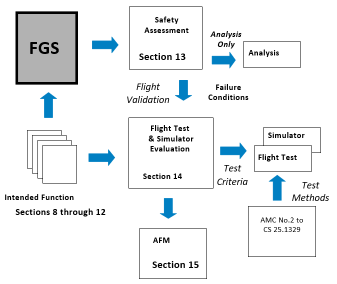
Figure 14-1
14.1 Performance Demonstration
(Fault Free) – CS 25.1301
The
Certification Plan should identify the specific functionality provided by the
FGS. The flight test and/or simulator program will typically assess this
functionality under representative operational conditions including applicable
aeroplane configurations and a representative range of aeroplane weight,
centre of gravity and operational envelope.
The
performance of the FGS system in each of its guidance and control modes should
be evaluated. The acceptability of the
performance of the FGS may be based on test pilot assessment, taking into
account the experience acquired from similar equipment capabilities, and the
general behaviour of the aeroplane. The level of acceptable performance may
vary according to aeroplane type and model. The FGS should be evaluated for
its low and high manoeuvring capability. AMC No.2 to CS 25.1329 may provide additional information on FGS test procedures.
The
acceptability of mode controls and annunciations, any associated alerts and
general compatibility with cockpit displays should be evaluated. The FGS should be free from unexpected
disengagement and confusion resulting from changing FGS modes. Additional
considerations relating to the assessment of Human Factors is provided in
Section 14.5.
Normal
performance is considered to be performance during operations well within the
aeroplane’s flight envelope and with routine atmospheric and environmental
conditions. Normal performance should
be demonstrated over a range of conditions that represent typical conditions
experienced in operational use.
The FGS
should be evaluated to determine the acceptability of the following
characteristics:
—
The
stability and tracking of automatic control elements
—
The
flyability and tracking of guidance elements
—
The
acquisition of flight paths for capture modes
—
Consistency
of integration of modes (Section 12)
Performance
should be assessed in the presence of errors that can reasonably be expected
in operation (e.g., mis-selection of approach speed).
14.1.2 Rare Normal Performance
Rare normal
performance is considered to be performance of the system under conditions
that are experienced infrequently by the aeroplane during operational use.
These conditions may be due to significant environmental conditions (e.g.,
significant wind, turbulence, etc.) or due to non-routine operating conditions
(e.g., out-of-trim due to fuel imbalance or under certain ferry
configurations, or extremes of weight and c.g. combinations). Specific rare
normal conditions are discussed below
The test
program should assess the FGS performance in more challenging operational
environments e.g., winds, wind gradients, various levels of turbulence. Rare
environmental conditions may require the FGS to operate at the limits of its
capabilities. The intent of the evaluation is to assess the performance of the
FGS under more demanding conditions that may be experienced infrequently
in-service.
Due to the
severity of some environmental conditions, it is not recommended, or required,
that the FGS flight evaluations include demonstration in severe and extreme turbulence,
or include flights into a microburst. These conditions are more appropriately
addressed by simulator evaluation.
The FGS
should be evaluated to determine the acceptability of the following
characteristics:
—
The
stability of automatic control elements and ability to resume tracking
following any upset
—
The
flyability of guidance elements and ability to resume tracking following any
upset
—
The
acceptability of mode transitions and overall cockpit system integration.
The
implications of continued use of the automatic flight control elements of the
FGS in icing conditions should be assessed. Ice accumulation on the aeroplane
wings and surfaces can progressively change the aerodynamic characteristics
and stability of the aeroplane. Even though the FGS may perform safely under
these conditions, its continued use may mask this change which in turn can
lead to pilot handling difficulties and potential loss of control, should the
autopilot become disengaged (either automatically or manually).
A test
program should assess the potential vulnerability of the FGS to icing
conditions by evaluating autopilot performance during ice shape tests or
during natural icing tests. Sufficient autopilot testing should be conducted
to ensure that the autopilot's performance is acceptable.
In general,
it is not necessary to conduct an autopilot evaluation that encompasses all
weights, centre of gravity positions (including lateral asymmetry), altitudes
and deceleration device configurations. However, if the autopilot performance
with ice accretion shows a significant difference from the non-contaminated
aeroplane, or testing indicates marginal performance, additional tests may be
necessary.
FGS
performance and safety in icing conditions should be demonstrated by flight
test and/or simulation tests, supported by analysis where necessary.
If
significant autopilot inputs are required to compensate for the icing
conditions, then the acceptability of the indication of a significant out of
trim condition should be made and the subsequent response of the aeroplane
when the autopilot disengages (manual or automatic) should be determined
(Refer to Sections 8.1.2 and 9.3.3).
If the
aeroplane is configured with a de-icing system, the autopilot should
demonstrate satisfactory performance during the shedding of ice from the
aeroplane.
Where
degradation is noted which is not significant enough to require changes to the
autopilot system or to de-icing/anti-icing systems, appropriate limitations
and procedures should be established and presented in the AFM.
If the FGS provides windshear escape guidance,
performance demonstration requirements should be conducted consistent with FAA
AC 25-12.
14.1.2.3 Indication and Response to
an Out of Trim Condition
An
assessment should be performed to determine the acceptability of the out of
trim annunciation and subsequent response to disengagement (Refer to Section
9.3.3).
14.1.3 Specific Performance
Conditions
The
following paragraphs identify specific performance conditions requiring
evaluation by flight test and/or simulation.
The FGS
should be assessed for the acceptability of the low speed protection
performance under the following conditions:
—
High
Altitude Cruise with a simulated engine failure.
—
Climb
to Altitude Capture at Low Altitude with a simulated engine failure during
capture
—
Vertical
Speed with insufficient climb power
—
Approach
with speed abuse
14.1.3.2 High-speed Protection
The FGS
should be assessed for the acceptability of the high-speed protection
performance under the following conditions:
—
High
altitude level flight with Autothrust function
—
High
altitude level flight without Autothrust function
—
High
altitude descending flight with Autothrust function
The
objective of the go-around mode (refer to Section 11.3.2) is to quickly change
the flight path of the aeroplane from approach to landing to a safe climbout
trajectory. The mode has specific utility in low visibility conditions when
operations are predicated on a decision altitude/height (DA/H) and a go-around
is necessary if visual references are not acquired at the DA/H. Therefore, the
assessment of the go-around mode may be conducted in conjunction with the
evaluation of the FGS to support low visibility operations, using additional
criteria contained in FAA AC 120-28D, AC 120-29A and CS AWO Subparts 2 or 3.
The flight
evaluation should be conducted to assess the rotation characteristics of the
aeroplane and the performance of the aeroplane in acquiring and maintaining a
safe flight path. The acceptability of the operation if contact is made with
the runway during the missed approach or balked landing should be established.
A
demonstration program should be established that confirms acceptable operation
when the following factors are considered:
—
Aeroplane
weight and CG
—
Various
landing configurations
—
Use
of manual thrust or autothrust
—
Consequences
of thrust de-rates with selection of Go around mode
—
An
Engine Failure at the initiation of Go-around
—
An
Engine failure during GA – after go-around power is reached
—
Initiation
altitude (e.g., in ground effect or not, during flare)
The
following characteristics should be evaluated:
—
The
pitch response of the aeroplane during the initial transition
—
Speed
performance during aeroplane reconfiguration and climbout
—
Integrated
autopilot and autothrust operation
—
Transition
to Missed Approach Altitude
—
Lateral
performance during an engine failure
Where height
loss during a go-around manoeuvre is significant or is required to support
specific operational approval, demonstrated values for various initiation
heights should be included in the AFM.
14.1.3.4 Steep Approach (Special Authorization)
Typical
approach operations include glidepath angles between 2.5 and 3.5 degrees.
Application for approval to conduct operations on glidepath angles of greater
than 3.5 degrees requires additional evaluation. For such an approval, the FGS
flight test and simulator demonstration should include:
—
Approach
path capture, tracking and speed control
—
Recovery
of the system from abuse cases e.g. glidepath angle and speed
—
Assessment
of autopilot disengagement transient
—
Demonstration
of go-around mode from a Steep Approach
For
autopilot use at approach angles greater than 4.5 degrees the applicant is
recommended to contact EASA for the applicable Special Condition criteria
14.1.4 Flight Director / HUD Considerations
The guidance
aspect of an FGS may be provided by a head down Flight Director (F/D) or by a
Head-Up Display (HUD) system. F/D’s can utilize various guidance cues (e.g.,
cross pointer, single cue, flight path vector, etc.) whilst HUD’s typically
use a symbology linked to a flight path vector. The guidance elements may have
a fixed aeroplane reference (e.g., the traditional F/D) or may use a moving
reference such as a flight path vector. Various new display mediums are
evolving (e.g., EVS and SVS) that may integrate guidance elements with
situational elements.
The flight
test or simulator program should demonstrate that the F/D or HUD guidance
elements provide smooth, accurate and damped guidance in all applicable modes,
so as to achieve satisfactory control task performance without pilot
compensation or excessive workload.
The flight
director guidance should provide adequate performance for operations with:
—
stability
augmentation off
—
alternate
fly-by-wire control modes (e.g., direct law), if any
—
an
engine inoperative.
Some pilot
compensation may be acceptable for these conditions
Flight
directors designed to work with a non-stationary tracking reference (such as a
flight path angle or flight path vector which are commonly used with HUD
guidance) should be evaluated in conditions which bring these guidance symbols
to the field of view limits of the display. Crosswinds, and certain
combinations of airspeed, gross weight, centre of gravity and flap/slat/gear
configurations might cause such conditions. At these limits, the dynamics of
the guidance response to pilot control inputs can differ with potentially
adverse affects on tracking performance, pilot compensation and workload.
Movement of
the flight director and its tracking reference should also be demonstrated not
to interfere with primary instrument references throughout their range of
motion. The pilot’s ability to interpret the guidance and essential flight
information should not be adversely affected by the movement dynamics or range
of motion.
14.1.4.1 Specific Demonstrations for Head-Up Display
These
demonstrations are intended to show compliance with the following paragraphs
of this AMC:
—
Section
8.2 Flight Director
Engagement/Disengagement and Indications, with its subparagraphs
—
Section
9.2 Flight Guidance Mode Selection,
Annunciation and Indication
—
Section
9.4 FGS Considerations for Head-Up
Displays (HUD)
—
Section
10.1 Normal Performance (specifically
criteria for flight director guidance)
When the
pilot flying (PF) is using the HUD, the HUD is where the pilot is looking for
the basic flight information and the pilot is less likely to be scanning the
head down instruments. Therefore:
—
It
should be demonstrated that the location and presentation of the HUD
information (e.g., guidance, flight information and alerts/annunciations) does
not distract the pilot or obscure the pilot’s outside view. For example, the
pilot should be able to track the guidance to the runway without having the
view of runway references or hazards along the flight path obscured by the HUD
symbology.
—
It
should be demonstrated that pilot awareness of primary flight information,
annunciations and alerts is satisfactory when using any HUD display mode. Some
display modes that are designed to minimize “clutter” could degrade pilot
awareness of essential information. For example, a “digital-only” display mode
may not provide sufficient speed and altitude awareness during high-speed
descents.
—
It
should be demonstrated that the pilot could positively detect cases when
conformal symbology is field of view limited.
—
Approach
mode guidance, if provided, should be satisfactory throughout the intended
range of conditions, including at the minimum approach speed and maximum
crosswind, with expected gust components, for which approval is sought.
—
It
should be demonstrated that visual cautions and warnings associated with the
flight guidance system can be immediately detected by the pilot flying while
using the HUD.
—
It
should be demonstrated that the pilot flying can immediately respond to
windshear warnings, ground proximity warnings, ACAS/TCAS warnings, and other
warnings requiring immediate flight control action, such as a go-around, while
using the HUD without having to revert to a head down flight display.
In certain
phases of flight, it is important from a flight crew coordination standpoint
that the pilot not flying (PNF) be aware of problems with the HUD used by the
PF. Therefore it should also be demonstrated that the PNF could immediately be
made aware of any visual cautions and warnings associated with the HUD for
applicable phases of flight.
If approach
mode guidance is provided, satisfactory performance should be demonstrated
throughout the intended range of operating conditions for which approval is
sought e.g. at the minimum approach speed and maximum crosswind, with expected
gust components.
If recovery
guidance is provided, it should be demonstrated that the pilot could
immediately detect and recover from unusual attitudes when using the HUD.
Specialized unusual attitude recovery symbology, if provided, should be shown
to provide unequivocal indications of the attitude condition (e.g.,
sky/ground, pitch, roll, and horizon) and to correctly guide the pilot to the
nearest horizon. The stroke presentation of flight information on a HUD may
not be as inherently intuitive for recognition and recovery as the
conventional head down attitude display (e.g., contrasting colour, area fill,
shading vs. line strokes). The HUD display design needs to be able to
compensate for these differences to provide adequate pilot recognition and
recovery cues.
14.1.4.2 Simulator Demonstration for Head-Up Display (HUD)
If a
pilot-in-the-loop flight simulation is used for some demonstrations, then a
high fidelity, engineering quality facility is typically required. The level
of simulator may vary with the functionality being provided and the types of
operation being conducted. Factors for validation of the simulation for
demonstration purposes include the following:
—
guidance
and control system interfaces
—
motion
base suitability
—
adequacy
of stability derivative estimates used
—
adequacy
of any simplification assumptions used for the equations of motion;
—
fidelity
of flight controls and consequent simulated aircraft response to control
inputs
—
fidelity
of the simulation of aircraft performance
—
adequacy
of flight deck instruments and displays
—
adequacy
of simulator and display transient response to disturbances or failures (e.g.,
engine failure, auto-feather, electrical bus switching)
—
visual
reference availability, fidelity, and delays
—
suitability
of visibility restriction models such as appropriate calibration of visual
references for the tests to be performed for day, night, and dusk conditions
as necessary
—
fidelity
of any other significant factor or limitation relevant to the validity of the
simulation.
Adequate
correlation of the simulator performance to flight test results should be
made.
14.1.5 Flight Crew Override of
the Flight Guidance System
A flight
evaluation should be conducted to demonstrate compliance with Section 8.4. The
flight evaluation should consider the implication of system configuration for
various flight phases and operations.
Effect of
flight crew override should be assessed by applying an input on the cockpit
controller (control column, or equivalent) to each axis for which the FGS is
designed to disengage, i.e. the pitch and roll yoke, or the rudder pedals (if
applicable).
If the
autopilot is designed such that it does not automatically disengage due to a
pilot override, verify that no unsafe conditions are generated due to the
override per Section 8.4. The evaluation should be repeated with progressively
increasing rate of force application to assess FGS behaviour. The effects of
speed and altitude should be considered when conducting the evaluation.
If the
design of the autopilot provides for multiple channel engagement for some
phases of flight that results in a higher override force, these conditions
should be evaluated.
The
capability of the flight crew to override the autothrust system should be
conducted at various flight phases. The evaluation should include an override
of the autothrust system with a single hand on the thrust levers while
maintaining control of the aeroplane using the opposite hand on the control
wheel (or equivalent). This action should not result in an unsafe condition
per Section 8.4, either during the override or after the pilot releases the
thrust levers. If the autothrust system automatically disengages due to the
override, the alerts that accompany the disengagement should be assessed to
ensure flight crew awareness.
14.1.5.3 Pitch Trim System
Evaluation during an Autopilot Override
The effect of flight crew override
during automatic control on the automatic trim systems should be conducted.
The pilot should then apply an input to the pitch cockpit controller (i.e.,
control column or sidestick) below that which would cause the autopilot to
disengage and verify that the automatic pitch trim system meets the intent in
Section 8.4.
If the system design is such that
the autopilot does not have an automatic disengagement on override feature,
the pilot should initiate an intentional override for an extended period of
time. The autopilot should then be disengaged, with the Quick Disconnect
Button, and any transient response assessed in compliance with Section 8.4.
The effectiveness and timeliness of any Alerts used to mitigate the effects of
the override condition should be assessed during this evaluation.
14.2 Failure Conditions Requiring Validation – CS 25.1309
The Safety
Assessment process identified in Section 13 should identify any Failure
Condition responses that would require pilot evaluation to assess the severity
of the effect, the validity of any assumptions used for pilot recognition and
mitigation. The classification of a Failure Condition can vary according to
flight condition and may need to be confirmed by simulator or flight test.
This section
provides guidance on the test criteria, including recognition considerations,
for flight evaluation of these Failure Conditions. In addition, certain
probable failures should be demonstrated to assess the performance of the FGS
and the adequacy of any applicable flight crew procedures.
AMC No. 2 to CS 25.1329, Flight Testing of Flight Guidance
Systems, provides guidance on test methods for particular types of Failure
Condition that have been identified by the Safety Assessment.
The Safety
Assessment described in Section 13 establishes the FGS Failure Condition for
which appropriate testing should be undertaken. Assessment of Failure Conditions has four
elements:
—
Failure
Condition insertion
—
Pilot
recognition of the effects of the Failure Condition
—
Pilot
reaction time; i.e., the time between pilot recognition of the Failure
Condition and initiation of the recovery
—
Pilot
recovery
Failure
Conditions of the autopilot including, where appropriate, multi-axis failures
and automatic-trim failures, should be simulated such that when inserted
represents the overall effect of each Failure Condition.
Where
necessary, Flight Director Failure Conditions should be validated in
accordance with the criteria for the respective phase of flight.
The flight
conditions under which the failure condition is inserted should be the most
critical (e.g., centre of gravity, weight, flap setting, altitude, speed,
power or thrust). If an autothrust system is installed, the tests should be
performed with the autothrust system engaged or disengaged whichever is the
more adverse case.
The pilot
may detect a Failure Condition through aeroplane motion cues or by cockpit
flight instruments and alerts. The specific recognition cues will vary with
flight condition, phase of flight and crew duties.
a) Hardover – the recognition point should
be that at which a pilot operating in non-visual conditions may be expected to
recognize the need to take action. Recognition of the effect of the failure
may be through the behaviour of the aeroplane (e.g., in the pitch axis by
aircraft motion and associated normal acceleration cues and in the roll axis
by excessive bank angle), or an appropriate alerting system. Control column or
wheel movements alone should not be used for recognition. The recognition time
should not normally be less than 1 second.
If a recognition time of less than 1 second is asserted, specific
justification will be required (e.g. additional tests to ensure that the time
is representative in the light of the cues available to the pilot).
b) Slowover – this type of Failure
Conditions is typically recognized by a path deviation indicated on primary
flight instruments (e.g., CDI, altimeter and vertical speed indicator). It is important that the recognition
criteria are agreed with the regulatory authority. The following identify
examples of recognition criteria as a function of flight phase:
—
En-route
cruise – recognition through the Altitude Alerting system can be assumed for
vertical path deviation. The lateral
motion of the aeroplane may go unrecognised for significant period of time
unless a bank angle alerting system is installed.
—
Climb
and Descent – recognition through increasing/decreasing vertical speed and/or
pitch or roll attitude or heading can be assumed.
—
On
an Approach with vertical path reference - A displacement recognition
threshold should be identified and selected for testing that is appropriate
for the display(s) and failure condition(s) to be assessed.
NOTE:
(1) For an ILS or GLS approach in a
significant wind gradient, a value of 1 dot is considered a reasonable value
for crew recognition. In smooth atmospheric conditions with steady state
tracking, with the vertical flight path typically maintained at less than a
fraction of a needle width, a detection and recognition threshold even below
1/2 dot may be suitable.
(2) For RNAV systems, which do not use dots,
some multiple of needle width, related to an established crew monitoring
tolerance of normal performance may be appropriate (e.g., x needle widths of
deviation on the VNAV scale).
(3) Credit may be taken for excessive
deviation alerts, if available.
—
On
an Approach without vertical path reference – criteria similar to the
climb/descent condition can be assumed.
c) Oscillatory – it is assumed that
oscillatory failures that have structural implications are addressed under CS 25.302.
It can be assumed that the flight crew will disengage the automatic control
elements of the FGS that have any adverse oscillatory effect and will not
follow any adverse oscillatory guidance. However, if there are any elements of
the FGS that can not be disconnected in the presents of an oscillatory Failure
Condition, the long term effects on crew workload and the occupants will need
to be evaluated.
The pilot
reaction time is considered to be dependent upon the pilot attentiveness based
upon the phase of flight and associated duties. The following assumptions are
considered acceptable:
(a) Climb, Cruise, Descent and Holding –
Recovery action should not be initiated until three seconds after the
recognition point
(b) Manoeuvring Flight - Recovery action
should not be initiated until 1 second after the recognition point
(c) Approach - the demonstration of
malfunctions should be consistent with operation in non-visual conditions. The
pilot can be assumed to be carefully monitoring the aeroplane performance and
will respond rapidly once the malfunction has been recognized. A reaction time of 1 second between
recognition point and initiation of recovery is appropriate for this phase of
flight.
NOTE:
(i) For the final phase of landing (e.g.,
below 25 m (80 ft)), the pilot can be assumed to react upon recognition
without delay.
(ii) For phases of flight where the pilot is
exercising manual control using control wheel steering, if implemented, the
pilot can be assumed to commence recovery action at the recognition point.
Pilot
recovery action should be commenced after the reaction time. Following such delay the pilot should be
able to return the aeroplane to its normal flight attitude under full manual
control without engaging in any dangerous manoeuvres during recovery and
without control forces exceeding the values given in CS 25.143 (d). During the
recovery the pilot may overpower the automatic pilot or disengage it.
For the
purpose of determining the minimum height at which the autopilot may be used
during an approach, or for height loss assessments, a representative recovery
appropriate to the aeroplane type and flight condition should be performed.
This manoeuvre should not lead to an unsafe speed excursion to resume a normal
flight path. An incremental normal acceleration in the order of 0.5 g is
considered the maximum for this type of manoeuvre.
The primary
concern for the takeoff phase of flight is the effect of the worst case
Failure Condition, identified by the Safety Assessment, on the net flight of
the aeroplane after takeoff and the aeroplane’s attitude and speed during
climbout. The effects should be evaluated in the pitch up, pitch down and bank
as applicable.
If the FGS
provides on runway guidance for takeoff, the effect of the failures on that
takeoff guidance should be assessed in accordance with CS AWO Subpart 4.
14.2.3 Climb, Cruise, Descent and
Holding
Where the
Safety Analysis identifies a Failure Condition requiring flight/simulator
evaluation with pilot assessment, the height loss should be established in
accordance with the method described in the flight test procedures – see AMC No.2 to CS 25.1329, section 4.2.3.3.
Where the
Safety Analysis identifies a Failure Condition that has a dynamic effect on
the roll control of the aeroplane, the Failure Condition should be introduced
at the bank angle for normal operation. The bank angle should not exceed 60
degrees when the pilot recognition and recover times identified above are
applied.
A discussion
of the operational considerations for approach operations is contained in
Section 14.3. This section identifies
test criteria to support those considerations. The safety assessment process
should identify the demonstration of specific Failure Conditions during the
approach.
The fault
demonstration process during approach should include the four phases
identified in Section 14.2.1. The Failure Condition should be inserted at a
safe but representative height. The deviation profile should be identified and
applied as indicated in the later sections.
14.2.5.1 Approach with Vertical Path Reference
Approach
with vertical path reference includes xLS and RNAV operations.
a) xLS (ILS, MLS, GLS)
ILS and MLS
operations are typically conducted on instrument approach procedures designed
in accordance with United States TERPS or ICAO PANS-OPS criteria, or
equivalent. These criteria together with ICAO Annex 14 are generally intended
to take into account obstacles beneath a reference obstacle identification
surface. It is expected that the same or equivalent criteria will be applied
to GLS operations. Hence, in assessing the implication of the effect of
failures during autopilot operations a reference 1:29 slope penetration
boundary has been applied against the deviation profile to identify an
appropriate altitude for continued autopilot operation. The 1:29 slope has
been found to provide an acceptable margin above obstacles on an approach.
The worst
case Failure Condition identified by the Safety Assessment (see Section 13.4)
should be demonstrated against the deviation profile criteria and a Minimum
Use Height (MUH) established (See AMC No.2 to CS 25.1329, Section 4.2.3.2).
b) RNAV
For RNAV
coupled approach operations, a vertical flight path similar to an xLS flight
path will be used (e.g., 3o path starting 15 m (50 ft) above the
threshold). However, due to sensor
characteristics it is assumed that RNAV operations will be conducted with a
DA(H) or MDA(H) that is higher than an equivalent MUH on an xLS approach to
the same runway. Further, for this type of operation it should be noted that
the MUH is always in the visual segment of the approach, where it is assumed
that the failure recognition and recovery are conducted with the pilot having
established outside visual reference.
In order to
derive only one MUH value for simplicity of use, it is assumed that the
effects of failure on the autopilot in RNAV operation are no worse than for
the xLS operation, and no further determination or demonstration is required.
However, the applicant should show that due account has be taken in the Safety
Assessment of the differences between the RNAV and xLS inputs to the autopilot
(e.g. barometric altitude input, FMS position and guidance commands, and their
failure effects). If these effects can be bounded or otherwise reconciled,
then the xLS demonstrated MUH might also be considered applicable to RNAV
operations.
If these
effects cannot be bounded or accounted for within those for the xLS operation,
the MUH should be determined in accordance with an Approach Without Vertical
Path Reference – see below.
14.2.5.2 Approach Without Vertical Path
Reference
For an
approach without vertical path reference (e.g., VOR, NDB, localizer only) the
FGS mode of operation is typically vertical speed/flight path angle (i.e. a
cruise mode). The worst case Failure Condition for this type of mode should be
demonstrated in the approach configuration, and an appropriate height loss
established in accordance with the method described in AMC No.2 to CS 25.1329, Section 4.2.3.3.
In support of an approval to use
the FGS on glidepath angles of greater than 3.5 degrees (see Section 14.1.3.4)
an assessment should be made of the effects of failure conditions for this
type of operation. For the use of autopilot, an appropriate MUH should be
established in accordance with the deviation profile method described in
Section 14.2.5. For this assessment, the obstacle plane associated with a
nominal 3-degree glidepath angle (1:29 slope) should be adjusted according to
the maximum approach angle, for which approval is sought.
The
following are failure conditions that should be considered as part of the FGS
evaluation program:
—
Engine
Failure during approach - continue approach to DA(H)/MDA(H)
—
The
effect of potential fuel imbalance
—
Aeroplane
System Failures (as necessary – requiring specific flight evaluation), e.g.,
—
Hydraulics
—
Electrical
—
Flight
Controls
—
FGS
related Sensors
The
probability of failure of a FGS element to disengage when the quick disengagement
control is operated should be shown to be acceptable by the Safety Analysis
process. If credit is to be taken for acceptable continued manual operation
with the FGS elements remaining engaged i.e. without operating any of the
other disengagement controls, then a flight demonstration should be conducted
though approach, landing and rollout.
14.3 Criteria Supporting the
Operational Use of an Autopilot
The criteria
contained in this section are intended to identify how the functional
capability of the FGS, established during the certification, can be utilized
to support typical flight operations. The criteria are based on experience
gained from certification programs and functionality provided by traditional
systems. A FGS providing non-traditional functionality, using new or novel
technology, and/or implementation techniques, may require additional criteria
to be established.
14.3.1 Autopilot Operations in close proximity the ground
The minimum
engagement point for the autopilot after takeoff and the minimum use of the
autopilot during approach should take into consideration the effect of:
—
Failures
and their effects (i.e., Failure Conditions),
—
Fault-free
performance,
—
Any
specific operational considerations and/or mitigation.
During low
visibility operations, multiple redundant autopilot channels may be used and
the effect of any autopilot failures on the flight path may be eliminated, or
substantially minimized, by the protection provided be that redundancy. The
following considerations apply primarily to single channel operations where
performance or integrity aspects may require further consideration. See also
Section 13.5.2, which identifies specific considerations relating to autopilot
operations close to the ground in the presence of failures.
14.3.1.1 Autopilot Engagement
Altitude or Height after Takeoff – Failure
Effects
The
potential deviation of the aeroplane from the desired flight path due to the
effect of a Failure Condition may necessitate delaying the engagement of an
autopilot to an acceptable height above the departure runway.
To support
this determination, if an autopilot Failure Condition, or Failure Conditions,
are identified that will cause a significant deviation below the intended
vertical flight path, the worst-case deviation profile should be identified.
This profile and the recovery of the aeroplane should not result in
penetration of the net flight path as defined in CS 25.115.
If the Failure Condition(s) has a neutral effect on the flight path but has
implications for speed control during takeoff, the acceptability of cues for
the flight crew detection of the condition should be made. The effect of any
Failure Condition relating to the bank angle of the aeroplane should also be
assessed. In all of the above, account should be taken of operating the
aeroplane at the WAT limit.
The minimum
engagement height will typically be established based on the greater of the
following considerations:
—
The
lowest altitude or height where the flight crew could reasonably be assumed to
engage the autopilot. Consideration should be given to normal flight crew
tasks during rotation and lift-off (typically 30 m (100 ft) or greater).
—
Any
allowance for the acceptability of the performance of the autopilot during the
basic engagement/mode transition.
—
The
lowest altitude or height consistent with the response of the aeroplane to any
identified autopilot Failure Condition(s).
—
Activation
of stall identification system (e.g. stick pusher) armed (if installed).
If the
response to the worst-case failure condition causes a significant transition
below the intended vertical flight path, the deviation information should be
provided in the AFM.
14.3.1.2 Autopilot Engagement during Approach
The
potential deviation of the aeroplane from the desired flight path due to the
effect of a Failure Condition may necessitate the disengagement of an
autopilot at an appropriate height on the approach to landing.
The
operational minimum engagement height will be established based on the
following considerations:
—
the
altitude or height at which the performance of the automatic control is no
longer acceptable,
—
the
lowest altitude or height consistent with the response of the aeroplane to a
subsequent autopilot failure,
—
any
specific operational consideration.
The
following paragraphs provide assessment criteria for operations that have
guidance to the runway threshold, and for those that do not.
14.3.1.2.1 Approach with Vertical Path
Reference – Failure Effects
Approaches
with vertical path reference can include xLS (i.e., ILS, MLS and GLS) or RNAV.
Operations using xLS, can be assumed to be conducted with respect to a flight
path prescribed or established as an integral part of navigation service
provided by the State of the airport. RNAV approach operations will be
conducted using an onboard database that provides a navigation flight path to
the runway.
The
operational consideration for this type of operations relates an assessment of
the adequacy of continued use of the autopilot in maintaining the desired
vertical flight path. Considerations include the lowest altitude consistent
with the response of the aeroplane to an autopilot failure.
To support
this determination, if an autopilot Failure Condition, or Failure Conditions,
is identified that causes a significant transition below the intended vertical
flight path, the worst-case deviation profile should be identified using the
method identified in Section 14.2.5.1. If the Failure Condition(s) has a
neutral effect on the flight path, the acceptability of cues for the flight
crew detection of the condition should be made. The effect of any Failure
Condition relating to the bank angle of the aeroplane should be assessed.
For the
purpose of the airworthiness assessment, the vertical flight path an xLS and
RNAV approach can be assumed to be a flight path of three degrees that passes
through the runway threshold at an altitude of 15 meters (50 ft).
Considerations for steep approaches are provided in a preceding section.
The vertical
flight path control for an xLS approach will be made with reference to the
path defined by the navigation service. The RNAV vertical flight path will
typically be conducted with reference to barometric altitude. An appropriate
adjustment to the minimum use height may be appropriate to take into account
the vertical accuracy of RNAV operations.
NOTE: Any operational considerations such
as temperature effect compensation should be considered as part of the
operational authorization.
The Minimum
Use Height can be determined using the method identified in AMC No.2 to CS 25.1329, Section 4.2.3.2.
14.3.1.2.2 Approach without Vertical Path
Reference
Flight
operations with no vertical path reference are conducted with an appropriate
visual segment for final approach path. In the interest of providing
appropriate automatic control to assist in a stabilized approach, the minimum
use of the autopilot should be consistent with the performance needed for the
descent (e.g., vertical speed/flight path angle) and the pilot detection and
recovery from an autopilot failure.
To support
this determination, if an autopilot Failure Condition, or Failure Conditions,
is identified that causes a significant transition below the intended vertical
flight path, the worst-case deviation profile should be identified. If the
Failure Condition(s) has a neutral effect on the flight path but has
implications for speed control during takeoff, the acceptability of cues for
the flight crew detection of the condition should be made. The effect of any
Failure Condition relating to the bank angle of the aeroplane should be
assessed.
For FGS that
are failure protected (i.e., fail passive), the minimum engagement height will
typically be no lower than 15 m (50 ft) above runway elevation. However, when
determining this limitation, account should be taken of the handling task
presented to the pilot when regaining manual control, especially in limiting
crosswind conditions.
For FGS that
are not failure protected (i.e., not fail-passive), the demonstrated minimum
use height will typically be established based on the greater of the following
considerations:
a. 15 m (50 ft) above runway elevation
b. Two times the Height Loss for the
aeroplane as a result of any identified autopilot Failure Condition(s) using the method identified in AMC No.2 to CS 25.1329, Section 4.2.3.3.
For the purposes of this AMC, circling
approaches may be considered to have three visual segments associated with the
approach; a segment at or above the minimums prescribed by the procedure that
parallel the runway in the opposite direction of the landing runway, a turning
segment to align with the runway that can be level or partially descending,
and a final descending segment to landing.
Operationally, the autopilot may remain engaged even after leaving the
minimum altitude (MDA(H)) for safety and flight crew workload relief reasons.
This operational procedure should be balanced against unacceptable performance
or failure characteristics. As this procedure is in the visual segment, no
specific constraints for the use of the autopilot are considered necessary for
this phase of flight unless specific unacceptable performance or failure
characteristics related to circling approach are identified during the
certification program.
14.3.2 Climb, Cruise, Descent, and
Holding
The value of
the use of the autopilot in providing flight crew workload relief in climb,
cruise, descent and holding phases of flight should be balanced against the
failure characteristics of the autopilot. No specific constraints for the use
of the autopilot are considered necessary for these phases of flight unless
specific unacceptable performance or failure characteristics are identified
during the certification program, related to climb, cruise, descent or
holding.
No specific
constraints for the use of the autopilot are considered necessary for
manoeuvring flight unless unacceptable performance or failure characteristics
are identified during the certification program. Section 14.2.4 provides
assessment criteria for manoeuvring flight for autopilot failures.
14.4 Automatic Disengagement of
the Autopilot
Automatic
disengagement of the FGS will occur for several reasons such as system
failures, sensor failures, unusual accelerations, etc. The automatic
disengagement characteristics of the FGS should be investigated throughout the
flight envelope. These disengagement cases should be analysed to determine the
ones requiring demonstration during the test program. For each disengagement,
the transients, warnings, and pilot workload for recovery should be evaluated,
and compliance with CS 25.1329 (d) and (e) should be
verified. The use of simulation is recommended for all conditions that are
expected to result in significant transients.
14.5 Assessment of Human Factors Considerations
The evaluation, demonstration and testing should assess the
acceptability of the human-machine interface with the FGS and the potential
for flight crew errors and confusion concerning the behaviour and operation of
the FGS, based on the criteria described in earlier Sections.
The evaluation of normal and non-normal FGS operations should include
the representative range of conditions in terms of crew mental or physical
workload, required crew response timeliness, or potential for confusion or
indecision. The set of test cases should represent operationally relevant
scenarios and the assumptions about pilot training and skill level should be
documented.
Flight evaluation during certification is a final assessment and is
intended to validate the design. Prior evaluations are typically conducted in
a variety of ways and at different levels of fidelity in order to finalize the
design. These may include:
—
Engineering
evaluations and task analyses, including cognitive and physical tasks;
—
Mock-up
evaluations and demonstrations;
—
Part-task
evaluations and demonstrations;
—
Simulator
evaluations, demonstrations, and tests; and
—
Engineering
flight evaluations, demonstrations, and tests.
The data and/or experience from such evaluations may be useful for
credit to establish FGS compliance with regulations having human factors
considerations. In some cases, certification credit or demonstration of
compliance using simulations cannot be granted due to inability to find
simulation conformity. In such cases, certification authorities may consider
that less flight testing may be required to show compliance if the simulation
evaluations have added confidence with respect to the reduced potential for
crew error and confusion and other human factors attributes of the pilot/FGS
interface. Also, applicants have successfully used comparisons to previously
certificated designs to obtain such credit (although such credit is not
assured). Additional testing may be warranted, e.g., for new FGS flight crew
interface designs or functions.
In many cases the evaluation, demonstration and test scenarios,
including failures and environmental events, will determine whether the data
should be obtained in simulation or in flight, because of safety
considerations or unavailability of the necessary environmental conditions. In
some of these cases a very high fidelity simulation will be needed. In addition to the simulation validation
considerations identified in Section 14.1.4.2, the simulation used may need to
include the following features, depending on the functionality of the FGS:
—
Physical
implementation of flight deck controls, displays, indicators and annunciators
for all flight crew positions that are relevant to the objectives of the
evaluation.
—
Adequate
emulations of relevant equipment (hardware and software function, including
capability to introduce failures) should be incorporated in the simulation.
—
Weather
simulation including gusts, turbulence, windshear and visibility.
—
Representation
of the operational environments, including interaction with air traffic
services, day/night operations, etc, as relevant to the functions and pilot
tasks being evaluated
—
Data
collection capabilities
Simulator evaluations and tests are intended to generate objective
and/or subjective data. It may not always be possible or necessary to obtain
quantifiable measurements of flight crew performance, even with high fidelity
flight or simulation evaluation, demonstration, or test scenarios. In these
cases, evaluation procedures should be based on the use of structured,
subjective methods such as rating scales, questionnaires and/or interviews.
When there is dependence on this type of data, evaluations should consider
multiple data collection techniques with an appropriate number of pilot
evaluators.
In order to provide sound evaluations, pilots should be trained
appropriately on the FGS system operation and procedures. They should also
have experience in the kinds of operation and aircraft types for which the FGS
is intended, be familiar with the intended function of the FGS, its
operational and design philosophy, and how this philosophy fits with the
overall flight deck and its operational and design philosophy.
Rationale should be provided for decisions regarding new or unique
features in a design. It should be confirmed that the data resulting from the
evaluations support acceptability of any new or unique features.
The certification planning documentation should describe the means to
show compliance of the Human Factors-related considerations of the FGS, with
this AMC.
15 AEROPLANE
FLIGHT MANUAL (AFM)
The
following sections provide guidance on material to be provided in the
Aeroplane Flight Manual (AFM) to ensure that the appropriate information
related to FGS operation is translated into air carrier operations. For
additional guidance, note that AMC 25.1581 addresses requirements of the AFM
for Large Aeroplanes and distinguishes between those aircraft that are used in
Commercial Air Transportation and those that are not.
The
terminology used in the AFM should be consistent with the intended operational
use.
Appropriate
AFM information related to low-visibility operations is addressed in CS-AWO
Subparts 1-4.
15.1 Information Supporting
Operational Use of the Autopilot
The airworthiness certification process will
assess the effect of autopilot Failure Conditions as identified in Sections 13
and 14. If a specific Minimum Use Height (MUH) is necessary, then the height
should be provided in the Limitations section of the AFM. If the design is
such that the effects of Failure Condition(s) do not require establishment of
a MUH, then the pertinent deviation profile or height loss information should
be provided in the Normal or Non-normal section of the AFM, as applicable.
If MUH or a Height Loss value is applicable,
it should be specified as follows:
(a) Takeoff
- Autopilot Engagement Altitude or Height.
NOTE: If
minimum engagement altitude(s) or height(s) are not specified, then “maximum
displacement deviation” information from a pertinent takeoff flight path and
approach profile should be provided in the AFM Normal Procedures section, or
in the associated Flight Crew Operation Manuals (FCOM).
(b) Cruise
– Height Loss
(c) Approach
- MUH or Height Loss
i) Approach
– with Vertical Path Reference
—
the
MUH should be determined based on clearance above a 1:29 plane using the Deviation Profile Method.
ii) Approach
– without Vertical Path Reference
—
the
Height Loss should be determined using the Height Loss Method
The Limitations section of the AFM presents
those FGS operating limitations appropriate to the aeroplane model as
established in the course of the type certification process, and as necessary
(Ref. CS
25.1581(a)(1) and CS 25.1583). FGS operational limitations (should any exist) should specify, any
configuration/envelope restrictions, if and as applicable.
15.3 Non-normal/Emergency Procedures
The AFM should include Non-normal or Emergency
procedures appropriate to the FGS identified during the certification program
(Ref. CS
25.1581(a)(1), CS 25.1585(a)(2) and CS 25.1585(a)(3)).
In lieu of specification of minimum engagement
altitude(s) or height(s) (see Section 15.1 above)), the AFM may alternately specify
“maximum displacement deviations” from a specified takeoff flight path, or
from a specified approach profile. This information may be based on typical
departure or approach flight paths suited for the aircraft type and for
failure conditions that are determined applicable to the type of FGS system
and modes suitable for use.
The flight manual should include any necessary
procedures for the use of the flight guidance system in icing conditions
(including severe icing conditions). In particular, the procedures should
include any necessary changes in operating speeds required either
operationally or as a result of relevant design features of the speed
protection function of the FGS; e.g., variations in minimum speeds as a
function of de/anti-icing system selection; speed increments during approach
and landing in turbulence.
15.4.1 Aircraft with Published Flight Crew Operation
Manuals
The AFM’s
for aircraft for which the manufacturer has published a FCOM should contain
essential information on normal operating procedures that are considered
“peculiar” to the operation of the FGS for the aircraft type or are otherwise
necessary for safe operation (Ref. CS 25.1581(a)(2) and CS 25.1585(a)(1)). FGS description and integration with the overall flight deck design
philosophy; specification and operational procedures that are normally
associated with flight guidance systems should be made available for inclusion
in the FCOM.
If
applicable, a FCOM may contain the “maximum displacement deviation”
information described in Section 15.1, above, in
either numeric or graphic form.
15.4.2 Aircraft without Published
FCOM’s
For aircraft
that rely on the AFM as the sole operating manual, the AFM must contain
operating information sufficient for flight crew reference (Ref. CS 25.1581(a)(2)). FGS description and integration with the overall flight deck design
philosophy, specification and operational procedures that are normally
associated with flight guidance systems should be made available so that an
appropriately trained flight crew may operate the FGS under normal conditions.
[Amdt
25/4]
[Amdt
25/11]
[Amdt
25/12]
[Amdt
25/16]
[Amdt
25/18]
[Amdt
25/26]