AMC No.2 to CS 25.1329 Flight Testing of Flight Guidance Systems
ED
Decision 2007/020/R
Some aspects
of a Flight Guidance System (FGS) design may be validated by laboratory
testing or by simulation, other aspects may necessitate test pilot expertise
and subjective judgment in a representative aircraft environment. The purpose
of this AMC is to provide FGS flight test procedures without specifying the
test means to be used, i.e. actual aircraft or representative flight
simulator.
A flight
test program should be established that confirms the performance of the FGS
for the modes of operation and the operational capabilities supported by its
design. The operational implications of certain failures and Failure
Conditions may require flight evaluation. The pilot interface with FGS
controls and displays in the cockpit should also be assessed.
The scope of
the flight demonstration program will be dependent on the operational
capability being provided including any new and novel features. Early
coordination with the regulatory authorities is recommended to reduce
certification risks associated with the flight demonstration program.
The intent
of the flight demonstration program is to confirm that the operation of the
FGS is consistent with its use for the intended flight operations of the
aeroplane type and configuration.
The modes of
the FGS should be demonstrated in representative aeroplane configurations and
under a representative range of flight conditions.
The
following are specific test procedure that can assist in that demonstration
program. The procedures should be read in conjunction with Sections 10, 11 and
14 of AMC No. 1 to CS 25.1329.
2. Protection Features
Protection
feature are included in the design of an FGS to assist the flight crew in
ensuring that boundaries of the flight envelope or operational limits are not
exceeded leading to an unsafe condition. The means to alert the flight crew to
a condition or for the system to intervene to preclude the condition may vary
but certain operational scenarios can be used to assess the performance of the
system in providing the protection function. The following procedures can be
used to evaluate the protection functions of an FGS.
The low
speed protection feature in an FGS is intended to prevent loss of speed to an
unsafe condition (Refer to AMC No. 1 to CS 25.1329 – Section 10.4.1). This may
be accomplished by a number of means but should be evaluated under a number of
scenarios.
There are
four cases that should be considered when evaluating when the Low Speed
Protection function of a FGS:
1. High Altitude Cruise Evaluation.
(a) At high altitude at normal cruise speed,
engage the FGS into an Altitude Hold mode and a Heading or LNAV mode.
(b) Engage the autothrust into a speed mode.
(c) Manually reduce one engine to idle
thrust.
(d) As the airspeed decreases, observe the FGS
behaviour in maintaining altitude and heading/course.
(e) When the Low Speed Protection condition
becomes active, note the airspeed and the associated aural and visual alerts
including possible mode change annunciations for acceptable operation.
2. Altitude Capture Evaluation at Low
Altitude.
(a) At about 1000 m (or 3000 ft) MSL and 460
km/h (or 250 kt), engage the FGS into Altitude Hold and a Heading or LNAV
mode.
(b) Engage the autothrust into a speed mode.
(c) Set the Altitude Pre-selector to 2500 m
(or 8000 ft) MSL.
(d) Make a flight level change to 2500 m (or
8000 ft) with a 460 km/h (250 kt) climb at maximum climb power.
(e) When the FGS first enters the altitude
capture mode, retard an engine to idle power.
(f) As the airspeed decreases, observe the
aeroplane trajectory and behaviour.
(g) When the Low Speed Protection condition
becomes active, note the airspeed and the associated aural and visual alerts
including possible mode change annunciations for acceptable operations.
3. High Vertical Speed Evaluation.
(a) Engage the FGS in Vertical Speed Mode with
a very high rate of climb.
(b) Set the thrust to a value that will cause
the aeroplane to decelerate at about 1.8 km per second (1 knot per second).
(c) As the airspeed decreases, observe the
aeroplane trajectory and behaviour.
(d) When the Low Speed Protection condition
becomes active, note the airspeed and the associated aural and visual alerts
including possible mode change annunciations for acceptable operation.
4. Approach Evaluation.
(a) Conduct an instrument approach with
vertical path reference.
(b) Couple the FGS to the localizer and
glideslope (or LNAV/VNAV, etc.).
(c) Cross the Final Approach Fix/Outer Marker
at a high-speed (approximately Vref + 74 km/h (40 kt)) with the thrust at idle
power until low speed protection activates.
(d) As the airspeed decreases, observe the
aeroplane trajectory and behaviour.
(e) When the Low Speed Protection condition
becomes active, note the airspeed and the associated aural and visual alerts
including possible mode change annunciation for acceptable operation.
(f) Note the pilot response to the alert and
the recovery actions taken to recover to the desired vertical path and the
re-capture to that path and the acceleration back to the desired approach
speed.
NOTE: If
the FGS remains in the existing mode with reversion to Low Speed Protection,
the FGS should provide a suitable alert to annunciate the low speed condition.
In this case, note the pilot response to the alert and the recovery actions
taken to maintain the desired vertical path and to accelerate back to the
desired approach speed.
The
high-speed protection feature in an FGS is intended to prevent a gain in
airspeed to an unsafe condition (Refer to AMC No. 1 to CS 25.1329 – Section
10.4.2). This may be accomplished by a
number of means but should be evaluated under a number of scenarios.
There are
three cases that should be considered when evaluating the High-speed
protection function of a FGS:
1. High Altitude Level Flight Evaluation
with Autothrust function
(a) Select Autothrust Off (if an automatic
wake-up function is provided; otherwise, select Autothrust on).
(b) Engage the FGS in altitude hold.
(c) Select a thrust level that will result in
acceleration beyond VMO/MMO.
(d) As the airspeed increases, observe the
behaviour of the High-speed protection condition and any autothrust
reactivation and thrust reduction, as applicable.
(e) Assess the performance of the FGS to
control the airspeed to VMO/MMO, or other appropriate speed.
2. High Altitude Level Flight Evaluation
without Autothrust function
(a) Select a thrust value that will result in
acceleration beyond VMO/MMO.
(b) As the airspeed increases, observe the
basic aeroplane overspeed warning activate between VMO + 1 and VMO + 11 km/h
(6 kt).
(c) Observe the high-speed protection
condition become active as evidenced by the unique visual alert and note
possible FGS mode change.
(d) Maintain the existing thrust level and
observe the aeroplane depart the selected altitude.
(e) After sufficient time has elapsed to
verify and record FGS behaviour has elapsed, reduce the thrust as necessary to
cause the aeroplane to begin a descent.
(f) Observe the FGS behaviour during the
descent and subsequent altitude capture at the original selected altitude.
3. High Altitude Descending Flight
Evaluation with Autothrust function
(a) Select Autothrust Off (with automatic
wake-up function) with thrust set to maintain airspeed 10% below VMO/MMO with
the FGS engaged in altitude hold.
(b) Select vertical speed mode that will
result in acceleration beyond VMO/MMO.
(c) As the airspeed increases observe the
autothrust function reactivate and reduce thrust towards idle.
(d) Observe the activation of FGS high-speed
protection condition.
(e) Observe the reduction in pitch.
GENERAL NOTE: If the FGS remains in the
existing mode with reversion to High Speed Protection, the FGS should provide
a suitable alert to annunciate the high-speed condition. In this case, note
the pilot response to the alert and the recovery actions taken to maintain the
desired vertical path and to decelerate back to the desired speed.
3. Environmental
Conditions
Some
environmental conditions have created operational problems during FGS
operations. It should be the objective of the flight demonstration program to
expose the FGS to a range of environmental conditions as the opportunity
presents itself. These include winds, windshear, mountain-wave, turbulence,
icing, etc. However, some specific test conditions may have to be created to
emulate operational conditions that are not readily achieved during normal
flight test.
The
accumulation of ice on the wing and airframe can have an effect on aeroplane
characteristics and FGS performance. FGS operations may mask the onset of an
aeroplane configuration that would present the pilot with handling
difficulties when resuming manual control, particularly following any
automatic disengagement of the FGS.
During the
flight test program the opportunity should be taken to evaluate the FGS during
natural icing conditions including the shedding of the ice, as applicable.
It is
recommended that the opportunity should be taken to evaluate the operation of
the FGS during basic aeroplane evaluation with ‘ice shapes’.
The
following conditions should be considered for evaluating FGS performance under
‘icing conditions’:
(a) "Holding ice" as defined by
CS-25 Appendix C
(b) Medium to light weight, symmetric fuel
loading
(1) High lift devices retracted configuration:
Slow down at 1.8 km per second (1
knot per second) to automatic autopilot disengage, stall warning or entry into
speed protection function.
Recovery should be initiated a
reasonable period after the onset of stall warning or other appropriate
warning. The aeroplane should exhibit no hazardous characteristics.
(2) Full Instrument Approach:
If the
autopilot has the ability to fly a coupled instrument approach and go-around,
it should demonstrate the following:
(i) Instrument approach using all normal flap
selections.
(ii) Go-around using all normal flap
selections.
(iii) Glideslope capture from above the
glidepath.
(3) If the aeroplane accretes or sheds ice
asymmetrically it should be possible to disengage the autopilot at any time
without unacceptable out of trim forces.
(4) General manoeuvrability including normal
turns, maximum angle of bank commanded by the FGS in one direction and then
rapid reversal of command reference to the maximum FGS angle of bank in the
other direction.
The test method for most Failure
Conditions will require some type a fault simulation technique with controls
that provide for controlled insertion and removal of the type of fault
identified as vulnerability. The insertion point will typically be at a major
control or guidance point on the aeroplane (e.g., control surface command,
guidance command, thrust command).
The implication of the effect of the
Failure Condition on various flight phases should be assessed and the
demonstration condition established. This assessment should identify the
parameters that need to be measured and the instrumentation required.
The role of any monitoring and
alerting in the evaluation should be identified.
The alertness of the crew to certain
aeroplane response cues may vary with phase of flight and other
considerations. Guidance on this is provided below.
The ‘success criteria’ or operational
implications should be identified and agreed with the regulatory authority
prior to the conduct of the test. Guidance on this is provided below.
4.2 Fault
Recognition and Pilot
Action
The Safety
Assessment process may identify a vulnerability to the following types of
Failure Condition:
—
hardover
—
slowover
—
oscillatory
The various
types of effect will cause differing response in the aeroplane and resultant
motion and other cues to the flight crew to alert them to the condition. The
flight crew attention may be gained by additional alerting provided by systems
on the aeroplane. The recognition is then followed by appropriate action
including recovery.
The
assessment of the acceptability of the Failure Condition and the validation of
the Safety Assessment assumptions are complete when a stable state is reached
as determined by the test pilot.
The
following paragraphs provide guidance for specific phases of flight.
This
material addresses the use of an FGS after rotation for takeoff.
Section 13
of AMC No. 1 to CS 25.1329 identifies the key considerations for this phase of
flight to be the effect on the net flight path and the speed control after
lift-off. Automatic control is not typically provided for the takeoff roll. It
may however be selected soon after lift-off. Failure Conditions may be
introduced with this engagement.
For the
initial lift-off through flap retraction, it can be assumed that the flight
crew is closely monitoring the aeroplane movements and a maximum crew response
time after recognition would be 1 second.
4.2.2 Climb,
Cruise, Descent and Holding and Manoeuvring
The
demonstration of applicable failure conditions during these phases of flight
would include the potential for occupants to be out of their seats and moving
about the cabin.
There are
two types of approach operations to consider – an approach with and without
vertical path reference. The approach with vertical path reference will be
assessed against ground-based criteria using a deviation profile assessment. A
height loss assessment is used for approaches without vertical path reference.
4.2.3.1 Fault Demonstration Process
The
worst-case malfunction has first to be determined, based on factors such as:
i) Failure Conditions identified by the
system safety assessment.
ii) System characteristics such as
variations in authority or monitor operation.
iii) Mitigation provided by any system alerts.
iv) Aircraft flight characteristics relevant
to failure recognition.
Once the
worst-case malfunction has been determined, flight tests of the worst-case
malfunction should be flown in representative conditions (e.g. coupled to an
ILS), with the malfunction being initiated at a safe height. The pilot should
not initiate recovery from the malfunction until 1 second after the
recognition point. The delay is intended to simulate the variability in
response to effectively a “hands off” condition. It is expected that the pilot
will follow through on the controls until the recovery is initiated.
4.2.3.2 Assessment – Approach with Vertical
Path Reference
Figure 1
provides a depiction of the deviation profile method. The first step is to
identify the deviation profile from the worst-case malfunction. The next step
is to ‘slide’ the deviation profile down the glidepath, until it is tangential
to the 1:29 line or the runway. The Failure Condition contribution to the
Minimum Use Height may be determined from the geometry of the aircraft wheel
height determined by the deviation profile, relative to the 1:29 line
intersecting a point 4.5 m (15 ft) above the threshold. The method of
determination may be graphical or by calculation.
NOTE: The Minimum Use Height is based on the
recovery point because:
i) It is assumed that in service the pilot
will be “Hands off” until the autopilot is disengaged at the Minimum Use
Height in normal operation.
ii) The test technique assumes a worst case
based on the pilot being “Hands off” from the point of malfunction initiation
to the point of recovery.
iii) A failure occurring later in the approach
than the point of initiation of the worst case malfunction described above is
therefore assumed to be recovered earlier and in consequence to be less
severe.
4.2.3.3 Assessment – Approach without Vertical
Path Reference
Figure 2
provides a depiction of the height loss method. A descent path of three
degrees, with nominal approach speed, should be used unless the autopilot is
to be approved for significantly steeper descents. The vertical height loss is
determined by the deviation of the aircraft wheel height relative to the
nominal wheel flight path.
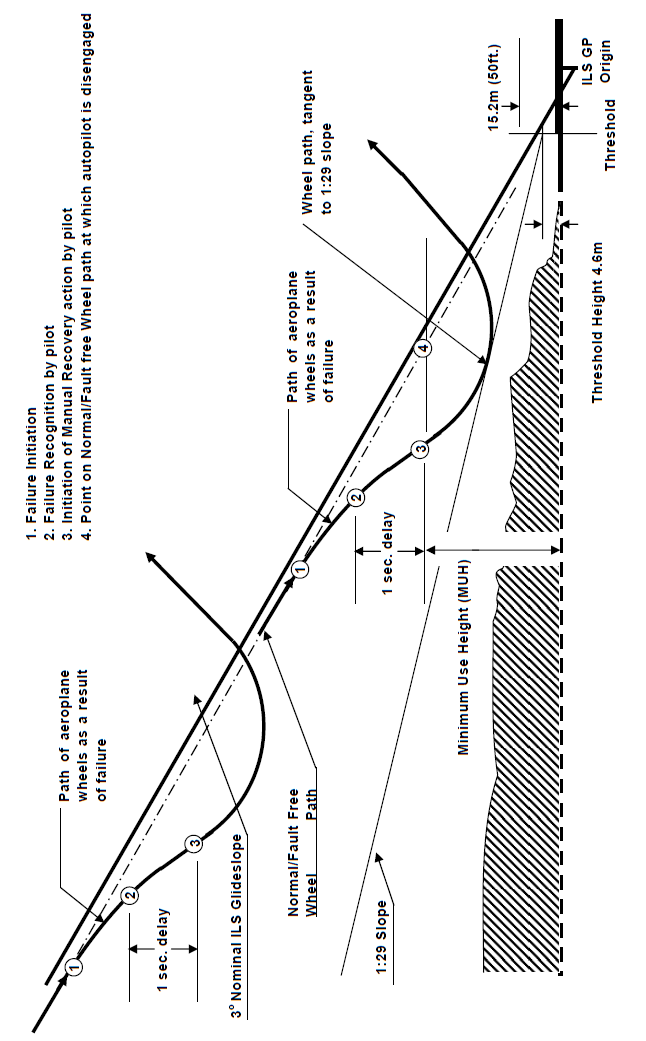
Figure FT-1: Deviation Profile Method
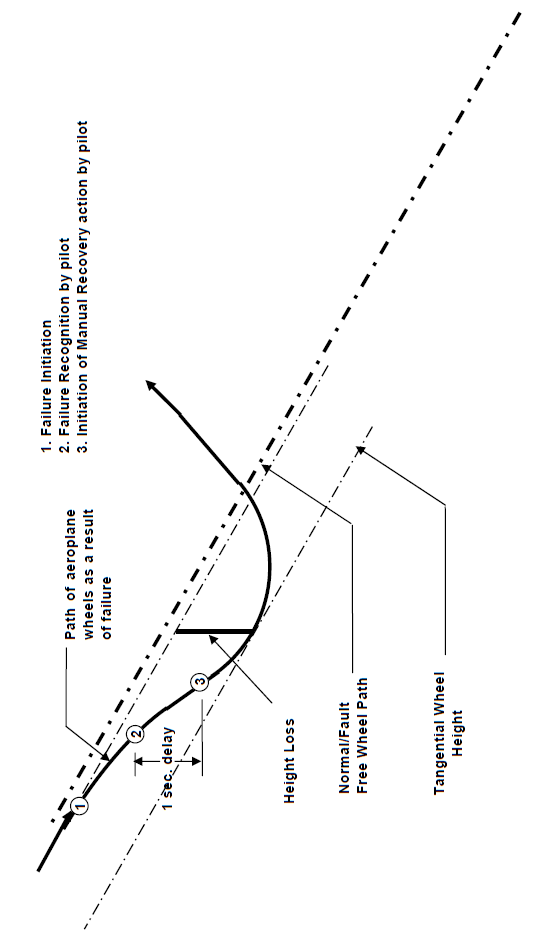
Figure FT-2: Height Loss Method
4.3 Autopilot Override
The initial
tests to demonstrate compliance should be accomplished at an intermediate
altitude and airspeed e.g. 4500 m (15000 ft) MSL and 460 km/h (250 kt). With
the autopilot engaged in altitude hold, the pilot should apply a low force
(sustained and incremental) to the control wheel (or equivalent) and verify
that the automatic trim system does not produce motion resulting in a
hazardous condition. The pilot should then gradually increase the applied
force to the control wheel (or equivalent) until the autopilot disengages.
When the autopilot disengagement occurs, observe the transient response of the
aeroplane. Verify that the transient response is in compliance with Section
8.4 of AMC No. 1 to CS 25.1329.
Disengagement
caused by flight crew override should be verified by applying an input on the
control wheel (or equivalent) to each axis for which the FGS is designed to
disengage, i.e. the pitch and roll yoke, or the rudder pedals (if applicable). The inputs by the pilot should build up to a
point where they are sharp and forceful, so that the FGS can immediately be
disengaged for the flight crew to assume manual control of the aeroplane.
If the
autopilot is designed such that it does not automatically disengage during an
autopilot override and instead provides a flight deck Alert to mitigate any
potentially hazardous conditions, the timeliness and effectiveness of this
Alert. The pilot should follow the
evaluation procedure identified above until such time as an Alert is provided.
At that time, the pilot should respond to the Alert in a responsive manner
consistent with the level of the alert (i.e., a Caution, a Warning) and with
the appropriate flight crew procedure defined for that Alert. When the autopilot is manually disengaged,
observe the transient response of the aeroplane and verify that the transient
response is in compliance with AMC No. 1 to CS 25.1329 Section 8.4.
After the
initial tests have been successfully completed, the above tests should be
repeated at higher altitudes and airspeeds until reaching MMO at high cruise
altitudes.
[Amdt 25/4]