AMC
25.981(a) Fuel Tank Ignition Source Prevention
TABLE OF CONTENT
1 PURPOSE
2 SYSTEM SAFETY ASSESSMENT (SSA)
3 FUEL VAPOUR IGNITION SOURCES
3.1 Overview
3.2 Electrical sparks and electrical arcs
3.3 Filament heating current limit
3.4 Friction sparks
3.5 Maximum allowable surface temperatures
3.6 Fuel system electrostatics
4 DESIGN CONSIDERATIONS
4.1 Fibre optics
4.2 Fuel pump electrical power supply
4.3 Location of the pump inlet
4.4 Wiring
5 SAFETY ANALYSIS
5.1 Ignition source failure analysis
5.2 Qualitative safety assessment
5.3 Assumptions and considerations for fuel tank system analysis
6 COMPONENT FAILURE MODE CONSIDERATIONS
6.1 Component qualification review
6.2 Maximum component temperature for qualification of fuel system components
6.3 Possible failure modes for determination of maximum component temperatures
7 AIRWORTHINESS LIMITATIONS FOR THE FUEL TANK SYSTEM
Appendix A. Certification of Arc Fault Circuit Breakers (AFCBs) or Ground Fault Interrupters (GFIs)
Appendix B. Related Documents
Appendix C. Definitions
1 PURPOSE
This AMC describes how to show compliance with CS 25.981, which provides the certification requirements for the prevention of ignition sources, other than lightning, within the fuel tanks of transport category aeroplanes. This AMC includes guidelines for the prevention of failure conditions created from ignition sources other than lightning. It describes a means of compliance, using circuit‑protective devices such as an arc-fault circuit-breaker (AFCB) or ground fault interrupter (GFI), to provide fail-safe features that have been accepted as showing compliance with CS 25.981. This AMC does not apply to the flammability requirements in CS 25.981(b).
2 SYSTEM
SAFETY ASSESSMENT (SSA)
2.1 Before conducting an SSA of the fuel system, each applicant should assemble and review the relevant lessons learned from the overall transport fleet history, as well as from its previous products and suppliers and any other available sources to assist in identifying any unforeseen failures, wear, or other conditions that could result in an ignition source. The sources of information include aeroplane service records, flight logs, inspection records, and component supplier service and sales records.
2.2 Safety assessments of previously certified fuel systems may require additional considerations. For these safety assessments, component sales records may assist in identifying whether component failures and replacements are occurring. In addition, in some cases, changes to components have been introduced following the original type design certification without consideration of the possible effects of the changes on the system’s compliance with the requirements to prevent ignition sources. For example, certain components within fuel pumps (e.g., thrust washers) have been changed to improve the life of the pumps, which defeated the original fail-safe features of the pumps. Therefore, the results of reviewing this service history information, and a review of any changes to components from the original type design, should be documented as part of the safety analysis of the fuel tank system.
2.3 The following lists summarise the design features, malfunctions, failures, and maintenance/operational-related actions that have been identified through service experience as resulting in degradation of the safety features of aeroplane fuel tank systems. These lists are provided as guidance and are not inclusive of all the failures that need to be considered in the failure assessment. They may assist in evaluating possible failure modes during the evaluation of a fuel tank installation.
2.3.1 Pumps
1. The ingestion of pump inlet components (e.g., inducers, fasteners) into the pump impeller, releasing debris into the fuel tank.
2. Pump inlet case degradation, allowing the pump inlet check valve to contact the impeller.
3. A failure of one phase of the stator winding during operation of the fuel pump motor, together with a subsequent failure of a second phase of the motor windings, resulting in arcing through the fuel pump housing.
4. Arcing due to the exposure of electrical connections within a pump housing that has been designed with inadequate clearance to the pump cover.
5. The omission of cooling port tubes between the pump assembly and the pump motor assembly during a pump overhaul.
6. Extended dry running of fuel pumps in empty fuel tanks (e.g. caused by a failure of the fuel pump relay in the on position).
7. The use of steel impellers that may produce friction sparks if debris enters the pump.
8. Debris lodged inside pumps.
9. Pump power supply connectors that have been damaged, worn, or corroded, resulting in arcing within the connector that damages the hermetic seal, causing fuel leakage.
10. Electrical connections within the pump housing that have been designed with inadequate clearance or insulation from the metallic pump housing, resulting in arcing.
11. Thermal switches ageing over time, resulting in a higher trip temperature.
12. Flame arrestors falling out of their respective mountings.
13. Internal wires coming in contact with the pump rotating group, energising the rotor, and arcing at the impeller/adapter interface.
14. Poor bonding across component interfaces.
15. Insufficient arc-fault or ground-fault current protection capability.
16. Poor bonding of components to the structure.
17. Loads transferred from the aeroplane fuel-feed plumbing into the pump housing, resulting in a failure of the housing mounts and a subsequent failure of the pump case, which defeated the explosion‑proof capabilities of the pump.
18. A premature failure of the fuel pump thrust bearings, allowing steel rotating parts to contact the steel pump side plate.
19. Erosion of the fuel pump housing, causing a loss of the fuel pump explosion‑proof capability and exposure of the fuel pump wiring to the fuel tank.
2.3.2 Wiring to fuel pumps
1. Wear of Teflon or other insulating sleeving and wiring insulation on wires in metallic conduits located inside fuel tanks, allowing arcing from the wire through the conduits into fuel tank ullages.
2. Damage to the insulation on wiring routed adjacent to the fuel tank exterior surfaces, resulting in arcing to the metallic fuel tank surface.
2.3.3 Fuel pump connectors
1. Electrical arcing at connections within electrical connectors due to bent pins, wear, manufacturing variability (e.g. tolerances), or corrosion.
2. Fuel leakage and a subsequent fuel fire outside the fuel tank caused by corrosion or wear of electrical connectors to the pump motor, leading to electrical arcing through the connector housing (the connector was located outside the fuel tank).
3. Selection of improper insulating materials in the connector design, resulting in degradation of the material because of contact with the fuel that is used to cool and lubricate the pump motor.
2.3.4 Fuel quantity indicating system (FQIS) wiring
1. Degradation of wire insulation material (cracking).
2. Conductive or semi-conductive (silver, copper, or cadmium) deposits on electrical connectors inside fuel tanks.
3. Inadequate wire separation between FQIS wiring and structure, or between other wiring, resulting in contact that causes chafing of the wiring.
4. Unshielded FQIS wires routed in wire bundles together with high-voltage wires, creating the possibility of short-circuit failures on the FQIS wires in excess of the intrinsically safe levels.
5. FQIS wiring that does not adhere to the aeroplane manufacturer’s standard wiring practices (i.e., wires bent back along themselves with a bend radius less than the one defined in the aeroplane manufacturer’s standard wiring practices, multiple splices lying next to one another, etc.).
2.3.5 FQIS probe installation
1. Conductive or semi-conductive corrosion (copper or silver sulphur deposits) causing a reduced breakdown voltage in FQIS wiring.
2. Damage to FQIS wire insulation resulting in a reduced breakdown voltage because of wire clamping features at the electrical connections on fuel quantity probes.
3. Contamination in the fuel tanks creating an arc path for low levels of electrical energy between the FQIS probe walls (steel wool, lock wire, nuts, rivets, bolts, and mechanical impact damage to probes).
2.3.6 Valve actuators
A failure of one solenoid in a dual solenoid actuated valve, resulting in overheating of one solenoid to a temperature above the auto-ignition temperature.
2.3.7 Float switch systems
1. Conduits containing float switch wiring failures due to the freezing of water that entered the conduit, allowing fuel leakage into the conduit and along the aeroplane front spar, resulting in an engine tailpipe fire.
2. Float switch wire chaffing being observed, which might have provided a potential for a subsequent electrical short to the conduit.
3. A float switch sealing failure that allowed fuel/water to egress into the switch, compromising switch operation in an explosive environment.
2.3.8 Fuel tubes, vent tubes, conduits, and hydraulic lines.
1. Poorly conducting pipe couplings that may become electrical arc sources when exposed to electric currents.
2. Insufficient clearances between tubes and the surrounding structure.
3. Intermittent electrical bonding in flexible couplers.
4. Bonded couplers unable to conduct the expected power fault currents without arcing.
2.3.9 Electrical generator power feeder cables
1. Arcing of electrical power feeder cables to a pressurised fuel line, resulting in a fire adjacent to the fuel tank.
2. Arcing of electrical power feeder cables to an aluminium conduit, resulting in molten metal dropping onto a pressurised fuel line and consequently causing leakage of pressurised fuel.
2.3.10 Bonding straps
1. Corrosion of bonding strap wires, resulting in a failure to provide the required current paths.
2. Inappropriately attached connections (loose or improperly grounded attachment points).
3. Worn static bonds on fuel system plumbing connections inside the fuel tank, due to mechanical wear of the plumbing due to wing movement and corrosion.
4. Corrosion of the bonding surfaces near fuel tank access panels that could diminish the effectiveness of the bonding features.
5. Ageing of self-bonding fuel system plumbing connections, resulting in higher resistance bonding.
6. Missing bonds.
7. Loose or intermittent contacts between bond straps and other conductive components.
2.3.11 Pneumatic system failures
Leakage of hot air from ducting located near fuel tanks due to a duct failure, resulting in undetected heating of the tank surfaces to a temperature above the auto-ignition temperature.
2.3.12 Electrostatic Charge
1. The use of a non-conductive type of reticulated polyurethane foam in only a portion of the fuel tank system, which allowed electrostatic charge build-up and arcing in the unprotected portion of the system.
2. Spraying fuel through refuelling nozzles located in the upper portion of the tank.
3 FUEL
VAPOUR IGNITION SOURCES
3.1 Overview
There are four primary phenomena that can result in the ignition of fuel vapour within aeroplane fuel tanks:
— Electrical sparks and arcs,
— Filament heating,
— Friction sparks, and
— Auto-ignition or hot surface ignition.
3.1.1 The conditions required to ignite fuel vapour from these ignition sources vary with the pressures and temperatures within the fuel tank, and can be affected by sloshing or spraying of fuel in the tank. Due to the difficulty in predicting fuel tank flammability and eliminating flammable vapour from the fuel tank, it should be assumed that a flammable fuel/air mixture may exist in aeroplane fuel tanks, and it is required that no ignition sources be present.
3.1.2 Any components located in or adjacent to a fuel tank must be designed and installed in such a manner that, during both normal and anticipated failure conditions, ignition of flammable fluid vapour will not occur. Compliance with this requirement is typically shown by a combination of component testing and analysis. Testing of components to meet the appropriate level of explosion‑proof requirements should be carried out for various single failures, and combinations of failures, to show that arcing, sparking, auto-ignition, hot surface ignition, or flame propagation from the component will not occur. The testing of components may be accomplished using several military standards and component qualification tests. For example, Method 511.6, Procedures I and II, of Military Standard MIL‑STD-810H ‘Environmental Engineering Considerations and Laboratory Tests’ dated January 2019 defines one method that can be used for showing that a component is explosion proof as defined in Appendix C of this AMC. Section 9 of EUROCAE ED-14G Change 1, dated January 2015, ‘Environmental Conditions and Test Procedures for Airborne Equipment’, and the equivalent RTCA, Inc., Document No DO-160G dated December 2010, can also be used for showing that airborne equipment is explosion proof.
3.2 Electrical sparks and electrical arcs
3.2.1 Laboratory testing has shown that the minimum ignition energy in an electrical spark required to ignite hydrocarbon fuel vapour is 200 microjoules*. Therefore, for electrical or electronic systems that introduce electrical energy into fuel tanks, such as FQISs, the energy of any electrical arcs or sparks that are created in any fuel tank should be less than 200 microjoules during either normal operation or operation with failures.
* The 200-microjoule level comes from various sources. The
most quoted is from Lewis and von Elbe’s book, Combustion, Flames and
Explosions of Gases (Florida: Academic Press, Inc., 1987; (orig. publ. 1938)).
It has a set of curves for minimum ignition energy for the various hydrocarbon
compounds in jet fuel, and they all have similar minimum ignition energy
levels of greater than 200 microjoules.
Note: Standards that allow 320 microjoules are not acceptable for showing intrinsic safety. (‘Intrinsically safe’ is defined in Appendix C, paragraph C.19, of this AMC).
3.2.2 To ensure that the design has adequate reliability and acceptable maintenance intervals, a safety factor should be applied to this value when establishing a design limit. Fuel tank systems should be designed to limit the allowable energy level to the lowest practical level. Systems with a maximum energy of 20 microjoules are considered technologically feasible. Normal system operations at minimum ignition energies of up to 50 microjoules would be acceptable. Under failure conditions, the system should have an ignition energy of less than 200 microjoules.
3.3 Filament heating current limit
Analyses and testing indicate that a small piece of steel wool will ignite a flammable mixture when a current of approximately 100 milliamperes (mA) root mean square (RMS) is applied to the steel wool. Therefore, for electrical or electronic systems that introduce electrical energy into fuel tanks, such as FQIS, the electrical current introduced into any fuel tank should be limited. Because there is considerable uncertainty associated with the level of current necessary to produce an ignition source from filament heating, a safety factor should be applied to this value when establishing a design limit. A maximum steady-state current of 25 mA RMS is considered an intrinsically safe design limit for electronic and electrical systems that introduce electrical energy into fuel tanks. For failure conditions, the system should limit the current to 50 mA RMS, and induced transients to 125 mA peak current.
3.4 Friction sparks
Pump inlet check valves, inducers, nuts, bolts, rivets, fasteners, lockwire, roll pins, cotter pins, drill chips, manufacturing debris, and so forth may be drawn into fuel pumps and contact the impeller, resulting in the possibility of metallic deposits on the rotating and stationary components within the pump. This condition has resulted in the creation of friction sparks, and this should be an assumed failure condition when conducting the SSA. Fail-safe features as described in paragraph 5.2.19.2.2 of this AMC have been used to mitigate this hazard.
3.5 Maximum allowable surface temperatures
CS 25.981(a)(1) and (2) requires applicants to:
(1) Determine
the highest temperature allowing a safe margin below the lowest expected
auto-ignition temperature of the fuel in the fuel tanks.
(2) Demonstrate that no temperature at each place inside each fuel tank where fuel ignition is possible will exceed the temperature determined under subparagraph (a)(1) of this paragraph. This must be verified under all probable operating, failure, and malfunction conditions of each component whose operation, failure, or malfunction could increase the temperature inside the tank.
3.5.1 Auto-ignition temperatures of fuels
Fuels approved for use on transport category aeroplanes have differing auto‑ignition temperatures. The auto-ignition temperature of JP-4 (wide-cut jet fuel) is approximately 242 °C (468 °F) at one atmosphere of pressure. Under the same atmospheric conditions, the auto-ignition temperature of JET A (kerosene) is approximately 224 °C (435 °F) to 232 °C (450 °F), and of gasoline (i.e. petrol) is approximately 427 °C (800 °F). The auto-ignition temperature of these fuels varies inversely with the ambient pressure. Also, as stated in ASTM E659, Standard Test Method for Autoignition Temperature of Chemicals, ‘the autoignition temperature by a given method does not necessarily represent the minimum temperature at which a given material will self-ignite in air. The volume of the vessel used is particularly important since lower autoignition temperatures will be achieved in larger vessels.’ In view of this, the factors affecting the pressure in the fuel tank should be taken into consideration when determining compliance with CS 25.981.
3.5.2 Maximum surface temperature
A surface whose temperature reaches a value 27.8 °C (50 °F) below the auto‑ignition temperature of the fuel air mixture is accepted without further substantiation as providing a safe margin below the lowest auto-ignition temperature of the fuel. A temperature of 204 °C (400 °F) is accepted as the maximum surface temperature inside fuel tanks for kerosene type fuels without further substantiation. Higher maximum surface temperatures may be accepted, provided that it is substantiated that the higher surface temperature will not become an ignition source in the installation. (Maximum surface temperature considerations for areas outside the fuel tank are discussed in paragraph 5.3.6.3 of this AMC.)
3.5.3 Transient higher surface temperature
The conditions (ambient pressure, dwell time, fuel type, etc.) within fuel tanks are such that a higher value may be used as a transient surface temperature limit. For example, a maximum allowable fuel tank surface temperature of 204 °C (400 °F), with a transient excursion that reduces the safe margin below 232 °C (450 °F) (i.e., the lowest expected auto-ignition temperature) for a maximum of two minutes, can be used for kerosene type fuels. The excursion above 204 °C (400 °F) occurs only during failure conditions such as a failure of the engine pneumatic system to regulate the temperature, or a duct rupture. Utilising elevated temperatures has been based on specific design features, such as an overtemperature shutoff of the pneumatic system so that the temperature cannot reach or exceed the accepted auto-ignition temperature of 232 °C (450 °F) for kerosene type fuels. Applicants should submit comprehensive test data and an analytical rationale substantiating any transient excursion in order to show that they are maintaining a safe margin below the lowest expected auto-ignition temperature of the fuel.
3.6 Fuel system electrostatics
3.6.1 Electrostatic charges are generated in liquid hydrocarbons when they are in motion with respect to another surface such as fuelling hoses, filters, nozzles, fuel tank structure, and aeroplane plumbing. The documents referenced in Appendix B, paragraphs B.3 and B.5 of this AMC, provide information on this subject. For example, during aeroplane refuelling, jet fuel is loaded either from a tanker truck or from an airport hydrant system. Flowing fuel can generate an electrical charge, especially through fuel filtration. The accumulation of charge in the fuel is a function of many factors. If the fuel conductivity is low, the relaxation time for dissipation of the electrical charge is long. Additionally, if the conductivity of the aeroplane structure is low, as it is commonly in composite wings, the relaxation time of the fuel bulk charge to structure may be longer than it would be for a traditional metallic wing structure. Some composite structures have a lower conductivity than traditional metallic structures. A comparison can be made of the conductivity of the fuel with the conductivity of the aeroplane structure. Jet fuel typically has significantly lower conductivity than composite structures, meaning that the conductivity of the jet fuel dominates the charge relaxation rate and consequently results in similar charge relaxation rates between the different types of aeroplane structures. Regardless, the fuel will accumulate an electrical charge inside an aeroplane fuel tank. This electrical charge may produce a high potential on the fuel surface, and an electrical discharge to the structure. This is particularly a concern if large unbonded objects are located inside an aeroplane fuel tank. Smaller components may also become charged, and the applicant should address this in the safety assessment. If the vapour space fuel/air mixture is in the flammable range, ignition of the mixture is possible, resulting in a fuel tank explosion and fire.
3.6.2 Charge accumulation is influenced by many factors. Without an electrical conductivity improver (also referred to as a dissipator/dissipater, static dissipater additive, electrical conductivity additive, or conductivity improver additive), typical Jet A fuel has a low electrical conductivity. An electrical conductivity improver will increase the charging rate of fuel, but at the same time greatly improve the conductivity of the fuel to rapidly dissipate the developed charge. Contaminants, considered as ionic impurities, enhance the charging tendency of the specific fuel. Fuels from different parts of the world and from different refineries will therefore have different charging tendencies based on the types of contaminants present.
3.6.3 Water contamination, however, increases the charging tendency of the fuel without a corresponding increase in conductivity. Water interacts with the additives or the naturally occurring contaminants in the fuel to provide this pro‑static effect.
When refuelling, care should be taken to not disturb the interface between the fuel remaining in the tank and the possible layer of water below it. Disruption of this interface up into the tank ullage/vapour space may lead to an electrical discharge capable of igniting a mixture of flammable fuel vapour and air.
3.6.4 Methods for minimising the magnitude of the developed charge have been developed, and are in place on transport category aeroplanes, including the following methods:
3.6.4.1 The refuel plumbing is sized and includes an orifice to maintain maximum flow rates in accordance with the electrostatic guidelines established by the National Fire Protection Association (NFPA) (NFA 77) and the ASTM (D4865).
3.6.4.2 Guidelines have been published (e.g. by ASTM) to limit flow velocities to 6 to 7 metres per second while the discharge port is covered with fuel. These guidelines also indicate that the flow velocity should be held to less than 1 metre per second until the discharge port is covered with fuel. These guidelines were developed with gasoline (i.e. petrol) in mind and are, therefore, conservative when applied to the kerosene type fuels used in commercial aviation. The design guidelines for commercial aircraft in SAE AIR1662 limit velocities to 6 to 9 metres per second in fuel plumbing and 3 metres per second at the exit nozzle. Limiting the flow velocity may be achieved by incorporating multiple refuelling discharge ports, lowering the flow velocity through the use of piccolo tubes that distribute the fuel at low velocities in the tank, and locating them at or near the bottom of the tank. Location of the refuelling discharge at the bottom of the tank minimises fuel spray — a contributor to static charge development — and provides for the ports to be covered by fuel reserves in main tanks and in the early stages of fuel flow as the refuel rate varies from 1 metre per second up to the full flow of 6 to 7 metres per second in normally emptied tanks.
Note: It may not be practical to develop a dual flow rate refuelling system, so one way to address these guidelines may be to limit the refuelling velocities to less than 1 metre per second through the use of multiple discharge points and piccolo tubes.
3.6.5 Methods of relaxing the charge have also been developed. Bonding straps are used on fuel components and plumbing lines to allow the charge to dissipate to the tank structure. During refuelling, the aeroplane is bonded to the refuelling vehicle with a separate bonding wire to provide an electrical path back to the fuel filter, which is the principal electrostatic charge generator. An electrical conductivity improver may also be used to increase fuel conductivity to quickly dissipate the developed charge. However, EASA does not require this type of additive, unless it is specified as part of the type design approval. Any limitations on the use of an electrical conductivity improver would need to meet the requirements of CS 25.1521, Powerplant limitations, and CS 25.1557, Miscellaneous markings and placards.
3.6.6 Applications of the above methods, and adherence to industry practices and guidelines on electrostatics, should be identified for each aeroplane model. Airline operations and practices regarding aeroplane refuelling should also be evaluated to verify that the procedures necessary for the safe operation of the specific aeroplane model are in place and followed. Restrictions, if any, on refuel rates, fuel properties, and the requirement for fuel additives should be identified as CDCCLs.
3.6.7 Polyurethane reticulated foam used for ignition suppression within fuel tanks and other non‑conducting objects may accumulate and retain charge. These items may have to be treated with antistatic additives to prevent charge accumulation.
4 DESIGN
CONSIDERATIONS
The number of components and systems inside aeroplane fuel tanks whose failure could result in an ignition source within the fuel tank should be minimised. The following design practices are accepted by EASA for minimising ignition sources:
4.1 Fibre optics
Wiring entering the tank for such purposes as temperature monitoring and fuel quantity indication should be minimised. The use of alternate technology, such as fibre optics, may provide a means of reducing or eliminating electrically powered components from inside the fuel tanks.
4.2 Fuel pump electrical power supply
4.2.1 Fuel pump power wiring
If practical, fuel pumps should be located such that the electrical power for the pumps is routed outside the fuel tanks in such a manner that failures in the electrical power supply cannot create a hot spot inside the tank, or arc into the fuel tank. While the routing of the fuel pump power supply outside the fuel tank, and away from the fuel tank walls, may eliminate the potential for arcing directly into the fuel tank or heating of tank surfaces, the failure analysis should consider the need for electrical circuit-protective devices. If the power supply cannot be routed outside the tank, additional design features should be considered as discussed in paragraph 4.3.2 below.
Note: The applicant should consider, in the design of the pump wiring system and when showing compliance, the electromagnetic effects and electrical transients that may damage the wiring or pump.
4.2.2 Fuel pump electrical connectors
4.2.2.1 Arcing at the pump electrical connector has resulted in uncontrolled fuel leakage, an ignition source, and an uncontrolled fire outside the fuel tank. This can create a fuel tank ignition source due to the external fire heating the fuel tank surfaces. Fuel pumps should include features to isolate the electrical connector from the portion of the fuel pump where fuel is located. Applicants should show that the arcing that occurs in these designs cannot cause a cascading failure from arcing in the electrical connection, resulting in a fuel leak and a fire. One approach includes the incorporation of a dry area between the electrical connector and the fuel pump. Another approach includes extending the fuel pump power wire so the electrical connector is well away from the fuel pump. This approach has included a drip loop on the wire to prevent any fuel leaking onto the wire from being present at the electrical connector.
4.2.2.2 Alternatively, or in addition to isolating electrical connectors from the fuel, limiting the electrical energy passing into the fuel tank can prevent an ignition source from occurring. The design of traditional fuel pumps has resulted in the need to install AFCB or GFI protection features to limit the energy release during an arcing event to prevent an ignition source from occurring.
4.3 Location of the pump inlet
Debris that may enter a fuel pump inlet can cause sparks inside the fuel tank. One means to address this ignition source has been to locate the pumps such that the pump inlet remains covered with fuel whenever the pump is operating within the aeroplane operating envelope. Another means has been to prevent the propagation of any ignition from the pump into the fuel tank by using flame arrestor technology. (The performance of the flame arrestor should be validated by test to verify its effectiveness at stopping a flame front.) Any protective means, including those shown in paragraphs 4.3.1 and 4.3.2 below, should be demonstrated to be effective under the pitch, roll attitude, and negative G conditions anticipated to occur in service.
4.3.1 Main feed tanks
The installation of baffles in the tank structure, and the use of collector tanks that are continually filled with fuel using ejector pumps, are methods that have proven successful in keeping the pump inlets and pump housings submerged in fuel.
4.3.2 Auxiliary tanks
For auxiliary tanks that use motor-driven fuel pumps and that are routinely emptied, the accepted design practices include shutting off the motor-driven pumps before uncovering the fuel pump inlet, and the installation of a flame arrestor in the scavenge pump inlet line, or scavenging the remaining fuel with ejector pumps. (Note that the installation of features such as a flame arrestor in the fuel system would need to meet the fuel system performance requirements in CS 25.951, Fuel System: General.)
4.4 Wiring
The following paragraphs on wiring represent acceptable approaches for dealing with the wiring used in and near fuel tanks. For specific requirements and further guidance, the applicant should review the wiring installation and design requirements in the electrical wiring interconnect systems (EWIS) rules of CS-25 Subpart H and the associated AMC.
4.4.1 Intrinsically safe wiring
All the wiring that is intended to conduct intrinsically safe levels of electrical power into or through the fuel tanks should incorporate protective features that prevent an exceedance of the intrinsically safe levels discussed in paragraphs 3.2 and 3.3 of this AMC. This wiring should also be protected from the transients induced by high intensity radiated fields (HIRF). The following protective features could be used to support that objective:
— Separation and shielding of the fuel tank wires from other aeroplane wiring and circuits,
— Shielding against HIRF and other electromagnetic effects, and
— The installation of transient-suppression devices to preclude unwanted electrical energy from entering the tank.
4.4.2 Higher energy wiring
This includes all wiring that is not intrinsically safe.
4.4.2.1 Wiring should not be routed through metallic conduits inside the fuel tank or adjacent to fuel tank surfaces such that damage, inappropriate maintenance, or other failure/wear conditions could result in arcing to the conduit or metallic tank surface and the consequent development of an ignition source in the fuel tank. If metallic or other conductive conduit materials are used, a single failure of electrical arcing of the wiring to the conduit, adjacent tank surfaces, or structure should be assumed to occur. In addition, circuit-protective features or other features should be incorporated to preclude the development of an ignition source in the fuel tank. The methods that may be used to address this foreseeable failure condition include the use of circuit-protective features such as dual conduits, thick‑walled conduits, and/or fast-acting AFCB or GFI circuit breakers. Providing multiple layers of sleeving alone would not be considered acceptable, since wear could defeat the multiple layer protection.
4.4.2.2 Where electric wires are routed through metallic conduits installed in a fuel tank, high surface temperatures or arcing through the conduit walls can be created by short circuits. All the wiring conducting levels of power that exceed intrinsically safe levels (e.g., the fuel pump power supply) into or through a fuel tank should be evaluated assuming arcing to adjacent surfaces, such as metallic conduits or wing surfaces, unless fail-safe protective features are provided. A critical electrical wiring condition might be one in which the insulation is worn, cracked, broken, or of low dielectric strength, allowing intermittent or constant arcing to occur without consuming enough power to cause the circuit protection device, such as a thermal mechanical circuit breaker, to open. Inspection of wiring from in‑service aeroplanes has shown that greater than expected wear may occur on sleeving and wiring insulation due to movement of the wire within the conduit. Roughness of the conduit material and variations in vibration levels for each installation may significantly increase wear. In addition, inspections have shown that some protective sleeving has been missing or improperly installed, or the wrong sleeving material has been used, resulting in damage to the insulation. For these reasons, the use of protective sleeving on wiring would not, by itself, be adequate for showing compliance. The design should be tolerant to these types of foreseeable failure or maintenance errors.
4.4.3Wire separation
The wiring designs used on transport category aeroplanes vary significantly between manufacturers and models; therefore, it is not possible to define a specific, universal separation distance, or the characteristics of physical barriers between wire bundles, to protect critical wiring from damage. The separation requirements for the wiring and other components of EWIS are contained in CS 25.1707, System separation: EWIS. AMC 25.1707 contains guidance on determining an adequate separation distance between EWIS and between EWIS and aeroplane systems and structures. Even if CS 25.1707 is not in the type certification basis of the aeroplane being modified, the guidelines contained in AMC 25.1707 should be applied, along with the guidelines contained in this AMC, when determining the adequate separation distance. Intrinsically safe wiring for fuel tanks needs to be protected from induced currents caused by power system switching transients, or electromagnetic interference due to close proximity to other aeroplane wiring. In addition, damage to wire insulation can result in unwanted electrical energy being transmitted into the fuel tank, if the damaged wire can come into contact with the conductor of another wire that is not intrinsically safe. Of particular concern is the possibility of a wire bundle fire that exposes and breaks wires that are not intrinsically safe, and also damages the insulation of intrinsically safe wiring that is in close physical proximity. The broken wires may still be energised and could contact conductors of the damaged intrinsically safe wire. If physical separation is used to protect intrinsically safe fuel system wiring from other wiring, or to protect fuel tank walls from high-power wiring, the applicant must establish the minimum physical separation. The applicant should conduct an analysis to verify that currents and energies greater than those specified in paragraphs 3.2 and 3.3 of this AMC will not be applied to intrinsically safe wiring, considering the factors listed below. The following factors are based on the guidance contained in paragraphs 3. and 4. of AMC 25.1707:
4.4.3.1 The electrical characteristics, power, and criticality of the signals in the wire bundle and adjacent wire bundles;
4.4.3.2 The installation design features including the number, type, fire resistance, and location of the support devices along the wire path of the intrinsically safe wire and adjacent higher power wires;
4.4.3.3 The maximum amount of slack wire resulting from wire bundle build tolerances and other wire bundle manufacturing variations;
4.4.3.4 The probable variations in the installation of the intrinsically safe fuel system wiring and adjacent wiring, including the position or omission of wire support devices and the amount of slack wire that is possible;
4.4.3.5 The expected operating environment, including the amount of deflection or relative movement that can occur and the effect of a failure of a wire support device, or a broken wire, or other methods used to maintain physical separation;
4.4.3.6 The effects of wire bundle fires;
4.4.3.7 Maintenance practices, as defined by the aeroplane manufacturer’s standard wiring practices manual, and the ICA required by CS 25.1529, CS 25.1729; and
4.4.3.8 Localised separation.
Note: Some areas of an aeroplane may have localised areas where maintaining a general physical separation distance is not feasible. This is especially true in smaller transport category aeroplanes or in areas where wiring spans the wing-to-body join of larger transport aeroplanes. In those areas that limit the separation distance, additional means of ensuring physical separation and protection of the wiring may be necessary. Testing and/or analysis used to show that the reduced separation distance is acceptable should be conservative and consider the worst possible failure condition not shown to be extremely improbable. The applicant should substantiate that the means to achieve the reduced separation provides the necessary level of protection for wire-related failures and electromagnetic effects.
4.4.4 Inspection
Means should be provided to allow for the visual inspection of the wiring, physical barriers, and other physical means of protection. Non-destructive inspection aids may be used where it is impracticable to provide for direct visual inspection, if it is shown that the inspection is effective and the inspection procedures are specified in the maintenance manual required by CS 25.1529 and CS 25.1729.
4.4.5 Identification
Means must also be provided to make EWIS wires readily identifiable and visible to maintenance, repair, or alteration personnel. The method of identification must remain legible throughout the aeroplane’s operational life. The complete regulatory requirements for EWIS identification are contained in CS 25.1711, Component identification: EWIS.
4.4.6 Circuit breakers
Service experience has indicated that thermal mechanical circuit breakers installed in fuel pump circuits have not been shown, on some aeroplane designs, to preclude arcing of electrical wiring through metallic barriers into the fuel tank, barriers such as conduits, fuel pump housings, electrical connectors, or the tank wall. Evidence suggests that arcing from the wiring to metallic surfaces may not result in a hard short, which would trip the circuit breaker, and may result in intermittent low‑level arcing that gradually arcs through the metallic barrier into the fuel tank. For these failure conditions, circuit-protective devices such as AFCBs or GFIs may be used to provide the fail-safe features necessary to show compliance. Appendix A of this AMC provides guidance for the certification of an AFCB or GFI.
4.4.7 The use of non-metallic conduits
If a non-metallic conduit is used, its compatibility with fuel should be shown. The non-metallic conduit should be evaluated for the effects of ageing due to heat, corrosion at the connecting fittings, electrostatic charge build-up, and resistance to heat damage from internal shorts of the wires routed within the conduit.
4.4.8 Wire splices
Splices in fuel system wiring have been allowed as a standard repair procedure. The acceptability of splices will be based upon the system design and fail-safe features. The safety assessment may show that splices in fuel tank system wiring, such as fuel quantity indicating wiring within the fuel tank and fuel pump windings, are prohibited. This would be defined as a CDCCL.
4.4.9 The use of silver in fuel tanks
Silver can combine with sulphur or water and form silver-sulphide or oxide deposits between exposed conductors (terminal block connections, etc.). The silver‑sulphide deposits reduce the resistance between the conductors and can ignite fuel vapour when exposed to very low levels of electrical energy. If the use of silver in electrical components and wiring in the tank is determined to be critical, it should be defined as a CDCCL. The energy levels that have been shown to ignite fuel vapour during laboratory tests approach the levels normally used on FQIS wires and probes (e.g. FAA Report No. DOT/FAA/AR-03/61, Silver-Sulphur Deposits on Fuel Quantity Indication System and Attendant Wiring). This issue should be carefully addressed.
4.4.10 The use of steel wool
Steel wool has been used as a cleaning tool to remove corrosion and to clean parts inside fuel tanks. Steel wool creates small conductive filaments that can cause ignition sources in a fuel tank if the steel wool makes a connection between two conductors in fuel tank quantity gauging system components. For this reason, applicants should not allow the use of steel wool inside fuel tanks, and should recommend using other abrasives. (However, as stated in paragraph 5.3.4.1 in this AMC, the applicant should assume the presence of conductive debris, such as steel wool, when performing the fuel tank ignition prevention analysis.)
5 SAFETY
ANALYSIS
5.1 Ignition source failure analysis
Compliance with CS 25.981 requires each applicant to develop a failure analysis for the fuel tank installation to substantiate that ignition sources will not be present in the fuel tanks. The requirements of CS 25.981 are in addition to the more general propulsion failure analysis requirements of CS 25.901 and CS 25.1309 that have been applied to propulsion installations.
5.1.1 CS 25.981(a)(3) defines three failure scenarios that must be addressed in order to show compliance with the rule:
5.1.1.1 No single failure, regardless of the probability of occurrence of the failure, may cause an ignition source.
5.1.1.2 No single failure, regardless of the probability of occurrence, in combination with any latent failure condition not shown to be at least extremely remote (i.e., not shown to be extremely remote or extremely improbable), may cause an ignition source.
5.1.1.3 No combinations of failures that are not shown to be extremely improbable may cause an ignition source. That is, each combination of failures that can create an ignition source must be separately shown to be extremely improbable.
5.1.2 SAE ARP4761, ‘Guidelines and Methods for Conducting the Safety Assessment Process on Civil Airborne Systems and Equipment’ dated December 1996, describes methods for completing an SSA. An assessment may range from a simple report, which offers descriptive details associated with a failure condition, interprets test results, compares two similar systems, or offers other qualitative information, to a detailed failure analysis that may include estimated numerical probabilities. The depth and scope of an acceptable SSA depend on the following:
5.1.3.1 The complexity and criticality of the functions performed by the system under consideration,
5.1.3.2 The severity of the related failure conditions,
5.1.3.3 The uniqueness of the design and the extent of the relevant service experience,
5.1.3.4 The number and complexity of the identified causal failure scenarios, and
5.1.3.5 The detectability of contributing failures.
Note: CS 25.981 and CS 25.901 are intended to address system failures or conditions that may result in the presence of an ignition source in the fuel tanks. These specifications are not intended to address the failures or conditions that could lead to the ignition of fuel vapour, which are addressed by other specifications, such as:
— Uncontained engine debris,
— External engine fires following an engine separation,
— Damage resulting from explosive materials such as bombs,
— Post-crash fire heating of tank surfaces,
— Propagation of fire through the aeroplane vent system into the fuel tanks, or
— A fire originating within the engine that burns through the engine case.
5.2 Qualitative safety assessment
5.2.1 Typical aeroplane fuel tank systems have a limited number of possible ignition sources. Figure 1 below shows some causes of ignition sources and methods that may be used to meet the fail-safe requirements. The level of analysis required to show that ignition sources will not develop will depend on the specific design features of the fuel tank system being evaluated. Detailed quantitative analysis should not be necessary if a qualitative safety assessment shows that the features incorporated into the fuel tank system design protect against the development of ignition sources within the fuel tank system. For example, if intrinsically safe FQIS wiring entering the fuel tanks and the associated line replacement unit (LRU) were shown to have protective features such as separation (including circuit separation in the LRU) and shielding and/or transient suppression/energy limiting devices, the portion of the compliance demonstration for the associated wiring would likely be limited to showing the effectiveness of the features and defining any long-term maintenance requirements, including the mandatory replacement times, inspection intervals, related inspection procedures, or CDCCLs so that the protective features are not degraded.
Figure 1. Examples of Fuel Tank
Ignition Source Considerations
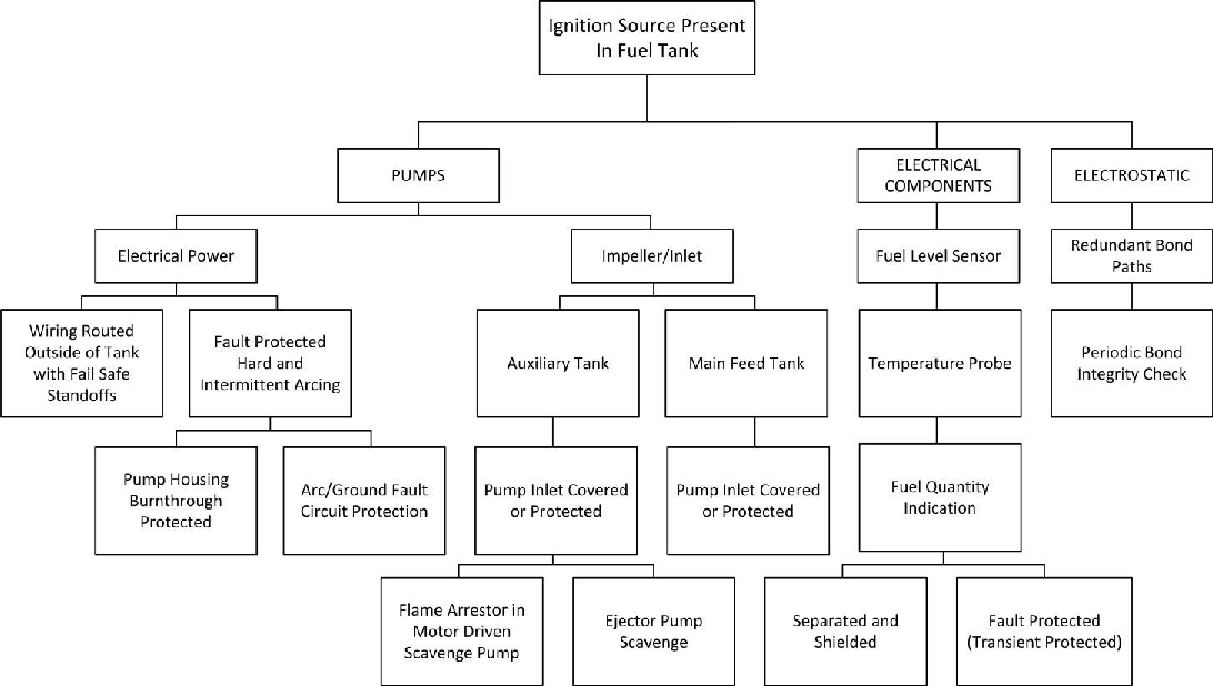
5.2.2 In the case of the installation of a flame arrestor in the inlet line to a fuel pump, the compliance demonstration for the fuel pump may be limited to showing that the arrestor was effective at precluding propagation of the flame from the pump back down the inlet line into the tank, and showing that any anticipated failures or events could not violate the explosion-proof features of the pump assembly. A CDCCL may be necessary to maintain the flame arrestor design feature. If the flame arrestor cannot be shown to be effective for the life of the installation, an Airworthiness Limitation limiting the life of the flame arrestor would be necessary. In addition, revalidation of the fuel system with other regulations (e.g. icing and reduced flow due to contamination) would be required if modifications were incorporated into the fuel feed system. The SSA criteria, process, analysis methods, validation, and documentation should be consistent with the guidance material provided in SAE ARP4761, using the unique guidance specific to the fuel tank system as defined in this AMC.
5.3 Assumptions and considerations for fuel tank system analysis
The applicant should conduct the fuel tank system analysis based on the following assumptions:
5.3.1 Fuel tank flammability
The analysis should assume that the environment inside the fuel tank is always flammable. The conditions required to ignite fuel vapour from ignition sources vary with the pressures and temperatures within the fuel tank and can be affected by sloshing or spraying of fuel in the tank. Due to the difficulty in predicting fuel tank flammability, it should be assumed that a flammable fuel/air mixture exists in aeroplane fuel tanks and it is required that no ignition sources be present. The SSA should be prepared considering all the in-flight, ground, service, and maintenance conditions for the aeroplane, assuming that an explosive fuel/air mixture is present in the vapour space of fuel tanks and vent systems at all times, unless the fuel tank has features that mitigate the effects of tank ignition (e.g. polyurethane foam).
5.3.2 Failure condition classification
Unless design features are incorporated that mitigate the hazards resulting from a fuel tank ignition event (e.g. polyurethane foam, an adequate structural margin), the SSA should assume that the presence of an ignition source is a catastrophic failure condition.
5.3.3 Latent failures
5.3.3.1 In order to eliminate any ambiguity as to the restrictions on latent failures, CS 25.981(a)(3) explicitly requires that any anticipated latent failure condition must not leave the aeroplane one failure away from a catastrophic fuel tank ignition. In addition to this limitation on latency, CS 25.1309(c) limits the latent failure conditions to those that do not create an ‘unsafe system operating condition.’ Consequently, if a latent failure condition is not extremely remote (i.e., it is anticipated to occur) and it creates an ‘unsafe system operating condition,’ then flight crew alerting must be provided to ‘enable them to take appropriate corrective action.’ Notwithstanding these restrictions on latency, there are practical limitations on the available means of compliance. For example, detecting a failure condition requires a finite period of time, and there are not always ‘appropriate corrective actions’ that can be taken during the flight. Consequently, for the purpose of complying with CS 25.981(a)(3), the period of latency for any anticipated significant latent failure condition should be minimised and not allowed to exceed one flight cycle. For the purpose of complying with CS 25.1309(c), whenever the aeroplane is operating one failure away from a catastrophic fuel tank ignition, this should be considered an ‘unsafe system operating condition,’ recognising that sometimes the only appropriate corrective action when problem detection is available is to continue to the destination but not to initiate another flight without making appropriate repairs.
5.3.3.2 Another practical limitation on the available means of compliance is the technological feasibility of providing inherent failure detection within the design for all significant failures. Sometimes periodic inspection is the only practicable means of reliably detecting a failure condition. Consequently, when such inspections are identified within the analysis as the means of detection, the inspection method and frequency must be sufficient to conclude that the probability of occurrence of the significant latent failure condition is extremely remote.
5.3.3.3 Any mandatory replacement time, inspection interval, related inspection procedure, and all the CDCCLs identified as required to prevent development of ignition sources within the fuel tank system for CS 25.981(a) must be identified in the Airworthiness Limitations Section of the ICA as fuel system Airworthiness Limitations. The Airworthiness Limitations Section should include the following:
5.3.3.3.1 A designation of the maintenance actions and alterations that must be inspected (critical inspections), including at least those that could result in a failure, malfunction, or defect endangering the safe operation of the aircraft, if not performed properly or if improper parts or materials are used.
Note: A validation inspection should be conducted to reaffirm all or a portion of the initial inspection requirements for those critical inspections that, if not performed properly or if improper parts or materials are used, could result in a failure, malfunction, or defect endangering the safe operation of the aeroplane. For those air carriers that use a mechanic for the initial inspection, an inspector should be used to conduct the validation inspection. For those air carriers that use an inspector for the initial inspection, another qualified inspector should be used to conduct the validation inspection.
5.3.3.3.2 The procedures, standards, and limits necessary for critical inspections and acceptance or rejection of the items required to be inspected, and for periodic inspections and calibration of precision tools, measuring devices, and test equipment.
5.3.4 Failure conditions
In accordance with CS 25.981(a)(3), the analysis must consider the effects of manufacturing variability, ageing, wear, corrosion, and likely damage. For the purpose of compliance with CS 5.981, ‘extremely remote’ failure conditions and ‘extremely improbable’ failure conditions are defined in AMC 25.1309. Likely damage is damage that, using engineering judgment or past experience, would lead one to conclude that an occurrence is foreseeable. Examples of likely damage are:
— a wire bundle located where a mechanic could use it as a handhold;
— an instrument located where, if someone dropped a wrench, damage would result; or
— a fuel probe located where a mechanic could use it as a step in the tank.
5.3.4.1 The analysis should be conducted considering the deficiencies and anomalies listed in paragraph 2.3 of this AMC, the failure modes identified by the review of service information (including review of supplier service data), and any other failure modes identified by the functional hazard assessment of the fuel tank system. For example, the applicant should assume the presence of conductive debris such as lockwire, steel wool, nuts, bolts, rivets, etc. CS 25.981 requires that the effects of manufacturing variability, ageing, wear, corrosion, and likely damage must be considered when showing compliance, which is needed to show compliance with CS 25.901(c). Credit for fail-safe features must be substantiated.
5.3.4.2 The level of manufacturing variability, ageing, wear, corrosion, and likely damage that must be considered should be determined based upon an evaluation of the detectability of degraded or out‑of‑specification configurations, and established and documented within the analysis. In‑service and production functional tests, component acceptance tests, and maintenance checks may be used to substantiate the degree to which these states must be considered. For example, inspection of fuel tank system bonding on production aeroplanes has shown that some bonds were inadequate. Functional testing of all bonding was incorporated to address this deficiency. In some cases (e.g. component bonding or ground paths), a degraded state will not be detectable without periodic functional tests of the feature. For these features, inspection/test intervals should be established based on previous service experience of equipment installed in the same environment. If previous experience on similar or identical components is not available, conservative initial inspection/test intervals should be established until design maturity can be assured.
5.3.5 External environment
The severity of the external environmental conditions that should be considered when showing compliance with CS 25.981 is that of the conditions established by the certification specifications.
5.3.6 External sources of tank auto-ignition
The possibility of fuel tank ignition due to surface-ignition sources created by external tank heating should be considered. This includes heating of the tank due to the operation or failure of systems outside the tank within both the pressurised and unpressurised areas of the aeroplane, such as overloaded electric motors or transformers, failures in the pneumatic system, and/or ducting that could cause localised heating of tank surfaces. In addition, the possibility of localised heating due to external fires should be considered.
5.3.6.1 CS 25.967(e) requires that, ‘Each fuel tank must be isolated from personnel compartments by a fumeproof and fuelproof enclosure.’
5.3.6.1.1 Leakage of fuel or vapour into spaces adjacent to the fuel tank, where a secondary fuelproof and fumeproof barrier is not provided, has typically been assumed for areas such as:
— The wing leading edges (including any adjacent compartment such as the strut) and trailing edges,
— Fairings located below the fuel tanks,
— Fuel pump enclosures, and
— Unpressurised areas of the fuselage surrounding fuel tanks located in the empennage.
5.3.6.1.2 Components located in these areas have been required to meet the explosion-proof requirements. These components or systems should be included in the analysis. Examples of such equipment include, but are not limited to, environmental control system (ECS) air conditioning packs, motors, power assisted valves, fuel pumps, hydraulic pumps/motors, certain flight control actuators, ECS controls, and wiring and valves.
5.3.6.2 A safety review of the flammable fluid leakage zones adjacent to fuel tanks should be conducted to determine whether the design complies with the requirements of CS 25.863(a) and CS 25.981. In general, the fire protection philosophy for any area considered a flammable fluid leakage zone is to assume that flammable vapour may be present in the zone and to minimise the probability of ignition of the vapour (CS 25.863(a)). This has typically been accomplished by using combinations of the following design considerations:
— Grounding and bonding of electrical equipment,
— Qualification of electrical equipment as explosion proof,
— Sealing of electrical connectors,
— Proper support, protection, and separation of wiring,
— Drainage provisions in the leakage zone,
— Ventilation of the leakage zone in flight and of areas around the auxiliary tanks, and
— Immediate maintenance action to correct leaks in these areas.
5.3.6.3 Surface temperatures in areas adjacent to fuel tanks
While EASA (and previously the JAA (Joint Aviation Authorities)) has accepted the use of maximum acceptable surface temperatures 27.8 °C (50 °F) below the applicable auto-ignition temperature of the fuel-air mixture (i.e. a surface temperature of 204 °C (400° F) for fuel tanks filled with kerosene), some higher temperatures have been accepted in certain cases if adequately substantiated by the applicant. Some manufacturers have substantiated that the conditions (ambient pressure, dwell time, fuel type, etc.) within certain flammable fluid leakage zones are such that a higher value may be used.
For example, maximum allowable pneumatic bleed duct surface temperatures of 232°C (450°F), with a transient excursion up to 260°C (500°F) for a maximum of two minutes, have been approved. The excursion above 232°C (450°F) occurs only during failure conditions such as an engine pneumatic high stage bleed valve failure or duct rupture. The approval of these elevated temperatures has been based on compensating design features such as a cockpit indication of over-temperature combined with associated procedures to shutoff the overheated system, insulated ducts, zone ventilation airflow which produces a lean fuel-air mixture, and an automatic over-temperature shutoff of the pneumatic system so that the temperature cannot exceed the accepted 232°C (450°F) temperature for more than two minutes. The internal tank surface temperatures resulting from the failure should not exceed the surface temperature limit for the fuel type used, as described in paragraph 3.5 of this AMC.
5.3.7 Electrical ignition sources
The applicant should perform a failure analysis of all the fuel systems and subsystems that have wiring routed into fuel tanks. Systems that should be considered include those for fuel pump power and control and indication, fuel quantity indication, fuel temperature indication, fuel level sensors, and any other wiring routed into or adjacent to fuel tanks. The analysis should consider system level failures, failures within LRUs, and the component level failures discussed below. The analysis should include the existence of latent failures and subsequent failures that may lead to an ignition source within the fuel tank. Examples include undetected failures of tank components or wiring, the undetected presence of conductive debris, damage to FQIS or level sensor probes, or corrosion, in combination with external failures such as hot shorts or electromagnetic effects. In addition, the applicant should provide a description of the protective means employed in the fuel system wiring. This should include a description of features such as separation/segregation, transient suppression devices, shielding of wiring, and methods employed to maintain configuration control of critical wiring throughout the life of the aeroplane.
5.3.8 Electrical short-circuits
5.3.8.1 One method that may provide protection of circuits that enter fuel tanks is the incorporation of a transient suppression device (TSD) in the circuit close to the point where those wires enter the fuel tanks. Consideration should also be given to protection of the wiring between the TSDs and the tank if the protection devices are not located at the tank entrance, and also to the possibility of transients being induced in the wiring between the TSDs and the electrical devices in the fuel tanks. Caution should be exercised when using a TSD to ensure that the TSD addresses both voltage and current suppression in order to limit the energy and current below the limits provided in Section 3.2 of this AMC.
5.3.8.2 Another method of protection that has been used to provide a fail-safe design with respect to electrical shorts is the separation of the wiring to electrical devices in the fuel tanks from other electrical power wires and circuits, combined with shielding between the wiring that enters the fuel tanks and any other electrical power-carrying wires in the aircraft installation. The effects of electrical short circuits, including hot shorts, on the equipment and wiring that enters the fuel tanks should be considered, particularly for the FQIS wiring, fuel level sensors, and probes. Latent failures from factors such as contamination, damage/pinching of wires during installation, or corrosion on the probes, connectors, or wiring should be considered when evaluating the effects of short circuits. The wire routing, shielding, and segregation outside the fuel tanks, including within the FQIS components (e.g., gauging units), should also be considered when evaluating the effects of short circuits. The evaluation should consider both the electrical arcing and localised heating that may result from short circuits on equipment, FQIS probes, and wiring. The evaluation of electrical short circuits should include consideration of shorts within electrical equipment, and the wiring from the equipment into the fuel tank. Prevention of fuel ignition from electrical shorts to the wiring that enters the fuel tanks may require specific wire and circuit separation and wire bundle shielding.
5.3.9 LRU design evaluation
The design review should include an evaluation of the separation and protective features incorporated into any fuel system LRU whose failure could result in high‑level electrical power (i.e., above the intrinsically safe levels) entering the fuel tank. For example, circuit board failures could cause the LRU power supply circuits for the fuel quantity gauging system to come into contact with the circuits that lead into the fuel tank, resulting in a possible ignition source. Failures that can lead to violating the separation features within the LRU can be external or internal events. External failures include overvoltage or overcurrent, high humidity, temperature, vibration, shock, and contamination. Internal failures include manufacturing defects or flaws in the conductor, substrate, or coating. To address these failures, the design should either provide isolation and physical separation between the critical circuits, such as the circuits that enter a fuel tank, or adequate protective features, such as the transient suppression devices as discussed earlier, to protect the circuits that enter the fuel tank. Any LRU that meets the design requirements identified in Underwriters Laboratories Inc., UL 913, Intrinsically Safe Apparatus and Associated Apparatus for use in Class I, II, III, Division 1, Hazardous (Classified) Locations, is considered acceptable, provided the following issues are addressed:
— Ideally, higher power circuits within the LRU should not be located on the same circuit board or in a wire harness or electrical connector with intrinsically safe circuits or wiring;
— There should be a physical barrier between circuit boards to isolate the intrinsically safe circuits from the effects of broken components or fire within the LRU; and
— If limiting devices are installed on the same circuit board in series with the system circuitry to limit the amount of power or current transmitted to the fuel tank, there should be 7.62 cm (3 inches) between the traces, unless the manufacturer can justify a smaller separation on the basis that the effects of fire on the circuit board will not compromise the intrinsically safe circuit(s).
5.3.10 Electromagnetic effects including HIRF
See AMC 25.954 for guidelines on establishing compliance with the requirements for fuel system protection from lightning effects.
5.3.10.1 The evaluation should consider the electromagnetic effects due to HIRF, electrical transients, and RF emissions on the fuel system conductors (e.g. fuel tank plumbing, structure, fuel, equipment and wiring) within the fuel tanks, particularly for the FQIS wiring and probes. The applicant should also consider the latent failures from factors such as contamination, damage, or corrosion on the probes or wiring when evaluating the effects of electrical transients. The wire routing, shielding, and segregation of conductors (e.g., plumbing, component casings, wiring, etc.) outside the fuel tanks should also be considered when evaluating the effects of electrical transients because the generation of the transient and the coupling to conductors may occur outside the fuel tanks. The evaluation should consider both electrical sparks and arcs, and localised heating, which may result from electromagnetic effects on the fuel tank system, FQIS probes, and wiring.
5.3.10.2 The evaluation should consider latent failures of electromagnetic protection features, such as shielding termination corrosion, shield damage, and transient limiting device failures, and the applicant should establish appropriate indications or inspection intervals to prevent the existence of latent failure conditions. The failure of other system components may also affect the protection against electromagnetic effects. Consequently, the evaluation should consider the effect of any anticipated failure on the continued environmental protection.
5.3.10.3 The evaluation of electromagnetic effects should be based on the specific electromagnetic environment of a particular aeroplane model. Standardised tests, such as those in EUROCAE ED-14G Change 1 dated January 2015, ‘Environmental Conditions and Test Procedures for Airborne Equipment’, and the equivalent RTCA, Inc., Document No DO-160G dated December 2010, Sections 19 and 20, are not sufficient alone to show that the appropriate standardised test categories, procedures, and test levels of EUROCAE ED-14G/RTCA DO-160G are selected, without an evaluation of the characteristics of the specific electromagnetic environment and the induced transient levels assigned to systems installed within a particular aeroplane model. Simulation of various latent failures of fuel system components within the tanks may be needed to show the effectiveness of the transient protection. The effectiveness of these features should be verified using the appropriate test procedures and test levels of EUROCAE ED-14G/RTCA DO‑160G, determined above.
5.3.10.4 Prevention of fuel ignition due to electromagnetic effects may require specific wire segregation and separation, wire bundle shielding, or transient suppression for wires entering fuel tanks. The effectiveness of the transient protection features should be verified using the appropriate test procedures and test levels of EUROCAE ED-14G/RTCA DO-160G, determined above.
5.3.10.5 Redundancy of bond paths
A failure of bonding jumpers is generally considered a latent failure, since there is no annunciation or indication of the bonding failure. The aeroplane fleet fuel tank inspections that occurred as a result of the TWA 800 investigation (National Transportation Safety Board Aircraft Accident Report NTSB/AAR‑00/03, ‘In-flight Breakup Over the Atlantic Ocean Trans World Airlines Flight 800, Boeing 747-131, N93119, Near East Moriches, New York,’ dated July 17, 1996) showed that failures of bonding jumpers, due to damage, wear, or manufacturing errors, were not unusual. Based on this, it would be difficult to show that the probability of a failure of a single bonding jumper is extremely remote or extremely improbable. Therefore, electrical bonding jumpers or other bonding provisions would need to consider the consequences of these latent failures. This may result in designs that incorporate electrical bonding redundancy, if the failure of a single electrical bonding feature could create a fuel tank ignition source. Additionally, manufacturers would need to consider the use of appropriate maintenance to detect failed bonding jumpers. An example of such maintenance might include periodic inspections to limit latency.
5.3.10.6 Self-bonding couplers
Early generation, self-bonding, flexible fuel couplers did not have multiple bonding paths. Thus, these bonding couplers exhibited single-point failures that caused a loss of function. These self-bonding flexible couplers failed because of missing bonding springs, anodising on bonding surfaces, and incorrect installation. The safety assessment of designs incorporating multiple bonding paths must consider these failure modes, and qualification testing should show that no ignition sources are present in the full-up (non‑degraded condition) and possible degraded condition with failure modes present within the couplings. For example, failure assessments of clamshell-type, self‑bonding metallic couplings in composite fuel tanks have shown that arcing could occur if a coupling was improperly latched, or became unlatched and fell to the bottom of the fuel tank. The design of the coupling would need to address these failure modes. Improper latching could be addressed through positive latching features with tactile and visual indications that the coupling is properly latched. Redundant fail-safe features, such as redundant hinge and latching features, redundant bonding features, etc., may be needed to address other possible failure modes.
5.3.10.7 Resistance or impedance limits of aeroplane electrical bonding provisions
5.3.10.7.1 There is no specific EASA guidance on the maximum resistance or impedance of aeroplane electrical bonding provisions because electrical bonding within a fuel system should be tailored to the performance requirements of a particular aeroplane design. The electrical bonding should consider the electrical sources, electrical faults, and electrostatic charges. The electrical bonding should also consider the fuel system design of the specific aeroplane, which would include the structure material used (aluminium, carbon-fibre composites, fibreglass composites, etc.), the configuration of the fuel system (routing of fuel tubes, wires, and hydraulic tubes), and the electrical bonding concept (intentional isolation, self-bonding fittings, separate bonding jumpers, etc.). Given the large variation in design approaches and the close relationship between the design approach and the electrical bonding requirements, it is not practical for EASA to provide specific guidance on the maximum bonding resistance or impedance.
5.3.10.7.2 Some type certificate (TC) holders have performed tests on their aeroplanes to determine the specific requirements for electrical bonding. Others, in the absence of specific aeroplane test data, have chosen conservative electrical bonding approaches. The approach is a decision each TC holder should make based on the specific situation for that TC holder’s aeroplane models.
5.3.10.8 Bonding integrity checks
Past experience has shown that measurement of bond resistance is the desired method of ensuring bond path integrity. During bonding resistance measurements, the protective finish of components might be damaged in order to penetrate the insulating anodised surface layer, which may lead to subsequent corrosion damage. This concern has resulted in some TC holders defining non-intrusive inspections for electrical bonding. These inspections may include detailed visual inspections provided that the quality of the electrical bonding feature can be adequately assessed by visual cues, such as visible corrosion, breakage, tightness, or missing bonding provisions. For critical bonds, this method would not by itself be adequate. Other inspection methods include inductively coupled loop resistance measurements that eliminate the need to disconnect bonding jumpers, or to penetrate corrosion‑prevention coatings. The need for bonding inspections, the frequency of the inspections, and the determination as to whether the inspections must be an Airworthiness Limitation should be established under the fuel tank SSA.
5.3.10.9 Bond corrosion and integrity
5.3.10.9.1 Degradation of electrical bonding provisions, such as bonding jumpers, has occurred on in‑service aeroplanes. Results from aeroplane fuel tank inspections conducted on a sample of aeroplanes by manufacturers and operators showed discolouration, corrosion, and damage to bonding jumpers. It is not clear whether the discolouration indicates that corrosion that will become more severe with time, or whether it is simply a surface colour change. The applicant should define the bonding feature characteristics — such as visible corrosion, discolouration, jumper strand separation, and jumper strand breakage — that will be used to distinguish discrepant bonding provisions.
5.3.10.9.2 The level of corrosion observed on bonding features, specifically on bonding jumpers, varies greatly across aeroplane fleets. While some aeroplanes within a fleet and certain locations within the fuel tanks showed no evidence of corrosion, other aeroplanes and locations exhibited higher levels of corrosion. Inspection results indicate that the materials used in certain bonding jumpers (tin-plated copper) may be more prone to corrosion. Nickel-plated copper wire does not experience similar corrosion. Corrosion programs for aeroplane structures have long recognised the variability of corrosion within the fleet. Factors that influence the level of corrosion of bonding jumpers include the fuel type (sulphur content, etc.), the presence of water in the fuel tank, installation effects such as cracking of the tin plating when the jumper is installed, the temperature, humidity, and chemicals used for preparation of the fuel tanks prior to aeroplane storage, etc. While certain levels of corrosion or discolouration may be acceptable between inspection intervals, the showing of compliance should include substantiation that the materials used in the bonding jumpers are appropriate for use in the fuel tanks in consideration of the proposed inspection intervals. This substantiation should consider the variability in corrosive environments and the factors noted above that may exist on in‑service and stored aeroplanes in the fleet.
5.3.10.10 CS 25.981 states: ‘(a) No ignition source may be present at each point in the fuel tank or fuel tank system where catastrophic failure could occur due to ignition of fuel or vapours.’ Fuel tube flexible couplings and components as small as nuts, bolts, and washers may develop sufficient charge to cause arcing due to electrostatic conditions if not properly accounted for in the design. Electrical bonding would need to be considered if these couplings are identified as ignition sources during the ignition source evaluation and assessment.
5.3.11 Friction sparks
The failure modes and effects analysis (FMEA) should include an evaluation of the effects of debris entering the fuel pumps, including any debris that could be generated internally, such as any components upstream of the pump inlet. Industry practices for fuel tank cleanliness, and design features intended to preclude debris entering the fuel pumps, have not been effective at eliminating debris. Service experience has shown that pump inlet check valves, inducers, nuts, bolts, rivets, fasteners, sealant, lockwire, and so forth have been drawn into fuel pumps and contacted the impeller. This condition could result in the creation of friction sparks, and it should be an assumed failure condition when conducting the SSA. Fail-safe features should be incorporated into the fuel pump design to address this condition. Examples of means that may be incorporated into the fuel pump design to address this concern include:
— the installation of inlet flame arrestors,
— the use of reticulated foam,
— the use/installation of ejector fuel pumps without impellers to scavenge fuel, or
— maintaining fuel over the pump inlet throughout the aeroplane flight attitude envelope.
6 COMPONENT
FAILURE MODE CONSIDERATIONS
6.1 Component qualification review
The qualification of components, such as fuel pumps, has not always accounted for unforeseen failures, wear, or inappropriate overhaul or maintenance. Failures to account for these failure modes and testing the pump using the procedures defined in Military Standard MIL-STD-810H, Method 511.6, Explosive Atmosphere, have led to some fuel pumps entering airline service having never been tested to demonstrate whether they have explosion-proof capabilities. This combined experience suggests that more needs to be done to establish the capabilities of fuel pumps and other fuel system components to operate safely in an explosive environment. Such a capability should be substantiated considering these factors in addition to the conditions noted in paragraph 3.3 of this AMC. The amount of qualification review can be significantly reduced if the fail-safe features noted earlier in this AMC are followed (e.g. not operating pumps in the vapour spaces of the tank, incorporating arc fault or ground fault protection on the electrical circuit, etc.). Therefore, an extensive evaluation of the qualification of components may be required if a qualitative assessment of the component and installation features does not eliminate the component as a potential ignition source.
6.2 Maximum component temperature for qualification of fuel system components
The maximum component temperatures may be determined experimentally. Tests should be conducted that are long enough for the component to reach the maximum temperature. All the foreseeable failures and malfunctions of the fuel tank components (including those failures and malfunctions that could be undetected by the flight crew and maintenance personnel) should be considered when determining the maximum temperatures.
6.2.1 Components mounted adjacent to the exterior surface of the fuel tank can create a high localised temperature on the inner surface of the tank. This can be investigated by laboratory tests that duplicate the installation, or by a validated heat transfer analysis using the maximum potential temperature of the component.
6.2.2 When aeroplane equipment or system components such as engine bleed air ducting or ECS are located near fuel tanks, an FMEA should be performed to determine the failures of adjacent systems or components that could cause elevated surface temperatures. The maximum internal tank temperatures that can occur during normal and failure conditions should be determined. Systems, such as over-temperature protection devices, should be evaluated to determine whether periodic health checks are necessary to ensure that latent failures do not exist.
6.3 Possible failure modes for determination of maximum component temperatures
The following list identifies some possible failure modes, but not all the conditions, that should be explored in determining the maximum temperature expected for fuel tank components:
6.3.1 Fuel pumps
6.3.1.1 Normal fuel pump operation considering the highest hot day ambient and fuel tank temperatures: in many cases, fuel pump motors are protected by a (single) three-phase thermal circuit breaker. In several instances, the resetting of circuit breakers has resulted in arcing inside the fuel tank and the development of an ignition source from an existing failure. Therefore, the fuel pump circuit should also preclude the development of an ignition source if the breaker is reset or forced in by a mechanic. Methods that may be used to address this foreseeable failure condition include the use of circuit-protective features such as non-resettable, fast-acting AFCB or GFI circuit breakers.
6.3.1.2 Two-phase operation of three-phase electrical fuel pumps: a failure of a single phase of a multiple-phase fuel pump will significantly increase the load on the remaining phases of the pump and the generation of heat in the pump. In many cases, thermal protection features within the pump have been incorporated to address this failure condition, but these means have not been effective at preventing continued operation of a pump with a failed electrical phase. Another failure condition that should be considered is the subsequent failure of a second phase of the pump and possible arcing or heat damage. In general, pumps should not be allowed to operate following a failure of a single electrical phase of the pump if such operation could result in the development of an ignition source. Automatic protective means, such as AFCBs or GFIs or other means, should be provided to shut down the pump when a single electrical phase failure occurs. Periodic inspections or maintenance of these features may be required.
6.3.1.3 Dry operation of fuel pumps, including lack of lubrication: service history has shown that flight crews and maintenance personnel have inadvertently operated fuel pumps for long periods of time without fuel in the fuel tank. Fuel pumps are typically qualified for dry run operation for periods of time based upon assumptions made about the possible duration of inadvertent operation, or the failure conditions, which could result in dry running of the pump. For example, some pumps were operated during qualification testing up to a maximum of 8 hours continuously, with total accumulated dry run operation of 24 hours. These qualification tests were accomplished in order to show that the fuel pump performance was still adequate following the dry pump operation. The tests were not conducted in an explosive environment and, hence, were not intended to qualify the pumps for such operation. In other cases, previous approvals were predicated on the assumption that the fuel pump would not be dry run operated because the pump would be turned off by the flight/ground crew following a pump low‑pressure indication. Extended dry operation of pumps may result in surface temperatures above the auto-ignition temperature of the fuel, or may expose the pump to dry run operation where debris from the fuel tank could enter the impeller and cause sparks. Manufacturers’ recommended procedures have not been shown to be adequate in preventing dry run operation. Therefore, additional fail-safe features are necessary to preclude ignition sources caused by the dry run operation of aeroplane fuel pumps. One or more of the following fail-safe means should be considered for the protection of fuel pumps:
1. Incorporating design features to keep the fuel pump inlet submerged in jet fuel to prevent dry running of the pump under all operating conditions.
2. Incorporating automatic pump shutoff features into the fuel pump or aeroplane to preclude dry run operation.
3. Other means such as the installation of flame arrestors in the fuel pump inlet to preclude flame propagation into the fuel tank.
6.3.1.4 The temperatures associated with the fuel pump following wet operation with wet mechanical components both at zero and reduced fluid flow.
6.3.1.5 The temperatures associated with moving mechanisms that are locked or seized.
6.3.1.6 The temperatures generated as a consequence of pump impeller slippage.
6.3.1.7 High temperatures or high currents due to a broken shaft. The design has to contain the broken shaft, and the pump and its control system must consider the high currents and temperatures that would follow.
6.3.1.8 Failed bearings: the effects of wear on the fuel pump features incorporated into the design to maintain explosion-proof characteristics should be evaluated. For example, the wear of bearings or failures, including spinning of any bushings, and the possible effects on quenching orifices should be evaluated. In many cases, the fuel pump explosion-proof features are not redundant, and the failure or degradation of the features is latent. If single or probable combinations of failures in the fuel pump can cause an ignition source, CS 25.981 requires the incorporation of the fail-safe features noted previously. If wear of the pump can cause the degradation of fail-safe features, appropriate inspections, overhaul, or life limiting of the pump should be included in the Airworthiness Limitations Section of the ICA, per CS 25.981(d) and Appendix H to CS-25, paragraph H25.4.
6.3.2 FQIS
6.3.2.1 FQIS wiring in the tank, with maximum voltage and current applied, considering normal and failure conditions, including the effects of high‑voltage systems outside the tank in proximity to the FQIS wires.
6.3.2.2 FQIS components in the normal and failed state with the above associated maximum voltages and fault currents applied.
6.3.3 Float switch system
Float switch system temperatures should be determined considering the maximum environment temperatures and the application of the applicable maximum voltage and fault currents.
6.3.4 Fuel system components
The temperatures of the fuel system components should also be evaluated considering the failure of the bonding straps.
6.3.5 Pneumatic system
Pneumatic system temperatures need to be evaluated for the effects of duct ruptures impinging on the external tank surface. Radiant and conducted heat transfer associated with the tank and components affecting tank wall temperatures should also be considered (see the previous discussion of spaces adjacent to fuel tanks).
6.3.6 Electrical defects and arcing
Electrical defects that generate excessive heat, and arcing at the electrical connections to the pump housing or within the connector.
6.3.7 Submerged heat exchangers
Submerged heat exchangers and supply tubing operating under conditions of maximum heat rejection to the fuel. This should include failures in any systems outside the fuel tank that could result in heat exchanger or supply tubing surface temperatures exceeding 204 °C (400 °F).
6.3.8 Failed or aged seals
6.3.8.1 Spraying of fuel in the tank from any pressurised fuel source may cause electrostatic charging of the components in the fuel tank. In addition, the use of sealant in connectors that is not compatible with the fuel may allow leakage into the connector and the possibility of a fire near the connector.
6.3.8.2 Fuel line couplings
Ageing of seals may result in hardening of the seal material and leakage and spraying of fuel within the fuel tank; therefore, fuel line coupling designs should be evaluated and a design life should be established for all seals that are shown to age and allow leakage that can cause unacceptable electrostatic charging of components.
6.3.9 Fuel pump cooling flow
Fuel used for the cooling of fuel pumps may be sprayed from the fuel pump. Fuel pump cooling flow should not be sprayed into the fuel tank vapour space for the same reason as stated in 6.3.8 for the spraying of fuel. Means should be provided to distribute the discharged cooling fuel into the fuel tank at or near the bottom of the fuel tank.
6.3.10 Explosion-proof electrical connector sealant and seals
Electrical connections to fuel pumps are typically located either inside or outside the fuel tank in areas of the aeroplane where the presence of flammable fuel vapour should be assumed because no secondary sealing of fuel is provided. Fuel leakage and corrosion at electrical connectors located outside the fuel tank has allowed the presence of both flammable vapour and electrical arcing at connectors, resulting in fires. In other applications, arcing has occurred at the pump connections inside the fuel tanks, requiring the installation of appropriately sized steel shields to prevent arcing through the connector or pump housing into the fuel tank or areas where flammable vapour could exist.
6.3.11 Arcing at the pump electrical connections
Wear, corrosion, manufacturing variability (e.g. tolerances), connector distortion and seal damage from ice, and bent pins in the connector are examples of failures that have caused high resistance or shorting and arcing in electrical connectors. Based upon historical data showing that these and other failure modes listed previously in this AMC have occurred in fuel pump connectors, arcing in the connectors is a foreseeable failure. Each of these single or cascading failure modes should be included in the FMEA. The high current loads present during pump start‑up and operation exacerbate arcing in the connector. The size and duration of the arcing event should be established based upon the fuel pump electrical circuit protection features. Arcing at the pump electrical connections, and the resultant damage to the pump connector, housing, and explosion-proof features due to intermittent, and maximum energy, arcing events should be assumed. If fuel is present on the backside of the connector, failures resulting in fuel leakage in conjunction with arcing in the connector should be assumed if the fuel leak is a latent failure or is the result of a cascading failure. The design of traditional fuel pumps has resulted in the need to install AFCB or GFI protection features to address foreseeable failures and limit the energy release during an arcing event to prevent an ignition source from occurring. The pump connector should be shown to contain any resultant arcing or fire and to maintain all surface temperatures below the auto-ignition temperature of the fuel. Component manufacturer maintenance records and qualification test results should be reviewed as part of the safety analysis process to establish that any sealants and materials in the connector are compatible with the operating environment and to determine whether a design life or periodic inspections for the pump connector are needed.
7 AIRWORTHINESS
LIMITATIONS FOR THE FUEL TANK SYSTEM
7.1 CS-25 Appendix H, paragraph H25.4(a)(2) requires that each mandatory replacement time, inspection interval, related inspection procedure, and all the CDCCLs approved under CS 25.981 for the fuel tank system, be included in the Airworthiness Limitations Section of the ICA.
7.2 Critical design configuration control limitations include any information necessary to maintain those design features that were defined in the original type design as being needed to preclude the development of ignition sources. This information is essential to ensure that maintenance, repairs, or alterations do not unintentionally violate the integrity of the original fuel tank system type design. The original design approval holder should define a method to ensure that this essential information will be evident to those that may perform and approve repairs and alterations. Visual means to alert the maintenance crew should be placed in areas of the aeroplane where inappropriate actions may degrade the integrity of the design configuration. In addition, this information should be communicated by statements in the appropriate manuals, such as wiring diagram manuals.
7.2.1 CDCCLs may include any maintenance procedure that could result in a failure, malfunction, or defect endangering the safe operation of the aeroplane, if not performed properly or if improper parts or materials are used. This information is essential to ensure that maintenance, repairs, or alterations do not unintentionally violate the integrity of the original type design of the fuel tank system.
7.2.2 CDCCLs are intended to identify only the critical features of a design that must be maintained. CDCCLs have no intervals; they establish configuration limitations to maintain and to protect the ‘critical design features’ identified in the CDCCLs. CDCCLs can also include requirements to install placards on the aeroplane with information about the critical features. For example, certain components of a fuel pump (or all the components) may include critical features that are identified as CDCCLs. These critical features must be identified in the Airworthiness Limitations Section of the ICA and should also be identified in the component maintenance manual (CMM) as CDCCLs to provide awareness to maintenance and repair facilities.
7.2.3 Certain CDCCLs apply to elements of fuel system components. As such, maintenance of those critical features may be covered in a CMM. When Airworthiness Limitations need to call out aspects of CMMs, it is a best practice to limit the CDCCL-controlled content to only those maintenance tasks directly impacting a CDCCL feature, rather than requiring the complete CMM to be a CDCCL.
7.3 Any fuel tank system components that are determined to require periodic maintenance, inspection, or overhaul to maintain the integrity of the system or maintain protective features incorporated to preclude a catastrophic fuel tank ignition event must be defined and included in the Airworthiness Limitations Section of the ICA. An inspection Airworthiness Limitation has a specific task and interval (such as 10 years). The inspection interval should be established based on the standard practices defined in AMC 25.1309 for the evaluation of component failures. The inspection could also be required following maintenance to verify that a CDCCL feature is maintained. Examples of inspection Airworthiness Limitations include the following:
7.3.1 Ageing fuel line coupling seals/o-rings
In certain instances, the materials used in fuel line couplings may lose flexibility and harden with age. Under pressurised operation, the seal may allow fuel leakage. This will allow spraying of fuel in the tanks or other areas of the aeroplane where spraying fuel could create a fire hazard. Repetitive inspections, functional checks, or mandatory replacement intervals may be required to prevent leakage.
Note: While not related to compliance with CS 25.981, the hazards associated with the ageing of fuel coupling O-rings, resulting in air entering fuel lines during suction feed operation, should also be addressed when developing the fuel system maintenance program.
7.3.2 Wear of pump bushings, bearings, and seals
Wearing of pump bushings, bearings, and seals may significantly affect the performance of fuel pumps and degrade the features necessary to maintain the explosive-proof qualification. In most cases, these failure conditions are latent; therefore, incorporation of other fail-safe features, as discussed earlier in this AMC, should be considered. If fail-safe features, such as the installation of feeder tanks that are filled using ejector pumps, are incorporated, the functioning of those features would need to be ensured by indications or periodic functional tests. The installation of fuel level sensors in the feeder tanks would provide continuous monitoring of the function. Another means could be the installation of flow indicators in the flow line of the ejector pump that can be viewed by maintenance personnel, and a mandatory periodic inspection of this function is one example of a method of a mandatory maintenance action.
7.3.3 Fuel pump electrical power protective features
If a failure of an AFCB or GFI protective feature and/or a thermal fuse (closed) is latent and this feature is needed to maintain the fail-safe features, periodic checks would likely be needed. The inspection interval, and the need for built-in test features with indications of failures, should be established through the safety analysis process and should consider the factors described in paragraph A.3.4.3 of Appendix A to this AMC.
7.3.4 Transient suppression/energy limiting devices
If a failure of the device is latent and this feature is needed to maintain the fail-safe features, periodic checks will likely be needed.
7.3.5 Wire shield grounding
Component grounds and wires will likely require inspections and measurements to determine whether they are properly grounded.
7.3.6 Fuel tank access panel/door seals
Maintenance tasks should adequately provide procedures for inspections and checks of access panels and door seals.
7.3.7 Corrosion, wear, and damage to fuel pump connectors
Maintenance tasks should provide adequate procedures for inspecting and checking fuel pump connectors for wear, corrosion, and damage.
7.3.8 Integrity of the fuel pump electrical supply conduit
Maintenance tasks should provide adequate procedures for inspecting the integrity of the structure, sealing, drain holes, and bends of the electrical supply conduit to the fuel pump.
7.4 Maintainability of design and procedures
Maintainability, both in the design and procedures (i.e. the master minimum equipment list, aeroplane maintenance manual, etc.), should be verified by the applicant. This should include, as a minimum, verification that the system and procedures support the safety analysis assumptions and are tolerant to the anticipated human errors.
7.5 Incorporation by reference into Airworthiness Limitations
7.5.1 Where the words ‘in accordance with’ or ‘per’ are used in the Airworthiness Limitations, the procedures in the referenced document must be followed to ensure that the critical design feature is maintained. Any changes to these procedures require approval by EASA before they can be used.
7.5.2 Where the words ‘refer to’ are used in the Airworthiness Limitations, the procedures in the referenced document represent one method of complying with the Airworthiness Limitation. An accepted alternative procedure may be developed by the operator in accordance with its procedures in its maintenance program/manual. Prior approval by EASA is not required for this action.
7.6 Visible identification of CDCCLs
7.6.1 CS 25.981(d) establishes a requirement for visibly identifying the critical features of a design that are located in certain areas. The DAH should define a method of ensuring that this essential information will be communicated with statements in the appropriate manuals, such as wiring diagram manuals, so it will be evident to those who perform and approve such repairs and alterations, and it will be identified as a CDCCL.
7.6.2 An example of a CDCCL that would result in a requirement for visible means would be maintaining wire separation between the FQIS wiring and other high-power electrical circuits where the separation of the wiring was determined to be a CDCCL. Acceptable methods of providing visible means would include colour coding and labelling the wiring. For retrofits of markings onto existing wiring, the placement of identification tabs at specific intervals along the wiring would be acceptable. Standardisation within the industry of the colour coding of the wiring used for the fuel tank system would assist maintenance personnel in the functional identification of wiring. It is recommended to use pink coloured wiring as a standard for fuel tank system wiring.
Appendix
A. Certification of Arc Fault Circuit Breakers (AFCBs) or Ground Fault
Interrupters (GFIs)
A.1 PURPOSE
This Appendix provides guidelines for the certification of AFCB or GFI devices that have been shown to be practical means to protect the circuits of electric-motor fuel pumps and other fuel tank components that use higher than intrinsically safe electrical power (for example, motor‑operated valves).
A.2 BACKGROUND
A.2.1 Service experience has shown that failures in the power supply circuit of a fuel pump, discussed in the body of this AMC, can result in ignition sources and, therefore, must be assumed as a foreseeable failure condition. Traditional thermal circuit breakers are sized to prevent nuisance trips during fuel pump transient power demands and have not tripped when intermittent electrical arcs occurred. Intermittent arcing can erode metallic barriers such as conduits, electrical connectors, and the pump housing, resulting in a loss of the integrity of the explosion-proof features, or creating ignition sources outside in areas adjacent to the fuel tank. Addressing the failure modes discussed in this AMC has resulted in the need to provide fast-acting GFI or AFCBs in traditional fuel pump electrical circuits in order to show compliance with CS 25.981.
A.2.2 AFCBs have been used as a practical means to protect against arcing in the power circuits of fuel pump motors powered by either alternating current or direct current. SAE International has issued two aerospace standards for AFCBs, one for alternating current circuits and one for direct current circuits. (See paragraph B.3 of Appendix B of this AMC).
A.2.3 Fuel pump housings and metallic conduits are grounded to the airframe, and any arcing to the cavity wall or conduit creates a ground fault. Therefore, GFIs have been used in AC pump power circuits as a practical means to ensure that power is quickly disconnected from the fuel pump in the event of a ground fault in the pump or the associated power wiring.
A.3 CERTIFICATION GUIDELINES
One acceptable means for the applicant to show compliance with the applicable regulations is to demonstrate, through design, review, analysis, and test, that the AFCB or GFI performs as intended under any foreseeable operating conditions and addresses the following guidance:
A.3.1 Fault detection trip levels
A.3.1.1 The applicant should show that the AFCB or GFI can distinguish between actual fault events and events characteristic of the normal aeroplane pump start-up operating loads and environmental conditions. Laboratory testing and/or aeroplane ground/flight testing should be performed to show the ‘intended function’ of the AFCB or GFI. The test methods chosen should reproduce the most common types of arcing in fuel pumps that occur in an aeroplane environment due to ground or arc faults. The AFCB or GFI should be designed to prevent nuisance tripping due to normal aeroplane electrical loads and electrical bus switching, and to operate continuously with the normal and abnormal aeroplane electrical bus switching characteristics associated with the master minimum equipment list dispatch relief configurations.
A.3.1.2 Installation of the AFCB or GFI should not result in an appreciable increase in the loss of the fuel pump function. A reliability requirement of the order of 100 000 hours mean time between failures may be satisfactory, but the applicant should show that a failure of the AFCB or GFI does not result in an appreciable increase in the occurrence of failures that result in the loss of fuel pump function.
A.3.1.3 Sufficient laboratory testing and aeroplane testing should be conducted to show the AFCB or GFI nuisance trip performance, including tests for lightning, HIRF, and electromagnetic compatibility. In addition, sufficient laboratory testing should be conducted to show that the AFCB or GFI trips before arcing in the fuel pump can lead to the ignition of fuel vapour in the fuel tank.
A.3.1.4 A means should be provided to latch the AFCB or GFI in a state that removes power from the fuel pump motor in the event that a ground fault has been detected, until the AFCB or GFI is reset. A trip of a single AFCB or GFI should not be reset until the reason for the trip has been determined and repaired, or until it has been determined that no ground fault exists. Intermittent arcing can cause tripping of circuit protection devices resulting from failures that are difficult to isolate during maintenance actions. Single trip events may be attributed to a nuisance fault. However, maintenance instructions should include notes that state that repeated tripping of devices indicates that an intermittent fault exists, and the circuit should not be energised until the fault is isolated and repaired.
A.3.2 Software
Inadvertent operation of multiple AFCB or GFI devices has the potential to affect the continued operation of more than one engine, a condition that EASA considers to be hazardous. The software used by the AFCB or GFI devices should be developed and verified in accordance with the latest version of AMC 20-115.
A.3.3 Airborne electronic hardware
Application-specific integrated and complex circuits used by the AFCB or GFI devices should be developed and tested in accordance with the latest version of AMC 20-152.
A.3.4 System safety assessment
A.3.4.1 AFCB or GFI devices may be installed in circuits that perform essential or critical functions, and/or their performance could impact the safety of flight. The applicant should perform an installation SSA in accordance with CS 25.901(c), 25.981(a) and (d), and 25.1309. The SSA should include a functional hazard assessment to determine the effects of failures of the AFCB or GFI devices on the safety of the aeroplane and to verify that the design limits the probability of undesirable failure conditions to acceptable levels. In addition, the applicant should address the potential for possible common cause trips due to hardware/software errors and common cause trips due to environmental conditions such as HIRF (CS 25.1317), lightning (CS 25.954 and 25.1316), and electromagnetic interference (CS 25.1301, and 25.1353(a)).
A.3.4.2 A failure to provide fuel pump power due to the unintended activation of multiple AFCB or GFI devices has the potential to affect the continued operation of more than one engine. A circuit‑protective device failure, cascading failure, or common cause failure that affects multiple engines would be non-compliant with CS 25.903(b) if it prevents the continued operation of the remaining engines, or requires immediate crew action to prevent a multiple engine power loss.
A.3.4.3 A failure of an AFCB or GFI device to detect an arc or ground fault condition in a fuel pump circuit can contribute to a catastrophic failure condition. Assuming that the loss of the explosion-proof features of the pump (examples discussed in paragraph A.2.1) or arcing at the electrical connector could result from a single failure, EASA considers the undetected failure of an AFCB or GFI alone, which prevents its detection of or response to an arc or ground fault, to be a hazardous failure condition. The probability of a loss of arc or ground fault protection should either be shown to be extremely remote (if latent, consistent with the requirement of CS 25.981(a)(3)) or annunciated to the flight crew prior to flight. If failures of the AFCB or GFI can contribute to hazardous or catastrophic failure conditions, the safety assessment should analyse the common cause failures or design errors that could result in these conditions and verify that appropriate protection to prevent them is provided. Due to the nature of AFCB and GFI devices, special attention should be given to protection from lightning, EMI, and HIRF.
A.3.4.4 As discussed in Section A.3.7 below, means should be provided for the flight crew to reset the AFCB or GFI in the event that more than one fuel pump AFCB or GFI trips simultaneously in flight.
A.3.4.5 Further, the applicant should show by design, analysis, and fault insertion testing, if applicable, the validity of failure analysis assumptions, and show that the probability of the failure of AFCB or GFI to detect the existence of a ground or arc fault condition and remove power from a pump is extremely remote (10-7 or less) when combined with a single failure as assumed in Section A.3.4.3. In order to show this, AFCB and GFI installations have typically required an automatic built-in test feature that verifies the AFCB or GFI is operational before applying power to the fuel pump prior to each flight (see Section 5.3.3 of this AMC).
A.3.5 Power and ground requirements
AFCBs or GFIs are active devices and they require power to function. The applicant should show that the AFCB or GFI power and ground connections are implemented such that all the aeroplane’s load margins are sufficient and that proper circuit protection or other methods are used to protect the AFCB or GFI power and ground wiring. The applicant should also show that there are no hazards to maintenance or flight crews due to possible hot shorts to electrical panels containing AFCBs or GFIs. In addition, if the installation of AFCBs or GFIs involves the direct replacement of devices on a given electrical panel, the applicant should show that there is adequate power/heat dissipation and ensure a safe touch temperature.
A.3.6 Built-in test
AFCB and GFI devices should incorporate the built-in test and annunciation features needed to meet the reliability requirements for showing compliance with CS 25.981(a)(3). For example, if a single or cascading failure in the fuel pump electrical circuit can result in an ignition source, a circuit protection feature failure rate less than extremely remote (1 x 10⁻⁷) would be required in order to comply with CS 25.981. Traditional protective devices without built-in tests and annunciations of failures have not been shown to achieve this level of reliability. Applicants should consider installing multiple protective devices in series or providing built-in tests with annunciation.
A.3.7 Troubleshooting procedures
A.3.7.1 Because AFCBs or GFIs are capable of detecting ground paths on pumps and aeroplane wiring that may not be detected by visual inspection, the applicant should define the operational and maintenance philosophies and the methodology associated with an AFCB or GFI trip that does not rely solely on visual inspections. The applicant should show how the maintenance procedures would be able to safely distinguish and diagnose an AFCB or GFI trip and a nuisance trip without causing a fuel tank explosion. Operational instructions and maintenance procedures should be provided to prevent the resetting of tripped AFCBs or GFIs until it can be assured that resetting an AFCB or GFI will not cause the occurrence of a fuel tank explosion. Human factors should be taken into account to minimise the possibility of human errors during aeroplane operation and maintenance.
A.3.7.2 If multiple boost pumps are protected with AFCB or GFI devices such that the continued operation of multiple engines could be affected, there should be a means for the flight crew to reset tripped AFCB or GFI devices in flight. A loss of fuel pump capability due to inadvertent tripping in some fuel tanks could result in a loss of the fuel reserves needed to complete an extended operations (ETOPS) flight or a safe diversion. To prevent causing an ignition source, the applicable aeroplane flight manual should contain a limitation against the reset of a single AFCB or GFI. However, in order to address common cause inadvertent tripping, procedures should be provided for resetting AFCB or GFI devices when multiple AFCBs or GFIs have tripped simultaneously in flight.
A.3.8 Hardware qualification
Environmental testing — including thermal, shock and vibration, humidity, fluid susceptibility, altitude, decompression, fungus, waterproof, salt spray, and explosion‑proof testing — should be performed in accordance with EUROCAE ED‑14G/RTCA DO-160G or equivalent standards. The applicant should define an insulation, dielectric, and electrical grounding and bonding standard acceptable to EASA for the AFCBs or GFIs. Appropriate test categories in each section of EUROCAE ED‑14G/RTCA DO-160G should be chosen based on the AFCB or GFI installation environment defined for the specific aeroplane. Particular attention should be given to the normal and abnormal power input tests outlined in Section 16 of EUROCAE ED‑14G/RTCA DO-160G. A system with AFCBs or GFIs installed must comply with CS 25.954 and CS 25.1316 for lightning protection, CS 25.1301 and CS 25.1353(a) for electromagnetic compatibility, and CS 25.1317 for HIRF.
A.3.9 Aeroplane tests
The applicant should show by ground tests, flight tests, or both that all the AFCBs or GFIs remain armed during both normal and abnormal electrical power bus and load switching as described in paragraph A.3.1.1 of this AMC, and are not adversely affected by the operation of other aeroplane systems. The aeroplane tests should also show that neither the AFCBs nor the GFIs would produce electromagnetic interference that would affect other aeroplane systems.
A.3.10 Instructions for Continued Airworthiness (ICA)
A.3.10.1 The applicant must submit the ICAs required by CS 25.1529 in order to provide the necessary procedures to service and maintain AFCB or GFI installations. As required by Appendix H to CS-25, H25.4, the Airworthiness Limitations Section of the ICA must include each mandatory replacement time, inspection interval, related inspection procedure, and all the critical design configuration control limitations (CDCCLs) approved under CS 25.981 for the AFCB or GFI installation. Inspection intervals determined from the safety analysis should be included for the detection of latent failures that would prevent the AFCBs or GFIs from tripping during a ground or arc fault event.
A.3.10.2 AFCBs or GFIs used for showing compliance with the CS 25.981 requirements for preventing ignition sources are typically CDCCLs in these installations. As required by CS 25.981(d), the applicant must provide visible means of identifying the AFCB or GFI as a CDCCL and should provide design features to minimise the inadvertent substitution of an AFCB or GFI with a non-AFCB or GFI device.
A.3.11 Aeroplane flight manual limitations
The aeroplane flight manual limitations section should address any limitations related to the intended function of the AFCBs or GFIs and any self-test features of the AFCB or GFI design.
Appendix
B. Related Documents
B.1 EUROCAE
Documents
— EUROCAE ED-14G Change 1 ‘Environmental Conditions and Test Procedures for Airborne Equipment’, dated January 2015.
— EUROCAE ED-79A ‘Guidelines for development of civil aircraft and systems’, dated December 2010.
—
EUROCAE ED-107A ‘Guide to Certification of
Aircraft in a High Intensity Radiated Field (HIRF) Environment’, dated July
2010.
B.2 RTCA
Documents
— RTCA DO-160G, ‘Environmental Conditions and Test Procedures for Airborne Equipment’, 6 December 2010.
B.3 SAE
International Documents
— AIR1662A, ‘Minimization of Electrostatic Hazards in Aircraft Fuel Systems’, dated August 2013.
— ARP4404C, ‘Aircraft Electrical Installations’ (guidance document for design of aerospace vehicle electrical systems).
— ARP4754A, ‘Certification Considerations for Highly Integrated or Complex Aircraft Systems’, dated December 2010.
— ARP4761, ‘Guidelines and Methods for Conducting the Safety Assessment Process on Civil Airborne Systems and Equipment’, dated December 1996.
— ARP5583A, ‘Guide to Certification of Aircraft in a High Intensity Radiated Field (HIRF) Environment’, dated June 2010.
— AS50881F, ‘Wiring Aerospace Vehicle’ (procurement document used to specify aerospace wiring; replaces MIL-W-5088), dated May 2015.
— AS5692A, ‘ARC Fault Circuit Breaker (AFCB), Aircraft, Trip-Free Single Phase and Three Phase 115 VAC, 400 Hz - Constant Frequency’, dated December 2009.
—
AS6019, ‘ARC Fault Circuit Breaker (AFCB),
Aircraft, Trip-Free 28 VDC’, dated June 2012.
B.4 Military
Specifications
MIL-STD-810H, Environmental Engineering Considerations and Laboratory Tests, dated January 2019.
B.5 Other
Industry Documents
— Air Force Aero Propulsion Laboratory Technical Report AFAPL-TR-75-70, Summary of Ignition Properties of Jet Fuels and Other Aircraft Combustible Fluids, dated September 1975, http://www.dtic.mil/get-tr-doc/pdf?AD=ADA021320.
— ASTM D2155-12, Standard Test Method for Determination of Fire Resistance of Aircraft Hydraulic Fluids by Autoignition Temperature.
— ASTM D4865, Standard Guide for Generation and Dissipation of Static Electricity in Petroleum Fuel Systems, August 2009.
— ASTM E659-15, Standard Test Method for Autoignition Temperature of Chemicals, ASTM International.
— NASA Report NASA/TM-2000-210077, Some Notes on Sparks and Ignition of Fuels, dated March 2000, https://ntrs.nasa.gov/search.jsp?R=20000053468.
— National Fire Protection Association NFPA 77, Recommended Practice on Static Electricity, latest edition, http://www.nfpa.org.
— Underwriters Laboratories Inc., UL 913, Intrinsically Safe Apparatus and Associated Apparatus for use in Class I, II, III, Division 1, Hazardous (Classified) Locations, dated 31 July 2006, https://standardscatalog.ul.com/standards/en/standard_913_8.
Appendix
C. Definitions
C.1 ARC FAULT CIRCUIT BREAKER (AFCB)
A device that provides thermal circuit breaker protection, detects electrical arcing faults, and interrupts electrical power to the fault. (See paragraph B.3 of this AMC for the SAE standards for alternating current and direct current AFCBs.)
C.2 AUTO-IGNITION TEMPERATURE
The minimum temperature at which an optimised flammable vapour and air mixture will spontaneously ignite when heated to a uniform temperature in a normal atmosphere without an external source of ignition, such as a flame or spark.
C.3 AUXILIARY TANKS
Fuel tanks installed that make additional fuel available for increasing the flight range of the aeroplane. The term ‘auxiliary’ means that the tank is secondary to the aeroplane’s main fuel tanks; i.e., the functions of the main tanks are immediately available and operate without immediate supervision by the flight crew in the event of a failure or the inadvertent depletion of fuel in an auxiliary tank. Auxiliary tanks are usually intended to be emptied of usable fuel during flight and have been installed in various locations including centre wing structures, horizontal stabilisers, wings, and cargo compartments.
C.4 BARRIER
A physical partition attached to the aeroplane structure that separates one wire or group of wires from another wire or group of wires in order to prevent arcing, fire, and other physical damage between wires or groups of wires.
C.5 CRITICAL DESIGN CONFIGURATION CONTROL LIMITATIONS (CDCCLS)
Airworthiness Limitations that define those critical design features of the design that must be maintained to ensure that ignition sources will not develop within the fuel tank system.
C.6 ELECTRICAL SPARK
A spark that is initiated by a potential difference, which causes an electrical breakdown of a dielectric such as a fuel/air mixture, produced between electrodes that are initially separated, with the circuit initially carrying no current. The term ‘voltage sparks’ is sometimes used interchangeably with the term electrical sparks.
C.7 ELECTRICAL ARCS
Electrical arcs occur between electrodes that are in contact with each other and carry excessive current, which results in melting at the contact points. This may result in electric arc plasma and/or the ejection of molten or burning material. The term thermal sparks is used interchangeably with the term electrical arcs.
C.8 EXPLOSION PROOF
Components designed and constructed so they will not ignite any flammable vapour or liquid surrounding the component under any normal operating condition or any failure condition. Further information on the possible failure conditions that should be considered is specified in CS 25.981(a)(3).
C.9 FAIL-SAFE
Applicants should assume the presence of foreseeable latent (undetected) failure conditions when demonstrating that subsequent single failures will not jeopardise the safe operation of the aeroplane.
C.10 FILAMENT HEATING
The heating of a small diameter piece of conductive material when exposed to electrical current.
C.11 FLAMMABLE
Flammable, with respect to a fluid or gas, means susceptible to igniting readily or to exploding.
C.12 FLASHPOINT
The flashpoint of a flammable fluid is defined as the lowest temperature at which the application of a flame to a heated sample causes the vapour to ignite momentarily, or ‘flash.’ The test standard for jet fuel is defined in the fuel specification.
C.13 FRICTION SPARK
A heat source in the form of a spark that is created by mechanical contact, such as debris contacting a rotating fuel pump impeller.
C.14 FUEL SYSTEM AIRWORTHINESS LIMITATION
Any mandatory replacement time, inspection interval, related inspection procedure, and all the critical design CDCCLs approved under CS 25.981 for the fuel tank system identified in the Airworthiness Limitations Section of the ICA (as required by CS 25.981(d) and Section H25.4 of Appendix H to CS-25).
C.15 GROUND FAULT INTERRUPTER (GFI)
A device that provides thermal circuit breaker protection, detects an electrical power short circuit‑to‑ground condition, and interrupts electrical power to the ground fault.
C.16 HOT SHORT
Electrical energy introduced into equipment or systems as a result of unintended contact with a power source, such as bent pins in a connector or damaged insulation on adjacent wires.
C.17 IGNITION SOURCE
A source of sufficient energy to initiate combustion of a fuel/air mixture. Hot surfaces that can exceed the auto-ignition temperature of the flammable vapour under consideration are considered to be ignition sources. Electrical arcs, electrical sparks, and friction sparks are also considered ignition sources if sufficient energy is released to initiate combustion.
C.18 INSTALLATION APPRAISAL
A qualitative appraisal of the integrity and safety of the installation.
C.19 INTRINSICALLY SAFE
Any instrument, equipment, or wiring that is incapable of releasing sufficient electrical or thermal energy to cause an ignition source within the fuel tank under normal operating conditions, or the anticipated failure conditions (see CS 25.981(a)(3)) and environmental conditions.
C.20 LATENT FAILURE
Please refer to the definition provided in AMC 25.1309.
C.21 LINE REPLACEMENT UNIT (LRU)
Any components that can be replaced while the aeroplane remains in operational service. Examples of fuel system LRUs include components such as flight deck and refuelling panel fuel quantity indicators, fuel quantity system processors, and fuel system management control units.
C.22 MAXIMUM ALLOWABLE SURFACE TEMPERATURE
As defined in CS 25.981(a)(1) and (2), the surface temperature within the fuel tank (the tank walls, baffles, or any components) that provides a safe margin under all normal or failure conditions, which is at least 27.8 °C (50 °F) below the lowest expected auto-ignition temperature of the approved fuels. The auto-ignition temperatures of fuels will vary because of a variety of factors (ambient pressure, dwell time, fuel type, etc.). The value accepted by EASA without further substantiation for kerosene fuels, such as Jet A, under static sea level conditions, is 232.2 °C (450 °F). This results in a maximum allowable surface temperature of 204.4 °C (400 °F) for an affected component surface.
C.23 QUALITATIVE
Those analytical processes that assess system and aeroplane safety in an objective, non‑numerical manner.
C.24 QUANTITATIVE
Those analytical processes that apply mathematical methods to assess system and aeroplane safety.
C.25 TRANSIENT
SUPPRESSION DEVICE (TSD)
A device that limits transient voltages or currents on wiring to systems such as the fuel tank quantity, fuel temperature sensors, and fuel level switches, etc., to a predetermined level.
[Amdt 25/1]
[Amdt 25/9]
[Amdt 25/26]