ED Decision 2011/004/R
Air Mass System - An air mass-based system that provides a
heading/airspeed/vertical velocity derived flight path presentation. It
depicts the flight path through an air mass, will not account for air mass
disturbances such as wind drift and windshear and, therefore, cannot be relied
on to show the flight path relative to the earth’s surface.
Alert – A generic term used to describe a flight
deck indication meant to attract the attention of and identify to the flight
crew a non-normal operational or aeroplane system condition. Warnings,
Cautions, and Advisories are considered to be alerts.
Annunciation - A visual, auditory, or tactile stimulus used
to attract a flight crew member’s attention.
Architecture - The manner in which the components of a
display or display system are organised and integrated.
Basic T- The arrangement of primary flight information
as required by CS 25.1321(b); including attitude, airspeed, altitude, and
direction information.
Brightness - The perceived or subjective luminance. This
should not be confused with luminance.
Bugs - A symbol used to mark or reference other
information such as heading, altitude, etc.
Catastrophic -Failure conditions that result in multiple
fatalities, usually with the loss of the aeroplane. (Note: In previous versions of CS 25.1309 and the associated advisory material a “catastrophic failure
condition” was defined as a failure condition that would prevent continued
safe flight and landing.)
Chrominance- The quality of a display image that includes
both luminance and chromaticity and is a perceptual construct subjectively
assessed by the human observer.
Chromaticity - Colourcharacteristic of a symbol or an image
defined by its u’, v’ coordinates (See Commissions Internationale de
L’Eclairage publication number 15.3, Colorimetry, 2004).
Clutter - Excessive number and/or variety of symbols,
colours, or other information on a display that may reduce flight crew access
or interpretation time, or decrease the probability of interpretation error.
Coasting Data - Data that is not updated for a defined period
of time.
Coding- The use of assigning special meanings to some
design element or characteristic (such as numbers, letters, symbols, auditory
signals, colours, brightness, or variations in size) to represent information
in a shorter or more convenient form.
Coding Characteristics - Readily identifiable attributes
commonly associated with a design element that provide special meaning and
differentiate the design elements from each other; for example size, shape,
colour, motion, location, etc.
Colour Coding- The structured use of colour to convey
specific information, call attention to information, or impose an
organisational scheme on displayed information.
Command Information - Displayed information directing a
control action.
Compact Mode- In display use, this most frequently refers to
a single, condensed display presented in numeric format that is used during
reversionary or failure conditions.
Conformal - Refers to displayed graphic information
that is aligned and scaled with the outside view.
Contrast Ratio -
For HUD -
Ratio of the luminance over the background scene (see SAE AS 8055).
For HDD -
Ratio of the total foreground luminance to the total background luminance.
Criticality - Indication of the hazard level associated with
a function, hardware, software, etc., considering abnormal behaviour (of this
function, hardware, software) alone, in combination, or in combination with
external events.
Design Eye Position - The position at each pilot's
station from which a seated pilot achieves the required combination of outside
visibility and instrument scan. The design eye position (DEP) is a single
point selected by the applicant that meets the specifications of CS 25.773(d),
CS 25.777(c),
and CS 25.1321 for each pilot station. It is normally a
point fixed in relation to the aircraft structure (neutral seat reference
point) at which the midpoint of the pilot’s eyes should be located when seated
at the normal position. The DEP is the principal dimensional reference point
for the location of flight deck panels, controls, displays, and external
vision.
Display Element – A basic component of a display, such as a
circle, line, or dot.
Display Refresh Rate - The rate at which a display
completely refreshes its image.
Display Resolution - Size of the minimum element that can be
displayed, expressed by the total number of pixels or dots per inch (or
millimetre) of the display surface.
Display Response Time - The time needed to change the
information from one level of luminance to a different level of luminance.
Display response time related to the intrinsic
response me linked to the electro-optic effect used for the display and
the way to address it).
Display Surface/Screen - The area of the display unit that
provides an image.
Display System - The entire set of avionic devices
implemented to display information to the flight crew. This is also known as
an electronic display system.
Display Unit - Equipment that is located in the flight
deck, in view of the flight crew, that is used to provide visual information.
Examples include a colour head down display and a head up display projector
and combiner.
Earth Referenced System -An inertial-based system which
provides a display of flight path through space. In a descent, an
earth-referenced system indicates the relationship between the flight path and
the terrain and/or the artificial horizon.
Enhanced Flight Vision System (EFVS)- An electronic means to provide a
display of the forward external scene topography (the natural or manmade
features of a place or region, especially in a way to show their relative
positions and elevation) through the use of imaging sensors such as millimetre
wave radiometry, millimetre wave radar, and low light level image
intensifying.
Enhanced Vision System (EVS) - An electronic means to provide a
display of the forward external scene topography through the use of imaging
sensors, such as forward looking infrared, millimetre wave radiometry,
millimetre wave radar, and low light level image intensifying.
NOTE: An EFVS is an EVS that is intended to be
used for instrument approaches under the provisions of 14 CFR 91.175 (l) and
91.175 (m), and must display the imagery with instrument flight information on
a HUD.
Extremely Improbable -An extremely improbablefailure
condition is so unlikely that it is not anticipated to occur during the entire
operational life of all aeroplanes of one type.
Extremely Remote - An extremely remote failure condition is not
anticipated to occur to each aeroplane during its total life, but may occur a
few times when considering the total operational life of all aeroplanes of
that type.
Eye Reference Position (ERP) - A single spatial position
located at or near the centre of the HUD Eye Box. The HUD ERP is the primary
geometrical reference point for the HUD.
Failure - An occurrence which affects the operation
of a component, part, or element, such that it can no longer function as
intended (this includes both loss of function and malfunction). NOTE: Errors may cause failures but are not
considered to be failures.
Failure Condition - A condition having an effect on the
aeroplane and/or its occupants, either direct or consequential, which is
caused or contributed to by one or more failures or errors, considering flight
phase and relevant adverse operational or environmental conditions, or
external events.
Field of View - The angular extent of the display that can
be seen by either pilot with the pilot seated at either pilots station.
Flicker- An undesired, rapid temporal variation in the
display luminance of a symbol, group of symbols, or a luminous field. It can
cause discomfort for the viewer (such as headaches and irritation).
Flight Deck Design Philosophy- A high level description of the
design principles that guide the designer and ensure a consistent and coherent
interface is presented to the flight crew.
Flight Path Angle (FPA) so known as a Flight Path Symbol,
Climb, Dive Angle, or “caged” (on the attitude indicator centreline) Flight
Path Vector) - A dynamic symbol displayed on an attitude display that depicts
the vertical angle relative to the artificial horizon, in the pitch axis, that
the aeroplane is moving. A flight path angle is the vector resultant of the
forward velocity and the vertical velocity. For most designs, the FPA is earth
referenced, though some use air mass vectors. Motion of the FPA on the
attitude display is in the vertical (pitch) axis only with no lateral motion.
Flight Path Vector (FPV) so known as Velocity Vector or
Flight Path Marker) - A dynamic symbol displayed on an attitude display that
depicts the vector resultant of real-time flight path angle (vertical axis)
and lateral angle relative to aeroplane heading created by wind drift and
slip/skid. For most designs, the FPV is earth referenced, though some use air
mass vectors which cannot account for wind effects
Foreseeable Conditions - The full environment that the
display or the display system is assumed to operate within, given its intended
function. This includes operating in normal, non-normal, and emergency
conditions.
Format (See Figure A3-2) - An image rendered on the whole
display unit surface. A format is constructed from one or more windows (see
ARINC Specification 661).
FPV/FPA-referenced
Flight Director (FD) - A HUD or HDD flight director cue in which the pilot
“flies” the FPV/FPA cue to the FD command in order to comply with flight
guidance commands. This is different from attitude FD guidance where the pilot
“flies” the aeroplane (that is, pitch, boresight) symbol to follow pitch and
roll commands.
Full-time Display - A dedicated continuous information
display.
Functional Hazard Assessment - A systematic, comprehensive
examination of aeroplane and system function to identify potential Minor,
Major, Hazardous, and Catastrophic failure conditions that may arise as a
result of malfunctions or failures to function.
Grey Scale- The number of incremental luminance levels
between full dark and full bright.
Hazard - Any condition that compromises the overall
safety of the aeroplane or that significantly reduces the ability of the
flight crew to cope with adverse operating conditions.
Hazardous – A hazardous failure condition reduces the
operation of the aeroplane or the ability of the flight crew to operate in
adverse conditions to the extent that there would be:
—
A
large reduction in safety margins or functional capabilities;
—
Physical
distress or excessive workload such that the flight crew cannot be relied upon
to perform their tasks accurately or completely; or
—
Serious
or fatal injury to a relatively small number of the occupants other than the
flight crew.
Head Down Display (HDD) - A primary flight display located
on the aeroplane’s main instrument panel directly in front of the pilot in the
pilot’s primary field of view. The HDD is located below the windscreen and
requires the flight crew to look below the glareshield in order to use the HDD
to fly the aeroplane.
Head Mounted Display (HMD) – A special case of HUD mounted on
the pilot’s head. Currently, there are not any HMDs used in CS-25
installations, but guidance will be provided in the future, as needed.
Head Up Display (HUD) - A display system that projects
primary flight information (for example, attitude, air data, guidance, etc.)
on a transparent screen (combiner) in the pilot’s forward field of view,
between the pilot and the windshield. This allows the pilot to simultaneously
use the flight information while looking along the forward path out the
windshield, without scanning the head down displays. The flight information
symbols should be presented as a virtual image focused at optical infinity.
Attitude and flight path symbology needs to be conformal (that is, aligned and
scaled) with the outside view.
HUD Design Eye Box - The three-dimensional area
surrounding the design eye position, which defines the area, from which the
HUD symbology and/or imagery are viewable.
Icon- A single, graphical symbol that represents a
function or event.
Image Size - The viewing area (field) of the display
surface.
—
Direct
View Display: The useful (or active) area of the display
(for
example, units cm x cm).
—
Head
Up Display: The total field of view (units usually in degrees x degrees).
(Total field
of view defines the maximum angular extent of the display that can be seen by
either eye allowing head motion within the eyebox (see 8055).
Indication - Any visual information representing the status
of graphical gauges, other graphical representations, numeric data messages,
lights, symbols, synoptics, etc. to the flight crew.
Information Update Rate - The rate at which new data is
displayed or updated.
Interaction- The ability to directly affect a display by
utilizing a graphical user interface (GUI) that consists of a control device
(for example, a trackball), cursor, and “soft” display control that is the
cursor target.
Latency - Thetime taken by the display system to react
to a triggered event coming from an input/output device, the symbol generator,
the graphic processor, or the information source.
Layer - A layer is the highest level entity of the
Display System that is known by a User Application.
Luminance - Visible light that is emitted from the
display. Commonly-used units: foot-lamberts, cd/m2.
Major - A majorfailure condition reduces the
operation of the aeroplane or the ability of the flight crew to operate in
adverse conditions to the extent that there would be, for example:
—
A
significant reduction in safety margins or functional capabilities;
—
Physical
discomfort or a significant increase in flight crew workload
—
Physical
distress to passengers or cabin crew, possibly including injuries.
Menu - A list of display options available for
selection.
Message - Acommunication that conveys an intended
meaning such as an alerting or data link message.
Minor - A minor failure condition would not
significantly reduce aeroplane safety and would involve crew actions well
within their capabilities. Minor failure conditions may include:
—
A
slight reduction in safety margins or functional capabilities;
—
A
slight increase in crew workload (such as routine flight plan changes); or
—
Some
physical discomfort to passengers or cabin crew.
Misleading Information - Incorrect information that is
not detected by the flight crew because it appears as correct and credible
information under the given circumstances.
When
incorrect information is automatically detected by a monitor resulting in an
indication to the flight crew, or when the information is obviously incorrect,
it is no longer considered misleading. The consequence of misleading
information will depend on the nature of the information, and the given
circumstances.
Mode - The functional state of a display and/or
control system(s). A mode can be manually or automatically selected.
MSG-3- Maintenance Steering Group 3. A steering
group sponsored by the Airline Transportation Association whose membership
includes representatives from the aviation industry and aviation regulatory
authorities.
Occlusion - Visual blocking of one symbol by another,
sometimes called occulting.
Partitioning- A technique for providing isolation between
functionally independent software components to contain and/or isolate faults
and potentially reduce the effort of the software verification process.
Pixel- A display picture element which usually
consists of three (red, green, blue) sub-pixels (also called dots on a cathode
ray tube).
Pixel Defect - A pixel that appears to be in a permanently
on or off-state.
Primary Flight Displays- The displays used to present
primary flight information.
Primary Field of View (FOV) (See Figure A3-1)
- Primary
Field-of-View is based on the optimum vertical and horizontal visual fields
from the design eye reference point that can be viewed with eye rotation only
using foveal or central vision. The description below provides an example of
how this may apply to head-down displays.
With the
normal line-of-sight established at 15 degrees below the horizontal plane, the
values for the vertical (relative to normal line-of-sight forward of the
aircraft) are
+/-15
degrees optimum, with +40 degrees up and -20 degrees down maximum.
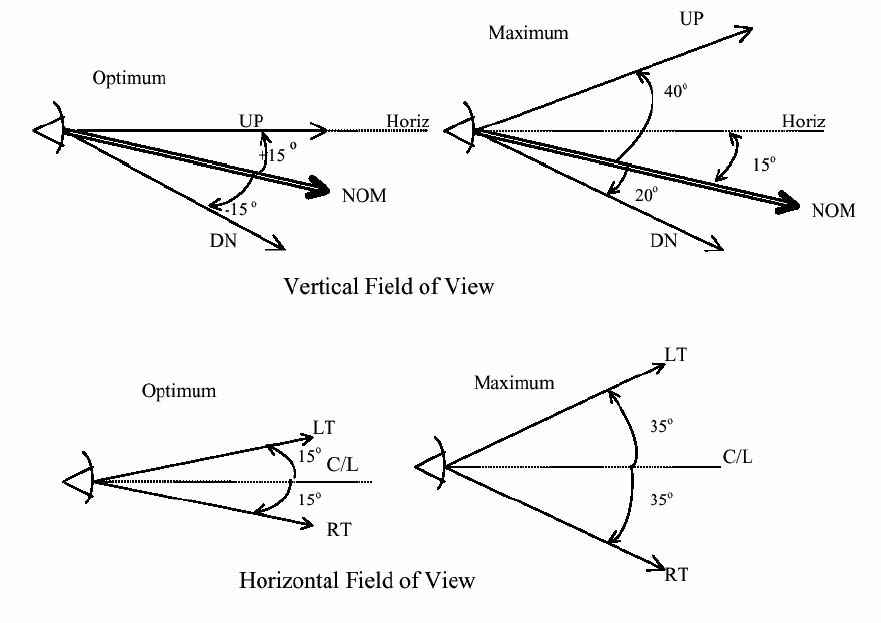
Figure A3-1 Primary Field of View
Primary Flight Information- The information whose presentation
is required by CS 25.1303(b) and CS 25.1333(b), and arranged by CS 25.1321(b).
Primary Flight Instrument - Any display or instrument that
serves as the flight crew’s primary reference of a specific parameter of
primary flight information. For example, a centrally located attitude director
indicator is a primary flight instrument because it is the flight crew’s
primary reference for pitch, bank, and command steering information.
Prompt- A method of cueing the flight crew that some
input or action is required.
Required Engine Indications- The information whose presentation
is required by CS 25.1305.
Reversionary - The automatic or flight crew initiated
(manual) relocation of display formats or windows following a display failure.
Shading - Shading is used as:
—
A
coding method for separating information, change in state, give emphasis, and
depth information.
—
A
blending method between graphic elements (map displays, synthetic vision
system).
Soft Control- Display element used to manipulate, select, or
de-select information (for example, menus and soft keys).
Standby Display- A backup display that is used if a primary
display malfunctions.
Status information - Information about the current
condition of an aeroplane system and its surroundings.
Symbol - A symbol is a geometric form or alpha-numeric
information used to represent the state of a parameter on a display. The
symbol may be further defined by its location and motion on a display.
Synthetic Vision – A computer generated image of the
external topography from the perspective of the flight deck. The image is
derived from aircraft attitude, high-precision navigation solution, and
terrain database terrain, obstacles, and relevant cultural features.
Synthetic Vision System – An electronic means to display a
synthetic vision image of the external scene topography to the flight crew.
Texturing - A graphic, pictorial effect used to give a
displayed object or graphic a specific “look” (metallic, grassy, cloudy,
etc.). Texture is used:
—
As
a coding method for separating information, change in state, give emphasis,
and depth information.
—
As
a blending method between graphic elements (map displays, synthetic vision
system).
—
To
enhance similarity between a synthetic image and the real world image.
Time Sharing – Showing different information in the same
display area at different times.
Transparency- A means of seeing a background information
element through a foreground information element. Transparency can alter the
colour perception of both the “front” element and the “back” element.
Viewing Angle – The angle between the normal line of sight
(looking straight ahead) and the line from the eye to the object being viewed.
The angle can be horizontal, vertical, or a composite of those two angles.
Window (See Figure A3-2) - A rectangular physical area of
the display surface. A window consists of one or more layers (see ARINC
Specification 661).
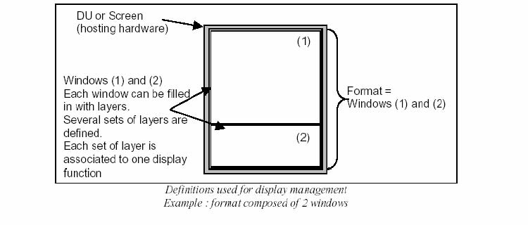
Windowing - The technique to create windows. Segmenting
a single display area into two or more independent display areas or inserting
a new display area onto an existing display.
[Amdt
25/11]