AMC
25.963(d) Fuel tank strength in emergency landing conditions
ED Decision 2007/010/R
1. PURPOSE.
This AMC sets forth an acceptable means, but not the only means, of
demonstrating compliance with the provisions of CS-25 related to the strength
of fuel tanks in emergency landing conditions.
2. RELATED
CERTIFICATION SPECIFICATIONS.
CS 25.561
“Emergency Landing Conditions – General”,
CS 25.721
“Landing Gear – General”
CS 25.994 “Fuel
System Components”
CS 25J994 “Fuel
System Components”
3. BACKGROUND.
For many years the JAA/EASA has required fuel tanks within the fuselage
contour to be designed to withstand the inertial load factors prescribed for
the emergency landing conditions as specified in JAR/CS 25.561. These load
factors have been developed through many years of experience and are generally
considered conservative design criteria applicable to objects of mass that
could injure occupants if they came loose in a minor crash landing.
a. A minor
crash landing is a complex dynamic condition with combined loading. However,
in order to have simple and conservative design criteria, the emergency
landing forces were established as conservative static ultimate load factors
acting in each direction independently.
b. Recognising
that the emergency landing load factors were applicable to objects of mass
that could cause injury to occupants and that the rupture of fuel tanks in the
fuselage could also be a serious hazard to the occupants, § 4b.420 of the
Civil Air Regulations (CAR) part 4b (the predecessor of FAR 25) extended the
emergency landing load conditions to fuel tanks that are located within the
fuselage contour. Even though the emergency landing load factors were
originally intended for solid items of mass, they were applied to the liquid
fuel mass in order to develop hydrostatic pressure loads on the fuel tank
structure. The application of the inertia forces as a static load criterion
(using the full static head pressure) has been considered a conservative criterion
for the typical fuel tank configuration within the fuselage contour. This
conservatism has been warranted considering the hazard associated with fuel
spillage.
c. CS 25.963 has required that
fuel tanks, both in and near the fuselage, resist rupture under survivable
crash conditions. The advisory material previously associated with CS 25.963
specifies design requirements for all fuel tanks that, if ruptured, could
release fuel in or near the fuselage or near the engines in quantities
sufficient to start a serious fire.
d. In
complying with this CS requirement for wing tanks, several different
techniques have been used by manufacturers to develop the fuel tank pressure
loads due to the emergency landing inertia forces. The real emergency landing
is actually a dynamic transient condition during which the fuel must flow in a
very short period of time to re-establish a new level surface normal to the
inertial force. For many tanks such as large swept wing tanks, the effect is
that the actual pressure forces are likely to be much less than that which
would be calculated from a static pressure based on a steady state condition
using the full geometric pressure head. Because the use of the full pressure
head results in unrealistically high pressures and creates a severe design penalty
for wing tanks in swept wings, some manufacturers have used the local
streamwise head rather than the full head. Other manufacturers have used the
full pressure head but with less than a full tank of fuel. These methods of
deriving the pressures for wing tanks have been accepted as producing design
pressures for wing tanks that would more closely represent actual emergency
landing conditions. The service record has shown no deficiency in strength for
wing fuel tanks designed using these methods.
e. FAR 25
did not contain a requirement to apply fuel inertia pressure requirements to
fuel tanks outside the fuselage contour, however, the FAA (like the JAA) has
published Special Conditions to accomplish this for fuel tanks located in the
tail surfaces. The need for Special Conditions was justified
by the fact that these tanks are located in a rearward position from which
fuel spillage could directly affect a large portion of the fuselage, possibly
on both sides at the same time.
4. GENERAL.
CS 25.963(d) requires that fuel tanks must be designed, located, and installed so
that no fuel is released in quantities sufficient to start a serious fire in
otherwise survivable emergency landing conditions. The prescribed set of
design conditions to be considered is as follows:
a. Fuel
tank pressure loads. CS 25.963(d)(1) provides a conservative method for
establishing the fuel tank ultimate emergency landing pressures. The phrase
“fuel tanks outside the fuselage contour” is intended to include all fuel
tanks where fuel spillage through any tank boundary would remain physically
and environmentally isolated from occupied compartments by a barrier that is
at least fire resistant as defined in CS-Definitions. In this regard, cargo
compartments that share the same environment with occupied compartments would
be treated the same as if they were occupied. The ultimate pressure criteria
are different depending on whether the fuel tank under consideration is
inside, or outside the fuselage contour. For the purposes of this paragraph a
fuel tank should be considered inside the fuselage contour if it is inside the
fuselage pressure shell. If part of the fuel tank pressure boundary also forms
part of the fuselage pressure boundary then that part of the boundary should
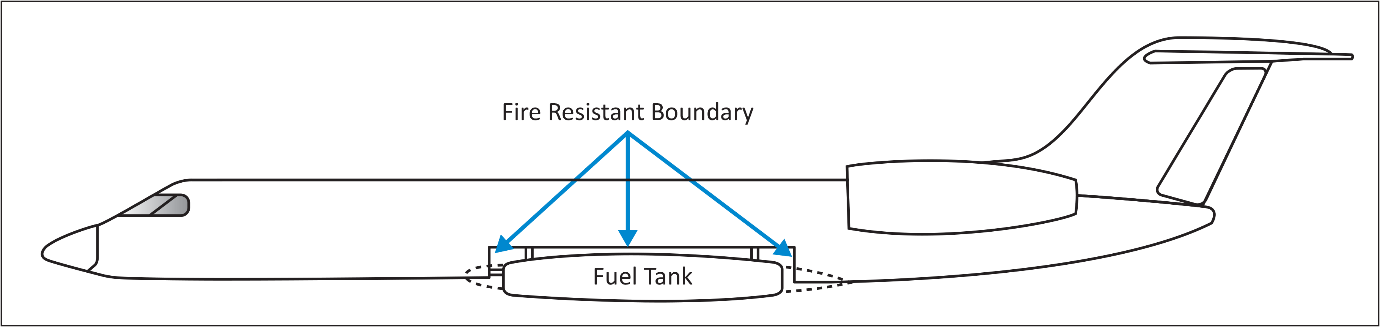
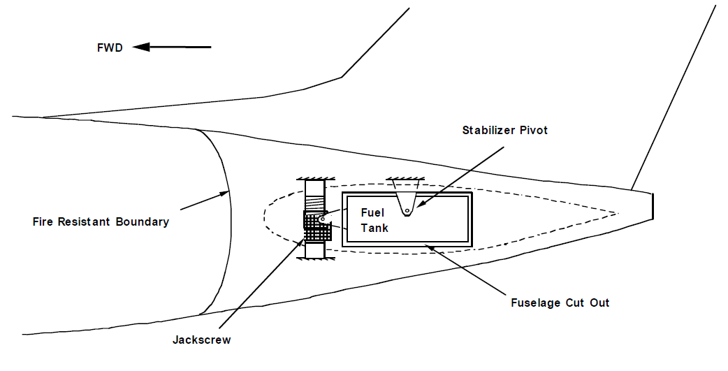
be considered as being within the fuselage contour. Figures 1 and 2 show
examples of an underslung wing fuel tank and a fuel tank within a moveable
tailplane, respectively, both of which would be considered as being entirely
outside of the fuselage contour.
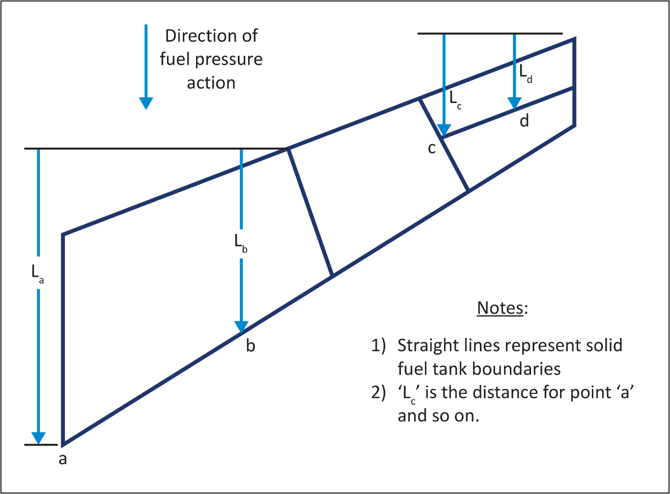
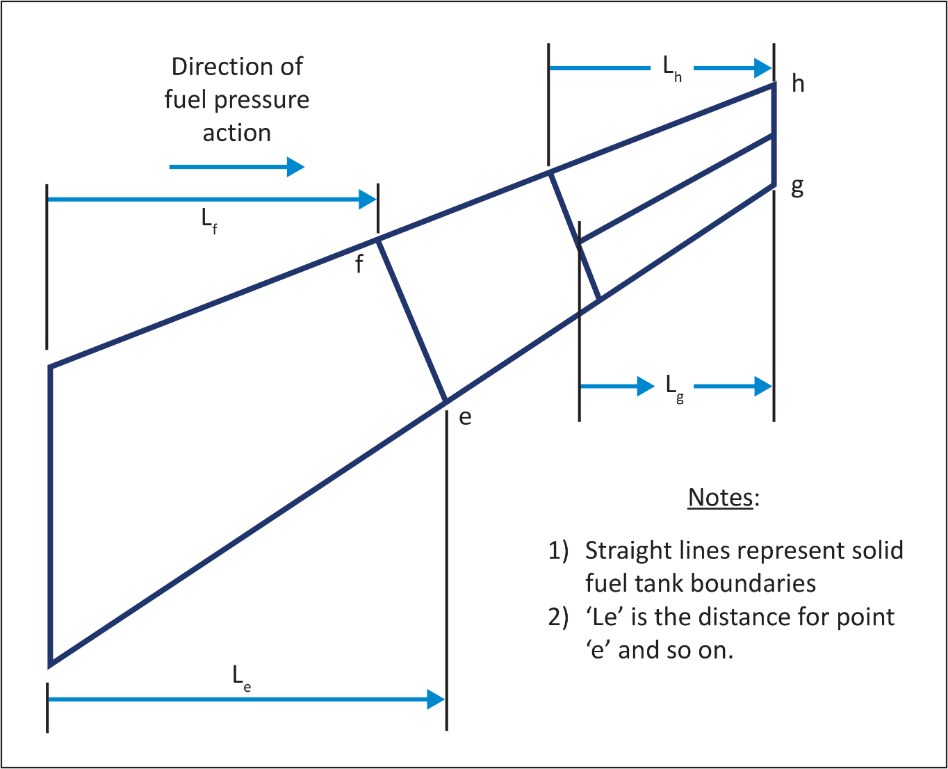
The equation for fuel tank pressure uses a factor L, based upon fuel
tank geometry. Figure 3 shows examples of the way L is calculated for fuel
pressures arising in the forward loading condition, while Figure 4 shows
examples for fuel pressures arising in the outboard loading condition.
For Jet A(-1) fuel, a typical density of 785.0 kg/m3 (6.55 lb/US
gallon) may be assumed.
Any internal barriers to free flow of fuel may be considered as a solid
pressure barrier provided:
(1) It can
withstand the loads due to the expected fuel pressures arising in the
conditions under consideration; and
(2) The time “T” for fuel to flow from the upstream side of the barrier to fill the cell downstream of the barrier is greater than 0.5 second. “T” may be conservatively estimated as:
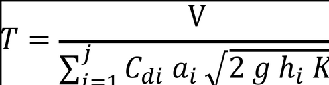
where:
V= the
volume of air in the fuel cell downstream of the barrier assuming a full tank
at 1g flight conditions. For this purpose a fuel cell should be considered as
the volume enclosed by solid barriers. In lieu of a more rational analysis, 2%
of the downstream fuel volume should be assumed to be trapped air;
j = the
total number of orifices in baffle rib;
Cdi = the
discharge coefficient for orifice i. The discharge coefficient may be
conservatively assumed to be equal to 1.0 or it may be rationally based upon
the orifice size and shape;
ai = the area
for orifice i;
g = the
acceleration due to gravity;
hi = the
hydrostatic head of fuel upstream of orifice i, including all fuel volume
enclosed by solid barriers;
K = the pressure design factor for the condition under consideration.
b. Near the
fuselage/near the engines (Compliance with CS 25.963(d)(2).)
(1) For
aircraft with wing mounted engines:
(i) The
phrase “near the fuselage” is addressing those (parts of) wing fuel tanks
located between the fuselage and the most inboard engine;
(ii) The
phrase “near the engine” is addressing those (parts of) wing fuel tanks as
defined in AMC 20-128A, figure 2, minimum distance of 10 inches (254 mm)
laterally from potential ignition sources of the engine nacelle.
(2) For
aircraft with fuselage mounted engines, the phrase “near the fuselage” is
addressing those (parts of) wing fuel tanks located within one maximum
fuselage width outside the fuselage boundaries.
c. Protection
against crushing and scraping action (Compliance with CS 25.963(d)(4) and CS 25.721(b) and (c).).
Each fuel tank should be protected against the effects of crushing and
scraping action (including thermal effects) of the fuel tank and surrounding
airframe structure with the ground under the following minor crash landing
conditions:
(i) An
impact at 1.52 m/s (5 fps) vertical velocity on a paved runway at maximum
landing weight, with all landing gears retracted and in any other possible
combination of gear legs not extended. The unbalanced pitching and rolling
moments due to the ground reactions are assumed to be reacted by inertia and
by immediate pilot control action consistent with the aircraft under control
until other structure strikes the ground. It should be shown that the loads
generated by the primary and subsequent impacts are not of a sufficient level
to rupture the tank. A reasonable attitude should be selected within the speed
range from VL1 to 1.25 VL2 based upon the fuel tank arrangement.
VL1 equals to VS0 (TAS) at the appropriate landing weight and in
standard sea-level conditions, and VL2 equals to VS0 (TAS) at the appropriate
landing weight and altitudes in a hot day temperature of 22.8 degrees C (41
degrees F) above standard.
(ii) Sliding
on the ground starting from a speed equal to VL1 up to complete stoppage, all
gears retracted and with up to a 20° yaw angle and as a separate condition,
sliding with any other possible combination of gear legs not extended and with
a 0° yaw angle. The effects of runway profile need not be considered.
(iii) The
impact and subsequent sliding phases may be treated as separate analyses or as
one continuous analysis. Rational analyses that take into account the pitch
response of the aircraft may be utilised, however care must be taken to assure
that abrasion and heat transfer effects are not inappropriately reduced at
critical ground contact locations.
(iv) For
aircraft with wing mounted engines, if failure of engine mounts, or failure of
the pylon or its attachments to the wing occurs during the impact or sliding
phase, the subsequent effect on the integrity of the fuel tanks should be
assessed. Trajectory analysis of the engine/pylon subsequent to the separation
is not required.
(v) The
above emergency landing conditions are specified at maximum landing weight,
where the amount of fuel contained within the tanks may be sufficient to
absorb the frictional energy (when the aircraft is sliding on the
ground)without causing fuel ignition. When lower fuel states exist in the
affected fuel tanks these conditions should also be considered in order to
prevent fuel-vapour ignition.
d. Engine /
Pylon separation. (Compliance with CS
25.721(c) and CS 25.963(d)(5).)
For configurations where the nacelle is likely to come into contact with the ground, failure under overload should be considered. Consideration should be given to the separation of an engine nacelle (or nacelle + pylon) under predominantly upward loads and under predominantly aft loads. The predominantly upward load and the predominantly aft load conditions should be analysed separately. It should be shown that at engine/pylon failure the fuel tank itself is not ruptured at or near the engine/pylon attachments.
e. Landing
gear separation. (Compliance with CS
25.721(a) and CS 25.963(d)(5).)
Failure of the landing gear under overload should be considered,
assuming the overloads to act in any reasonable combination of vertical and
drag loads, in combination with side loads acting both inboard and outboard.
In the absence of a more rational analysis, the side loads must be assumed to
be up to 20% of the vertical load or 20% of the drag load, whichever is
greater. It should be shown that at the time of separation the fuel tank
itself is not ruptured at or near the landing gear attachments. The assessment
of secondary impacts of the airframe with the ground following landing gear
separation is not required. If the subsequent trajectory of a separated
landing gear would likely puncture an adjacent fuel tank, design precautions
should be taken to minimise the risk of fuel leakage.
f. Compliance
with the provisions of this paragraph may be shown by analysis or tests, or
both.
5. OTHER
CONSIDERATIONS
a. Supporting structure. In accordance with CS 25.561(c) all large mass items that could break loose and cause direct injury to occupants must be restrained under all loads specified in CS 25.561(b). To meet this requirement, the supporting structure for fuel tanks, should be able to withstand each of the emergency landing load conditions, as far as they act in the 'cabin occupant sensitive directions', acting statically and independently at the tank centre of gravity as if it were a rigid body. Where an empennage includes a fuel tank, the empennage structure supporting the fuel tank should meet the restraint conditions applicable to large mass items in the forward direction.
Figure
1: Diagram of Fuel Tank in Underslung Wing that is Outside of the Fire
Resistant Boundary
Figure
2: Diagram of Fuel Tank Within a Movable Tailplane
Figure
3 Example of Distances for Fuel Forward Acting Design Pressure Calculations
Figure
4 – Example of Distances for Fuel Outboard Acting Design Pressure Calculations
[Amdt 25/3]