AMC 25.1709 System safety; EWIS
ED
Decision 2008/006/R
25.1709
requires applicants to perform a system safety assessment of the EWIS. The
analysis required for compliance with CS 25.1709 is based on a qualitative approach
to assessing EWIS safety as opposed to numerical, probability-based
quantitative analysis. The safety assessment must consider the effects that
both physical and functional failures of EWIS would have on aeroplane safety.
That safety assessment must show that each EWIS failure considered hazardous
is extremely remote. It must show that each EWIS failure considered to be
catastrophic is extremely improbable and will not result from a single
failure.
1 Objective.
The
objective of CS 25.1709 is to use the concepts of CS 25.1309
to provide a thorough and structured analysis of aircraft wiring and its
associated components. As in CS 25.1309, the fail-safe design concept applies.
Any single failure condition, such as an arc fault, should be assumed to occur
regardless of probability.
2 Inadequacies of CS 25.1309
in relation to EWIS safety assessments.
CS 25.1309
requires the applicant to perform system safety assessments. But current CS
25.1309 practice has not led to the type of analysis that fully ensures all
EWIS failure conditions affecting aeroplane level safety are considered. This
is because wiring for non-required systems is sometimes ignored. Even for
systems covered by CS 25.1309(b), the safety analysis requirements have not
always been applied to the associated wire. When they are, there is evidence
of inadequate and inconsistent application. Traditional thinking about
non-required systems, such as IFE, has been that, since they are not required,
and the function they provide is not necessary for the safety of the
aeroplane, their failure could not affect the safety of the aeroplane. This is
not a valid assumption. Failure of an electrical wire, regardless of the
system it is associated with, can cause serious physical and functional damage
to the aeroplane, resulting in hazardous or even catastrophic failure
conditions. An example of this is arcing from a shorted wire cutting through
and damaging flight control cables. There are more failure modes than have
been addressed with traditional analyses. Some further examples are arcing
events that occur without tripping circuit breakers, resulting in complete
wire bundle failures and fire; or wire bundle failures that lead to structural
damage
3 Integrated nature of EWIS.
The
integrated nature of wiring and the potential severity of failures demand a
more structured safety analysis approach than that traditionally used under CS 25.1309. CS 25.1309 system safety
assessments typically evaluate effects of wire failures on system functions.
But they have not considered physical wire failure as a cause of the failure
of other wires within the EWIS. Traditional assessments look at external
factors like rotor burst, lightning, and hydraulic line rupture, but not at
internal factors, like a single wire chafing or arcing event, as the cause of
the failure of functions supported by the EWIS. Compliance with CS 25.1709
requires addressing those failure modes at the aeroplane level. This means
that EWIS failures need to be analyzed to determine what effect they could
have on the safe operation of the aeroplane.
4 Compliance summary.
As specified
above, the analysis required for compliance with CS 25.1709
is based on a qualitative approach to assessing EWIS safety as opposed to
numerical, probability-based quantitative analysis. The intent is not to
examine each individual wire and its relation to other wires. Rather, it is to
ensure that there are no combinations of failures that could lead to a
hazardous condition. However, in case the “top down” analysis process
described in this AMC determines that a failure in a given bundle may lead to
a catastrophic failure condition, the mitigation process may lead to
performing a complete analysis of each wire in the relevant bundle.
5 Qualitative probability terms.
When using
qualitative analyses to determine compliance with CS 25.1709,
the following descriptions of the probability terms have become commonly
accepted as aids to engineering judgment:
a. Extremely remote failure conditions.
These are
failure conditions that are not anticipated to occur to an individual
aeroplane during its total life but which may occur a few times when
considering the total operational life of all aeroplanes of the type.
b. Extremely improbable failure conditions.
These are
failure conditions so unlikely that they are not anticipated to occur during
the entire operational life of all aeroplanes of one type.
6 Relationship to CS 25 system safety
assessments.
The analysis
described may be accomplished in conjunction with the required aircraft system
safety assessments of CS 25.1309, 25.671, etc.
7 Classification of failure terms.
The
classification of failure conditions is specified in AMC 25.1309.
8 Flowcharts depicting the analysis
process.
Flowcharts 1
and 2 outline one method of complying with the requirements of CS 25.1709.
The processes in both Flowcharts 1 and 2 identify two aspects of the analysis:
physical failures and functional failures. The processes described in both
flowcharts begins by using the aircraft level functional hazard analysis
developed for demonstrating compliance with CS 25.1309 to identify catastrophic and
hazardous failure events. A step-by-step explanation of the analysis depicted
in the flowcharts is given in paragraphs 11 (for flowchart 1) and 12 (for
Flowchart 2).
a. Flowchart 1.
This
flowchart applies to applicants for pre-TC work and for amended TCs, and STCs
when the applicant has all data necessary to perform the analysis. If
Flowchart 1 is used for post-TC modifications the available data must include
identification of the systems in the EWIS under consideration for modification
and the system functions associated with that EWIS.
b. Flowchart 2.
This
flowchart applies to applicants for post-TC modifications when the applicant
cannot identify the systems or systems functions contained in EWIS under
consideration for modification.
9 Definitions applicable to CS 25.1709.
For this
discussion the following definitions apply:
a. Validation. Determination that requirements
for a product are sufficiently correct and complete.
b. Verification. Evaluation to determine
that requirements have been met.
c. Mitigation. Elimination of the hazard
entirely or suitable precautions taken to minimize the overall severity to an
acceptable level.
10 Physical failure analysis.
a. Only single common cause events or
failures need to be addressed during the physical failure analysis as
described in this AMC and shown on the left hand sides of Flowcharts 1 and 2.
Multiple common cause events or failures need not be addressed.
b. In relation to physical effects, it
should be assumed that wires are carrying electrical energy and that, in the
case of an EWIS failure, this energy may result in hazardous or catastrophic
effects directly or when combined with other factors, for example fuel,
oxygen, hydraulic fluid, or damage by passengers, These failures may result in
fire, smoke, emission of toxic gases, damage to co-located systems and
structural elements or injury to personnel. This analysis considers all EWIS
from all systems (autopilot, auto throttle, PA system, IFE systems, etc.)
regardless of the system criticality.
Flowchart 1: Pre- and Post-Type
Certification Safety Analysis Concept
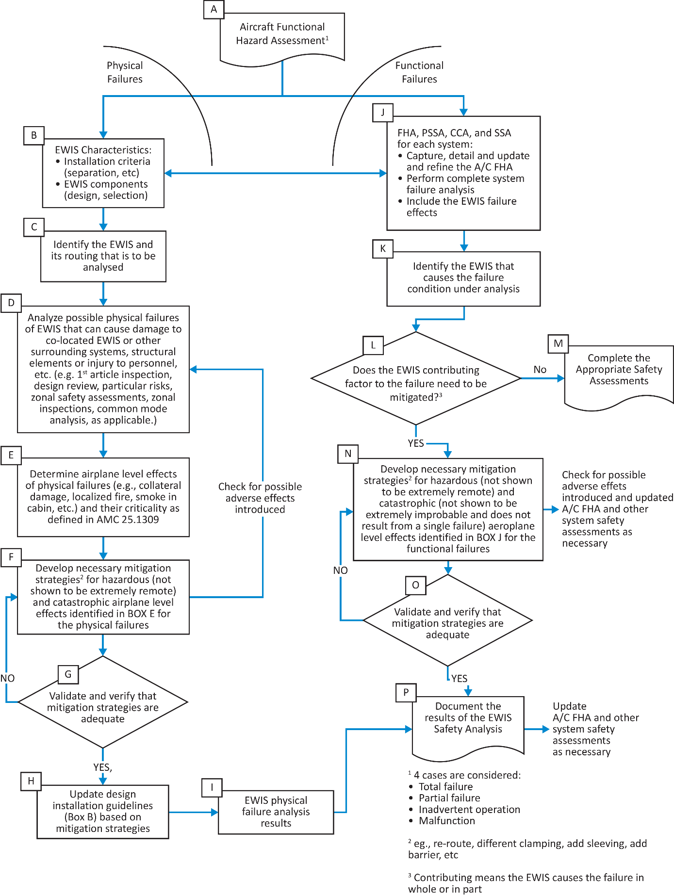
Note: Mitigation as used in this flowchart means
to eliminate the hazard entirely or minimise its severity to an acceptable
level.
11 Descriptive
text for flowchart 1
a. Box A: Aircraft functional hazard
assessment.
(1) The functional failure analysis assumes
that electrical wires are carrying power, signal, or information data. Failure
of EWIS under these circumstances may lead to aircraft system degradation
effects.
(2) The functional hazard assessment (FHA)
referred to in this box is not a stand-alone separate document specifically
created to show compliance with CS 25.1709. It is the aircraft level FHA that
the applicant will have developed in compliance with CS 25.1309 to help demonstrate acceptability
of a design concept, identify potential problem areas or desirable design
changes, or determine the need for and scope of any additional analyses (refer
to AMC 25.1309)
b. Analysis of Possible Physical Failures
(1) Box B: EWIS characteristics.
Use the
results of the FHA (BOX A and BOX J) to identify EWIS installation criteria
and definitions of component characteristics. Results from BOX B are fed into
the preliminary system safety analysis (PSSA) and system safety analysis (SSA)
of BOX J.
(2) Boxes C, D and E: Validation and
verification of installation criteria.
(i) Ensure that the EWIS component
qualification satisfies the design requirements and that components are
selected, installed, and used according to their qualification characteristics
and the aircraft constraints linked to their location (refer to the requirements
of CS 25.1703 and CS 25.1707).
(ii) Use available information (digital
mock-up, physical mock-up, aeroplane data, historical data) to perform
inspections and analyses to validate that design and installation criteria are
adequate to the zone/function, including considerations of multi-systems
impact. Such inspections and analyses may include a 1st article inspection,
design review, particular risk assessment, zonal safety assessment, zonal
inspection, and common mode analysis, as applicable. Use such assessments and
inspections to ascertain whether design and installation criteria were
correctly applied. Special consideration should be given to known problem
areas identified by service history and historical data (areas of arcing,
smoke, loose clamps, chafing, arc tracking, interference with other systems,
etc.). Regardless of probability, any single arcing failure should be assumed
for any power-carrying wire. The intensity and consequence of the arc and its
mitigation should be substantiated. Give special consideration to cases where
new (previously unused) material or technologies are used. In any case CS 25.1703(b)
requires that the selection of wires must take into account known
characteristics in relation to each installation and application to minimise
the risk of wire damage, including any arc tracking phenomena.
(iii) Deviations from installation and component
selection criteria identified by these activities should be evaluated. A
determination can then be made about their acceptability. Develop alternative
mitigation strategies as necessary.
(3) Boxes F and G: Development and validation
of mitigation strategy.
Identify and
develop a mitigation strategy for the physical failures and their adverse
effects identified in Boxes D and E. Validation and verification of the
mitigation solution should ensure that:
(i) Hazardous failure conditions are
extremely remote.
(ii) Catastrophic failure conditions do not
result from a single common cause event or failure.
(iii) This mitigation solution does not
introduce any new potential failure conditions.
(4) Box H: Incorporation of applicable
mitigation strategies.
Incorporate
newly developed mitigation strategies (BOX F) into guidelines (BOX B) for
further design and inspection and analysis processes.
(5) Box I: Physical failure analysis results.
From the
EWIS physical failure analysis, the following should be documented:
—
Physical
failures addressed.
—
Effects
of those physical failures.
—
Mitigation
strategies developed.
This
information should be used to support the final analysis documentation (BOX P).
c. Analysis of Possible Functional Failures
(1) Box J: System safety assessments.
The results
of the aeroplane level FHA (BOX A) should be used to guide the system level
FHA (BOX J). Incorporate EWIS failures identified by CS 25.1709 into the
system level and aircraft level FHA, the PSSA, the Common Cause Analyses
(CCA), and the SSA. These analyses are performed to satisfy requirements of CS 25.1309. Use results of these analyses to
update the EWIS definition (BOX B).
(2) Boxes K, L and M: Hazardous and
catastrophic failure conditions.
Use the
analyses in BOX J to determine if the EWIS associated with the system under
analysis can contribute (in whole or in part) to the failure condition under
study. Determine whether the EWIS failure needs to be mitigated. If so,
develop, validate, and verify a mitigation strategy. If no mitigation is
needed, complete the appropriate safety assessment per CS 25.1309, CS 25.671, etc..
(3) Boxes N and O: Development and validation
of mitigation strategy.
Identify and
develop a mitigation strategy for the functional failures and adverse effects
identified in BOX J. Validation and verification of the mitigation solution
should determine if initial objective is fully reached; and confirm that this
mitigation solution is compatible with existing installations and installation
criteria. If the EWIS was the failure cause, the subsequent mitigation
strategy developed may introduce new adverse effects not previously identified
by the analysis. Check for any new adverse effects and update the aircraft
level FHA and other system safety assessments as necessary.
(4) Box P: Documentation of EWIS safety
analysis results.
After
mitigation strategies have been validated and verified, the results of the CS 25.1709 analysis should be documented. Update as necessary the aircraft level
FHA that has been developed in support of certification of the proposed
modification, in compliance with CS 25.1309 (BOX A).
Flowchart 2: Post-TC Safety
Analysis Concept
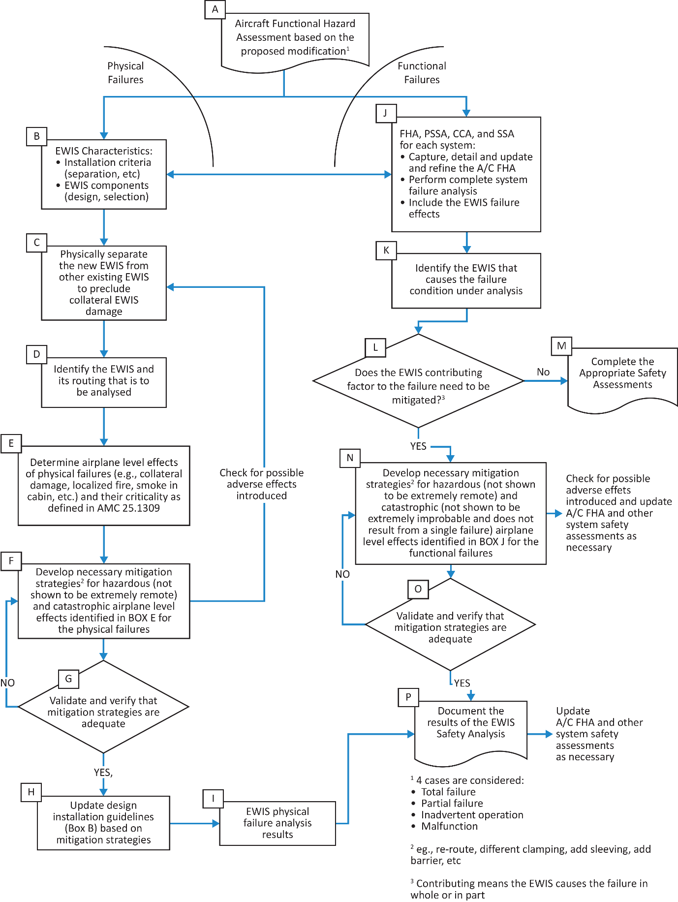
Note: Mitigation as used in this flowchart means to
eliminate the hazard entirely or minimise its severity to an acceptable level.
12 Descriptive
text for flowchart 2.
a. Applicants for post-TC modifications
should use the analysis depicted in Flowchart 2 when the applicant cannot
identify the systems or systems functions contained in existing aircraft EWIS
that maybe utilized as part of the modification. An applicant should not add
EWIS to an existing EWIS if the systems or systems functions contained in the
existing EWIS are unknown. To do so could introduce unacceptable hazards. For
example, IFE power wires could inadvertently be routed with aeroplane autoland
EWIS.
b. The main objectives are to ensure that
the proposed modification will be correctly designed and installed and will
not introduce unacceptable hazards either through its own failure or by
adversely affecting existing aircraft systems. As far as EWIS is concerned,
correct incorporation of the modification should be ensured by both good
knowledge of original aircraft manufacturer installation practices and their
correct implementation or by adequate separation of the added EWIS from
existing EWIS. In either case, physical analyses should be performed (similar
to the physical failures part of Flowchart 1).
c. Box A: Aircraft functional hazard
assessment.
Aircraft
level effects must be considered for modified systems or systems added to the
aircraft. If the Aircraft level FHA is available, the applicant should examine
it to determine the Aircraft level effect of the proposed modification. If the
Aircraft level FHA is not available, then the applicant must generate an
Aircraft level FHA based on the proposed modification. This Aircraft level FHA
would be limited to just those Aircraft systems affected by the proposed
modification. If it is determined that no Aircraft level functional effects
are introduced, a statement to this effect and the supporting data is
sufficient to satisfy BOX A.
d. Analysis of Possible Physical Failures
(1) Box B: EWIS characteristics.
Use results
of the Aircraft level FHA (BOX A and BOX J) to identify EWIS installation
criteria and definitions of component characteristics. Results of BOX B are
fed into the PSSA and SSA of BOX J.
(2) Box C: Physical separation of new EWIS
from existing EWIS.
(i) The EWIS to be added should be separated
from existing aeroplane EWIS since the systems or system functions contained
in the existing EWIS are unknown. Physical separation between the new and
existing EWIS should be established either by separation distance or by an
appropriate barrier or other means shown to be at least equivalent to the
physical separation distance when allowed by CS 25.1707.
Alternative methods given in the advisory material for CS 25.1707
provide an acceptable way to determine adequate separation.
(ii) In cases where separation cannot be
maintained because of physical constraints (e.g., terminal strips and
connectors), the applicant should accomplish the appropriate analysis to show
that no adverse failure conditions result from sharing the common device. This
analysis requires knowledge of the systems or system functions sharing the
common device (e.g., terminal strips and connectors).
(3) Box D and E: Validation and verification
of installation criteria.
(i) Ensure that the EWIS component
qualification satisfies the design requirements and that components are
selected, installed, and used according to their qualification characteristics
and the aeroplane constraints linked to their location.
(ii) Use available information (digital
mock-up, physical mock-up, aeroplane data, historical data) to perform
inspections and analyses to validate that design and installation criteria are
adequate to the zone/function, including considerations of multi-systems
impact. Such inspections and analyses may include a 1st article inspection,
design review, particular risk assessment, zonal safety assessment, zonal
inspection, and common mode analysis, as applicable. Use such assessments and
inspections to ascertain whether design and installation criteria were
correctly applied. Special consideration should be given to known problem
areas identified by service history and historical data (areas of arcing,
smoke, loose clamps, chafing, arc tracking, interference with other systems,
etc.). Regardless of probability, any single arcing failure should be assumed
for any power-carrying wire. The intensity and consequence of the arc and its
mitigation should be substantiated. Special consideration should be given to cases
where new (previously unused) material or technologies are used. Evaluate
deviations from installation and component selection criteria identified by
these activities and determine their acceptability.
(iii) Alternative mitigation strategies should
be developed as necessary.
(4) Boxes F and G: Development and validation
of mitigation strategy.
Identify and
develop a mitigation strategy for the physical failures identified in BOXES D
and E and resulting adverse effects. Validation and verification of a
mitigation solution should ensure that:
(i) Hazardous failure conditions are
extremely remote.
(ii) Catastrophic failure conditions do not
result from a single common cause event or failure.
(iii) This mitigation solution does not
introduce any new potential failure conditions.
(5) Box H: Incorporation of Applicable
Mitigation Strategies.
Incorporate
newly developed mitigation strategies (BOX F) into guidelines (BOX B) for
further design and inspection and analysis process.
(6) Box I: Physical failure analysis
documentation.
From the
EWIS physical failure analysis, the following should be documented:
—
Physical
failures addressed.
—
Effects
of those physical failures.
—
Mitigation
strategies developed.
This
information supports the final analysis documentation (BOX P).
e. Analysis of Possible Functional Failures
(1) Box J: System safety assessments.
Use the
results of the aircraft level FHA (BOX A) to guide the system level FHA
(BOX J). Incorporate EWIS failures identified by CS 25.1709
into the system level and aircraft level FHA, the PSSA, the CCA, and the SSA.
These analyses are performed to satisfy requirements of CS 25.1309. Use results of these analyses to
update the EWIS definition (BOX B).
(2) Boxes K, L and M: Hazardous and
catastrophic failure conditions.
Use the
analyses in BOX J to determine if the EWIS associated with the system under
analysis can contribute (in whole or in part) to the failure condition under
study. Determine whether the EWIS failure needs to be mitigated. If so,
develop, validate, and verify a mitigation strategy. If no mitigation is
needed, complete the appropriate safety assessment (e.g., per CS 25.1309,
CS 25.671, etc.).
(3) Boxes N and O: Development and validation
of mitigation strategy.
Identify and
develop a mitigation strategy for the functional failures and adverse effects
identified in BOX J. Validation and verification of the mitigation solution
should determine if initial objective is fully reached and confirm that this
mitigation solution is compatible with existing installations and installation
criteria. If the EWIS was the failure cause, the subsequent mitigation
strategy developed may introduce new adverse effects not previously identified
by the analysis. Check for any new adverse effects and update the aircraft
level FHA and other system safety assessments as necessary.
(4) Box P: Documentation of EWIS safety
analysis results.
After
mitigation strategies have been validated and verified, document the results
of the CS 25.1709 analysis. Update as necessary the aircraft
level FHA that has been developed in support of certification of the proposed
modification, in compliance with CS 25.1309, (BOX A).
[Amdt
25/5]