CS
ADR-DSN.M.645 Precision approach path indicator and Abbreviated precision
approach path indicator (PAPI and APAPI)
ED Decision 2017/021/R
(a) A PAPI or APAPI should be in accordance with the specifications provided in paragraphs CS ADR-DSN.M.645 to CS ADR-DSN.M.655.
(b) Definition and positioning:
(1) The PAPI system should consist of a wing bar of four sharp transition multi-lamp (or paired single lamp) units equally spaced. The APAPI system should consist of a wing bar of two sharp transition multi-lamp (or paired single lamp) units. The PAPI and APAPI system should be located on the left side of the runway unless it is physically impracticable to do so. Where a runway is used by aircraft requiring visual roll guidance which is not provided by other external means, then a second wing bar may be provided on the opposite side of the runway for PAPI or APAPI.
(2) The wing bar of a PAPI should be constructed and arranged in such a manner that a pilot making an approach should:
(i) when on or close to the approach slope, see the two units nearest the runway as red and the two units farthest from the runway as white;
(ii) when above the approach slope, see the one unit nearest the runway as red and the three units farthest from the runway as white; and when further above the approach slope, see all the units as white; and
(iii) when below the approach slope, see the three units nearest the runway as red and the unit farthest from the runway as white; and when further below the approach slope, see all the units as red.
(3) The wing bar of an APAPI should be constructed and arranged in such a manner that a pilot making an approach should:
(i) when on or close to the approach slope, see the unit nearer the runway as red and the unit farther from the runway as white;
(ii) when above the approach slope, see both the units as white; and
(iii) when below the approach slope, see both the units as red.
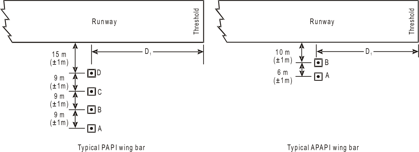
(4) The light units should be located as in the basic configuration illustrated in Figure M-4, subject to the installation tolerances given below. The units forming a wing bar should be mounted so as to appear to the pilot of an approaching aeroplane to be substantially in a horizontal line. The light units should be mounted as low as possible and should be frangible.
(c) Characteristics:
(1) The system should be suitable for both day and night operations.
(2) Colour:
(i) The colour transition from red to white in the vertical plane should be such as to appear to an observer, at a distance of not less than 300 m, to occur within a vertical angle of not more than 3´.
(ii) At full intensity, the chromaticity of lights units should be in accordance with the specifications in CS ADR-DSN.U.930 and Figure U-1A or U-1B, as appropriate, and the red light should have a Y coordinate not exceeding 0.320.
(3) Intensity:
(i) The light intensity distribution of the light units should be as shown in CS ADR-DSN.U.940, Figure U-26.
(ii) Suitable intensity control should be provided so as to allow adjustment to meet the prevailing conditions and to avoid dazzling the pilot during approach and landing.
(4) Light orientation: Each light unit should be capable of adjustment in elevation so that the lower limit of the white part of the beam may be fixed at any desired angle of elevation between 1°30´and at least 4°30´above the horizontal.
(5) Other characteristics: The light units should be so designed that deposits of condensation, snow, ice, dirt, or other contaminants, on optically transmitting or reflecting surfaces should interfere to the least possible extent with the light signals and should not affect the contrast between the red and white signals and the elevation of the transition sector.
|
INSTALLATION
TOLERANCES |
|
|
a) Where
a PAPI or APAPI is installed on a runway not equipped with an ILS or MLS,
the distance D1 should be calculated to ensure that the lowest height at
which a pilot will see a correct approach path indication (Figure M-5, angle
B for a PAPI and angle A for an APAPI) provides the wheel clearance over the
threshold specified in Table M-1 for the most demanding amongst aeroplanes
regularly using the runway. b) Where
a PAPI or APAPI is installed on a runway equipped with an ILS and/or MLS,
the distance D1 should be calculated to provide the optimum compatibility
between the visual and non-visual aids for the range of eye-to-antenna
heights of the aeroplanes regularly using the runway. The distance should be
equal to that between the threshold and the effective origin of the ILS
glide path or MLS minimum glide path, as appropriate, plus a correction
factor for the variation of eye-to-antenna heights of the aeroplanes
concerned. The correction factor is obtained by multiplying the average
eye-to-antenna height of those aeroplanes by the cotangent of the approach
angle. However, the distance should be such that in no case will the wheel
clearance over the threshold be lower than that specified in column (3) of
Table M-1. Note: See CS ADR-DSN.L.540for specifications on
aiming point marking. Further guidance on the harmonisation of PAPI, ILS
and/or MLS signals is contained in ICAO Doc 9157, Aerodrome Design Manual,
Part 4, Visual Aids. |
c) If
a wheel clearance, greater than that specified in a) above is required for
specific aircraft, this can be achieved by increasing D1. d) Distance
D1 should be adjusted to compensate for differences in elevation between the
lens centres of the light units and the threshold. e) To
ensure that units are mounted as low as possible and to allow for any
transverse slope, small height adjustments of up to 5 cm between units
are acceptable. A lateral gradient not greater than 1.25 per cent can be
accepted provided it is uniformly applied across the units. f) A
spacing of 6 m (±1 m) between PAPI units should be used on code numbers
1 and 2. In such an event, the inner PAPI unit should be located not less
than 10 m (±1 m) from the runway edge. Note: Reducing the spacing between light units
results in a reduction in usable range of the system. g) The
lateral spacing between APAPI units may be increased to 9 m (±1 m) if
greater range is required or later conversion to a full PAPI is anticipated.
In the latter case, the inner APAPI unit should be located 15 m (±1 m)
from the runway edge. |
Figure M-4.
Siting of PAPI and APAPI
[Issue: ADR-DSN/3]
[Issue: ADR-DSN/4]