MOC VTOL.2400(c)(3)
Lift/thrust system installation – likely hazards in
operation
n/a
The likely hazards in operation, including hazards to ground personnel, that the applicant should account for, include:
(a) Risk of inadvertent electric engine start (if applicable):
The aircraft controls should prevent inadvertent sudden motor operation when not commanded by the pilot, in particular during the aircraft supply power-on.
(b) Rotor/propeller disk conspicuity during landing, take-off and ground operations (if applicable):
CS 27.1565 Amdt. 6 is accepted as a means of compliance for rotors, propellers and other rotating parts that could hit and injure ground personnel. Considerations for night conditions should also be included if night operations are authorised.
(c) Downwash effect on third parties:
The downwash of the aircraft should be characterised and reported to allow safe operation and minimisation of hazards to ground personnel.
The following method can be followed to test and report aircraft downwash:
(1) Preliminary assessment:
The applicant should assess whether the test as described in this section can be conducted safely for his aircraft.
(2) Test:
While the aircraft is in a low hover, the radial component of the downwash (outwash) is measured around the aircraft on a circle of diameter 2 D.
(3) Reporting:
The maximum measured speed is reported in km/h to the nearest multiple of 5, as well as the measurement standard (here “§(c) in MOC VTOL.2400(c)(3)”), in the performance section of the aircraft flight manual.
If the downwash temperature on the 2 D-diameter circle is more than 10°C above ambient temperature, this should also be characterised and reported.
Note: ‘D’ is reported as part of MOC VTOL.2115.
(4) Test specification:
|
Parameter |
Description |
Value |
Tolerance |
|
Conditions |
density altitude |
≤ 2000 ft |
- |
|
|
ambient wind, throughout each test run, measured 2 m above the ground within 200 m of the circle centre. Location should be representative of the test condition. |
≤ 3 kt |
- |
|
|
no precipitations |
- |
- |
|
Surface |
Smooth pavement, e.g. concrete or asphalt, surrounded by clear area, e.g. grass (Figure 1) |
||
|
|
diameter pavement |
≥ 3 D |
- |
|
|
diameter clear area |
≥ 6 D |
|
|
|
naturally occurring height discontinuity on pavement (excluding measuring equipment and operator, e.g. joint between concrete slabs) |
≤ 2 cm |
- |
|
|
naturally occurring height discontinuity on clear area (e.g. grass) |
≤ 20 cm |
- |
|
|
pavement level (locally and overall) |
0° |
± 2° |
|
|
clear area level (locally and overall) |
0° |
± 5° |
|
Aircraft
position |
Hovering in a normal take-off and landing configuration, holding height or a power datum. Up to 8 poles can be used to assist in visually positioning the aircraft. |
||
|
|
height (from the bottom of the landing gear) |
1 m |
(2) |
|
|
heading |
- |
(2) |
|
|
lateral and longitudinal position |
- |
(2) |
|
|
mass |
MTOM |
-0.1% |
|
|
diameter of poles |
≤ 3 cm |
- |
|
Measurement
positions |
Measuring at discrete locations on the 2 D circle(1) - option 1: While the aircraft is maintained on a fixed heading, successive measurements are taken around the 2 D circle (Figure 2) - option 2: The aircraft is yawed facing successive aiming points while measurements are taken at 4 fixed cardinal positions on the 2 D circle to compensate for residual ambient wind (Figure 3). The measurement intervals at the 4 positions should be synchronised (within ± 1 sec). |
||
|
|
distance between successive measurement positions (option 1) or aiming points (option 2) |
≤ 2 m |
- |
|
|
heights
|
0.5
m and |
± 5 cm |
|
|
lateral and longitudinal position |
- |
± 10 cm |
|
|
measure in the radial direction |
- |
± 5° |
|
|
measure the horizontal wind component |
- |
± 5° |
|
|
measure the maximum over time (for each measurement) |
≥ 10 s |
- |
|
Measuring
support |
An operator and up to 4 poles, or a tripod, can be used to assist in positioning the measuring equipment. The operator and poles should not be located directly in front or behind the measuring equipment. |
||
|
|
diameter of poles or tripod legs |
≤ 3 cm |
- |
|
|
position of operator laterally of measuring equipment |
≥ 2 m |
- |
|
Measuring
equipment |
For example vane anemometer |
||
|
|
accuracy wind speed |
≤ ± 4.5 km/h |
- |
|
|
accuracy temperature (if applicable) |
≤ ± 3°C |
- |
|
|
resolution wind speed |
≤ 1 km/h |
- |
|
|
wind speed reporting interval |
≤ 3 sec (3) |
- |
(1) The 2 D circle should be centred on the centre of the smallest enclosing circle (refer to MOC VTOL.2115 Section 8).
(2) The accuracy of the hover should meet the accuracy expected in operations. Height, heading and lateral/longitudinal position accuracy values could be the “desired” values used to evaluate the handling qualities in hover as per Eurocae ED-295 standard.
(3) or “maximum” reporting function
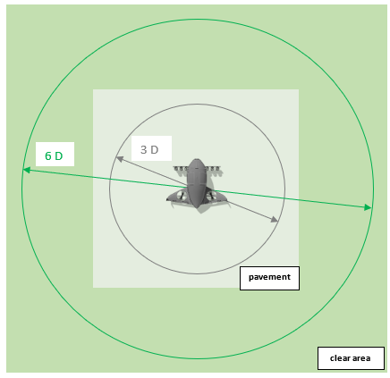
Figure 1: Test surfaces
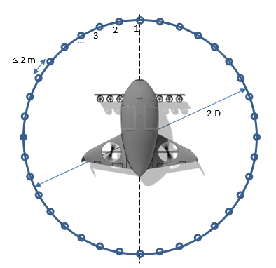
Figure 2: Option 1 – Measurement positions
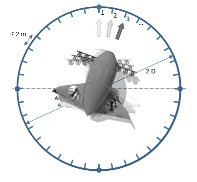
Figure 3: Option 2 – Measurement positions and aiming points
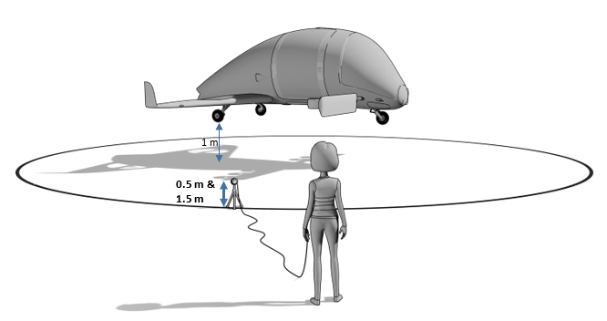
Figure 4: Measurement heights
(d) Hazard areas:
Areas around the aircraft where a hazard to persons or equipment may exist, for example due to moving surfaces, engine exhaust or battery venting in case of fire, should be identified and depicted in the AFM (see example Figure 5). Corresponding hazard markings should be present on the aircraft.
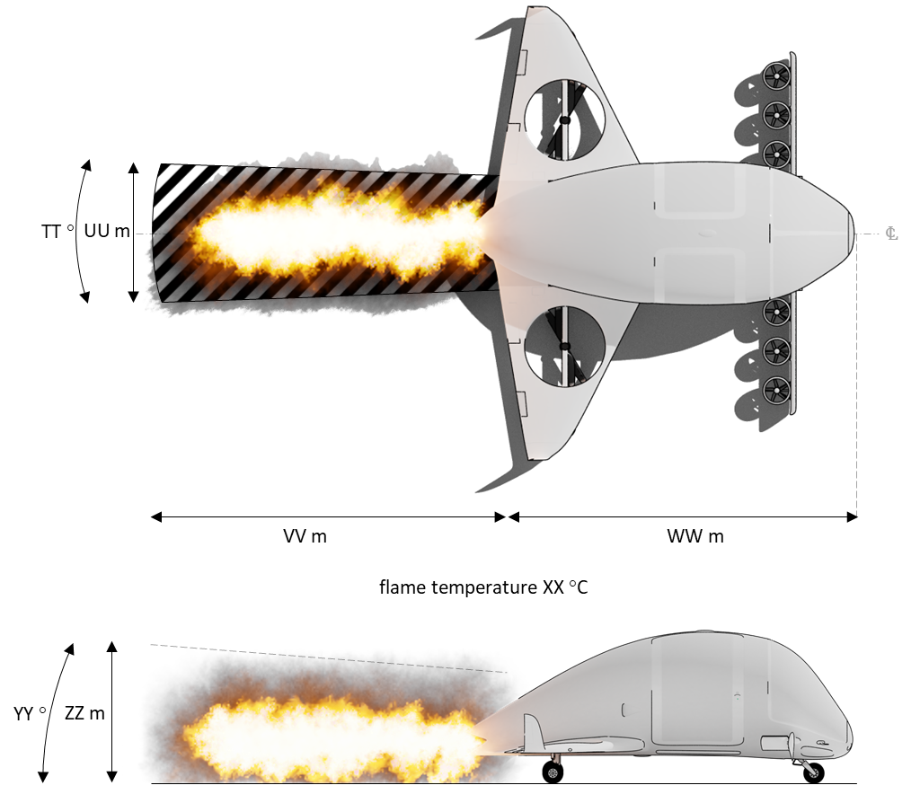
Figure 5: Example of battery fire flame venting hazard area depiction
(e) High Voltage:
Eurocae ED-290 “Guidance on High Voltage definition and Consideration for Personal Safety” is accepted as a means to determine the likely hazards related to High Voltage to be accounted for in VTOL.2400 (c)(3)