AMC
25.963(e) Fuel Tank Protection
ED Decision 2013/033/R
1. PURPOSE. This AMC sets forth a means of compliance with the provisions of CS-25 dealing with the certification requirements for fuel tanks (including skin and fuel tank access covers) on large aeroplanes. Guidance information is provided for showing compliance with the impact and fire resistance requirements of CS 25.963(e).
2. BACKGROUND. Fuel tanks have failed in service due to impact with high speed objects such as failed tyre tread material and engine debris following engine failures. Failure of a fuel tank may result in hazardous fuel leak.
3. IMPACT RESISTANCE.
a. All fuel tanks must be designed to address penetration and deformation by tyre fragments, wheel fragments, small debris from uncontained engine failure or APU failure, or other likely debris (such as runway debris), unless the fuel tanks are located in an area where service experience or analysis indicates a strike is not likely. The rule does not specify rigid standards for impact resistance because of the wide range of likely debris which could impact the fuel tanks. The applicant should, however, choose to minimise penetration and deformation by analysis supported by test, or test of fuel tanks using debris of a type, size, trajectory and velocity that represents conditions anticipated in actual service for the aeroplane model involved. There should be no hazardous fuel leak after impact.
A hazardous fuel leak results if debris impact to a fuel tank surface (or resulting pressure wave) causes:
a) a running leak,
b) a dripping leak, or
c) a leak that, 15 minutes after wiping dry, results in a wetted aeroplane surface exceeding 15.2 cm (6 in) in length or diameter.
The leak should be evaluated under maximum fuel pressure (1g on ground with full fuel volume, and also considering any applicable fuel tank pressurisation).
b. The following may be used for evaluating fuel tanks for impact resistance to tyre, wheel, engine and APU debris. Furthermore, protecting the fuel tank against the threats defined in the models below would also protect against threats originating from foreign objects projected from the runway.
(i) Wheel and Tyre Debris - Fuel tanks must be protected against threats from wheel and tyre failures. Refer to AMC 25.734, which provides wheel and tyre failure threat models.
(ii) Engine Debris - The following provides the definition of a debris model to be used for protection of the fuel tanks against the threat of small engine debris (propulsion engines). It also describes how the debris model impacts a surface and a pass-fail criteria is provided.
This debris model is considered to be representative of the threat created by engine small non-rotating and rotating parts debris, including ricochets, occurring after an uncontained engine failure event. It is considered to address High Bypass Ratio and Low Bypass Ratio turbine engines.
Note: AMC 20-128A remains applicable to engine debris, other than small engine fragments, threatening fuel tanks as described here, and also remains applicable to all engine debris to other areas of the aircraft structures and systems.
A. Definition
of the debris
A solid steel cube with a 9.5 mm (3/8 in) edge length.
B. Velocity
of the debris
The velocity of the cube at the impact is 213.4 m/s (700 ft/s).
C. Impact
areas and pass-fail criteria
Two areas are to be considered. See also Figure 1 below.
(1) ±
15-degree area
Within 15 degrees forward of the fan plane (or front engine compressor
if no fan) measured from the centre of rotation to 15 degrees aft of the
rearmost engine turbine plane measured from the centre of rotation, a normal
impact is used (i.e. the angle between the trajectory of the debris and the
surface is 90 degrees).
The impact should not create a hazardous fuel leak (see definition in
paragraph 3.a of this AMC).
The leak should be evaluated under maximum fuel pressure (1g on ground
with full fuel volume, and also considering any applicable fuel tank
pressurisation).
(2) Area
between – 15 and – 45 degrees (aft of the rearmost engine turbine
plane)
Within this area, the angle of impact (see Figure 1, α and β angles) is
defined by the trajectory of the debris originating from the centre of
rotation of the rearmost engine turbine plane.
Similarly, as within the ± 15-degree area, the impact should not
create a hazardous fuel leak.
D. Guidance
material
—
When
showing compliance with oblique impacts, it is acceptable to consider a normal
impact using a debris velocity at impact equal to the normal component of the
oblique velocity vector.
—
Orientation
of the cube at the impact: testing and analysis should ensure that all
orientations (side-on, edge-on, and corner-on) are represented.
—
Impact
tests should be completed in adequate number to show repeatable stable
localised damage modes and damage extents for all impactor orientations
(side-on, edge-on, and corner-on).
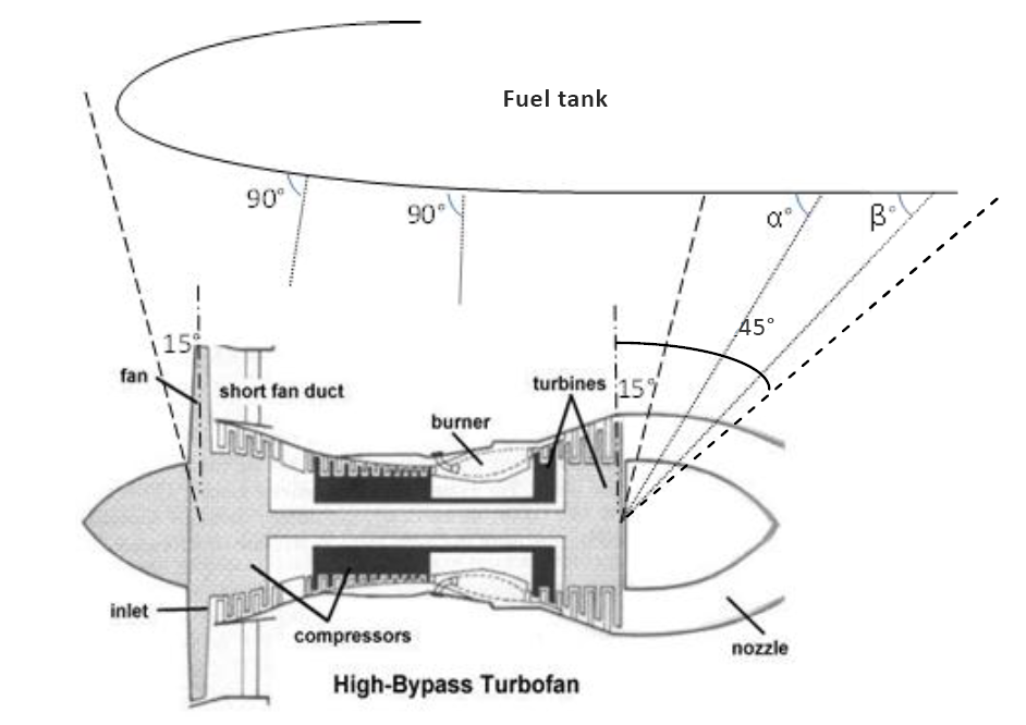
Note: α and β
angles are examples of possible angles between the fuel tank skin and the
debris trajectory at the impact.
Figure
1 — Cube impact angles

Figure
2 — Example of the ± 15-degree threat area representation
Note: The threat
area between – 15 and – 45 degrees is not represented.
(iii) APU
Debris — For small APU debris, the small fragment model as defined in AMC
20-128A applies. The impact should not create a hazardous fuel leak (as
defined in paragraph 3.a above).
Note: AMC 20-128A remains applicable to APU debris, other than small
APU fragments, threatening fuel tanks as described here, and also remains
applicable to all APU debris to other areas of the aircraft structures and
systems.
4. RESISTANCE TO FIRE
Fuel tank access covers meet the requirements of CS 25.963(e)(2) if they are fabricated from solid aluminium or titanium alloys, or steel. They also meet the above requirement if one of the following criteria is met.
a. The covers can withstand the test of AC 20-135, “Powerplant Installation and Propulsion System Component Fire Protection Test Methods, Standards, and Criteria”, issued 2/9/90, or ISO 2685-1992(E), “Aircraft Environment conditions and test procedures for airborne equipment - Resistance to fire in designated fire zones”, for a period of time at least as great as an equivalent aluminium alloy in dimensions appropriate for the purpose for which they are used.
b. The covers can withstand the test of AC 20-135, Powerplant Installation and Propulsion System Component Fire Protection Test Methods, Standards, and Criteria, issued 2/9/90, or ISO 2685-1992(E), Aircraft - Environment conditions and test procedures for airborne equipment - Resistance to fire in designated fire zones, for a period of time at least as great as the minimum thickness of the surrounding wing structure.
c. The covers can withstand the test of AC 20-135, Powerplant Installation and Propulsion System Component Fire Protection Test Methods, Standards, and Criteria, issued 2/9/90, or ISO 2685-1992(E), Aircraft - Environment conditions and test procedures for airborne equipment - Resistance to fire in designated fire zones, for a period of 5 minutes. The test cover should be installed in a test fixture representative of actual installation in the aeroplane. Credit may be allowed for fuel as a heat sink if covers will be protected by fuel during all likely conditions. The maximum amount of fuel that should be allowed during this test is the amount associated with reserve fuel. Also, the static fuel pressure head should be accounted for during the burn test. There should be no burn-through or distortion that would lead to fuel leakage at the end of the tests; although damage to the cover and seal is permissible.
[Amdt 25/3]
[Amdt 25/14]