ED Decision 2016/010/R
(See AMC 25.335)
The selected design airspeeds are equivalent airspeeds (EAS). Estimated values of VS0 and VS1 must be conservative.
(a) Design cruising speed, VC. For VC, the following apply:
(1) The minimum value of VC must be sufficiently greater than VB to provide for inadvertent speed increases likely to occur as a result of severe atmospheric turbulence.
(2) Except as provided in sub-paragraph 25.335(d)(2), VC may not be less than VB + 1·32 Uref (with Uref as specified in sub-paragraph 25.341(a)(5)(i). However, VC need not exceed the maximum speed in level flight at maximum continuous power for the corresponding altitude.
(3) At altitudes where VD is limited by Mach number, VC may be limited to a selected Mach number. (See CS 25.1505.)
(b) Design dive speed, VD. VD must be selected so that VC/MC is not greater than 0·8 VD/MD, or so that the minimum speed margin between VC/MC and VD/MD is the greater of the following values:
(1) (i) For aeroplanes not equipped with a high speed protection function: From an initial condition of stabilised flight at VC/MC, the aeroplane is upset, flown for 20 seconds along a flight path 7·5° below the initial path, and then pulled up at a load factor of 1·5 g (0·5 g acceleration increment). The speed increase occurring in this manoeuvre may be calculated if reliable or conservative aerodynamic data issued. Power as specified in CS 25.175(b)(1)(iv) is assumed until the pullup is initiated, at which time power reduction and the use of pilot controlled drag devices may be assumed;
(ii) For aeroplanes equipped with a high speed protection function: In lieu of subparagraph (b)(1)(i), the speed increase above VC/MC resulting from the greater of the following manoeuvres must be established:
(A) From an initial condition of stabilised flight at VC/MC, the aeroplane is upset so as to take up a new flight path 7.5° below the initial path. Control application, up to full authority, is made to try and maintain this new flight path. Twenty seconds after achieving the new flight path, manual recovery is made at a load factor of 1.5 g (0.5 g acceleration increment), or such greater load factor that is automatically applied by the system with the pilot’s pitch control neutral. The speed increase occurring in this manoeuvre may be calculated if reliable or conservative aerodynamic data is used. Power as specified in CS 25.175(b)(1)(iv) is assumed until recovery is made, at which time power reduction and the use of pilot controlled drag devices may be assumed.
(B) From a speed below VC/MC, with power to maintain stabilised level flight at this speed, the aeroplane is upset so as to accelerate through VC/MC at a flight path 15° below the initial path (or at the steepest nose down attitude that the system will permit with full control authority if less than 15°). Pilot controls may be in neutral position after reaching VC/MC and before recovery is initiated. Recovery may be initiated 3 seconds after operation of high speed, attitude, or other alerting system by application of a load factor of 1.5 g (0.5 g acceleration increment), or such greater load factor that is automatically applied by the system with the pilot’s pitch control neutral. Power may be reduced simultaneously. All other means of decelerating the aeroplane, the use of which is authorised up to the highest speed reached in the manoeuvre, may be used. The interval between successive pilot actions must not be less than 1 second (See AMC 25.335(b)(1)(ii)).
(2) The minimum speed margin must be enough to provide for atmospheric variations (such as horizontal gusts, and penetration of jet streams and cold fronts) and for instrument errors and airframe production variations. These factors may be considered on a probability basis. The margin at altitude where MC is limited by compressibility effects must not be less than 0.07M unless a lower margin is determined using a rational analysis that includes the effects of any automatic systems. In any case, the margin may not be reduced to less than 0.05M. (See AMC 25.335(b)(2))
(c) Design manoeuvring speed, VA. For VA, the following apply:
(1) VA may not be less than VS1 √n where –
(i) n is the limit positive manoeuvring load factor at VC; and
(ii) VS1 is the stalling speed with wing-flaps retracted.
(2) VA and VS must be evaluated at the design weight and altitude under consideration.
(3) VA need not be more than VC or the speed at which the positive CNmax curve intersects the positive manoeuvre load factor line, whichever is less.
(d) Design speed for maximum gust intensity, VB.
(1) VB may not be less than
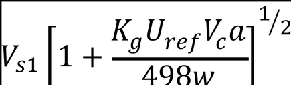
where –
Vsl = the 1-g stalling speed based on CNAmax with the flaps retracted at the particular weight under consideration;
CNAmax = the maximum aeroplane normal force coefficient;
Vc = design cruise speed (knots equivalent airspeed);
Uref = the reference gust velocity (feet per second equivalent airspeed) from CS 25.341(a)(5)(i);
w = average wing loading (pounds per square foot) at the particular weight under consideration.
Kg = 
µ = 
ρ = density of air (slugs/ft3);
c = mean geometric chord of the wing (feet);
g = acceleration due to gravity (ft/sec2);
a = slope of the aeroplane normal force coefficient curve, CNA per radian;
(2) At altitudes where Vc is limited by Mach number –
(i) VB may be chosen to provide an optimum margin between low and high speed buffet boundaries; and,
(ii) VB need not be greater than VC.
(e) Design wing-flap speeds, VF. For VF, the following apply:
(1) The design wing-flap speed for each wing-flap position (established in accordance with CS 25.697(a)) must be sufficiently greater than the operating speed recommended for the corresponding stage of flight (including balked landings) to allow for probable variations in control of airspeed and for transition from one wing-flap position to another.
(2) If an automatic wing-flap positioning or load limiting device is used, the speeds and corresponding wing-flap positions programmed or allowed by the device may be used.
(3) VF may not be less than –
(i) 1·6 VS1 with the wing-flaps in take-off position at maximum take-off weight;
(ii) 1·8 VS1 with the wing-flaps in approach position at maximum landing weight; and
(iii) 1·8 VS0 with the wing-flaps in landing position at maximum landing weight.
(f) Design drag device speeds, VDD. The selected design speed for each drag device must be sufficiently greater than the speed recommended for the operation of the device to allow for probable variations in speed control. For drag devices intended for use in high speed descents, VDD may not be less than VD. When an automatic drag device positioning or load limiting means is used, the speeds and corresponding drag device positions programmed or allowed by the automatic means must be used for design.
[Amdt 25/13]
[Amdt 25/18]