Part II – Airframe Ice Accretions
ED
Decision 2015/008/R
(a) Ice accretions - General. The most
critical ice accretion in terms of aeroplane performance and handling
qualities for each flight phase must be used to show compliance with the
applicable aeroplane performance and handling requirements in icing conditions
of subpart B of this part. Applicants must demonstrate that the full range of
atmospheric icing conditions specified in part I of this appendix have been
considered, including the mean effective drop diameter, liquid water content,
and temperature appropriate to the flight conditions (for example,
configuration, speed, angle-of-attack, and altitude). The ice accretions for
each flight phase are defined as follows:
(1) Take-off Ice
is the most critical ice accretion on unprotected surfaces, and any ice
accretion on the protected surfaces appropriate to normal ice protection
system operation, occurring between the end of the take-off distance and 122 m
(400 ft) above the take-off surface, assuming accretion starts at the end of
the take-off distance in the take-off maximum icing conditions of Part I,
paragraph (c) of this Appendix.
(2) Final Take-off Ice
is the most critical ice accretion on unprotected surfaces, and any ice
accretion on the protected surfaces appropriate to normal ice protection
system operation, between 122 m (400 ft) and either 457 m (1500 ft) above the
take-off surface, or the height at which the transition from the take-off to
the en route configuration is completed and VFTO is reached,
whichever is higher. Ice accretion is assumed to start at the end of the
take-off distance in the take-off maximum icing conditions of Part I,
paragraph (c) of this Appendix.
(3) En-route Ice
is the critical ice accretion on the unprotected surfaces, and any ice
accretion on the protected surfaces appropriate to normal ice protection
system operation, during the en-route phase.
(4) Holding Ice
is the critical ice accretion on the unprotected surfaces, and any ice
accretion on the protected surfaces appropriate to normal ice protection
system operation, during the holding flight phase.
(5) Approach ice
is the critical ice accretion on the unprotected surfaces, and any ice
accretion on the protected surfaces appropriate to normal ice protection
system operation following exit from the holding flight phase and transition
to the most critical approach configuration.
(6) Landing ice
is the critical ice accretion on the unprotected surfaces, and any ice
accretion on the protected surfaces appropriate to normal ice protection
system operation following exit from the approach flight phase and transition
to the final landing configuration.
(b) In order to reduce the number of ice
accretions to be considered when demonstrating compliance with the
requirements of paragraph CS 25.21(g), any of the ice accretions defined
in sub-paragraph (a) of this section may be used for any other flight phase if
it is shown to be more critical than the specific ice accretion defined for
that flight phase. Configuration differences and their effects on ice
accretions must be taken into account.
(c) The ice accretion that has the most
adverse effect on handling characteristics may be used for aeroplane
performance tests provided any difference in performance is conservatively
taken into account.
(d) For both unprotected and protected parts,
the ice accretion for the takeoff phase may be determined by calculation,
assuming the takeoff maximum icing conditions defined in appendix C, and
assuming that:
(1) Airfoils, control surfaces and, if
applicable, propellers are free from frost, snow, or ice at the start of the
take-off;
(2) The ice accretion starts at the end of the
take-off distance;
(3) The critical ratio of
thrust/power-to-weight;
(4) Failure of the critical engine occurs at VEF;
and
(5) Crew activation of the ice protection
system is in accordance with a normal operating procedure provided in the
Aeroplane Flight Manual, except that after beginning the takeoff roll, it must
be assumed that the crew takes no action to activate the ice protection system
until the airplane is at least 122 m (400 ft) above the takeoff surface.
(e) The ice accretion before the ice
protection system has been activated and is performing its intended function
is the critical ice accretion formed on the unprotected and normally protected
surfaces before activation and effective operation of the ice protection
system in continuous maximum atmospheric icing conditions. This ice accretion
only applies in showing compliance to CS 25.143(j), 25.207(h)
and 25.207(i).
[Amdt
25/3]
[Amdt
25/7]
[Amdt
25/16]
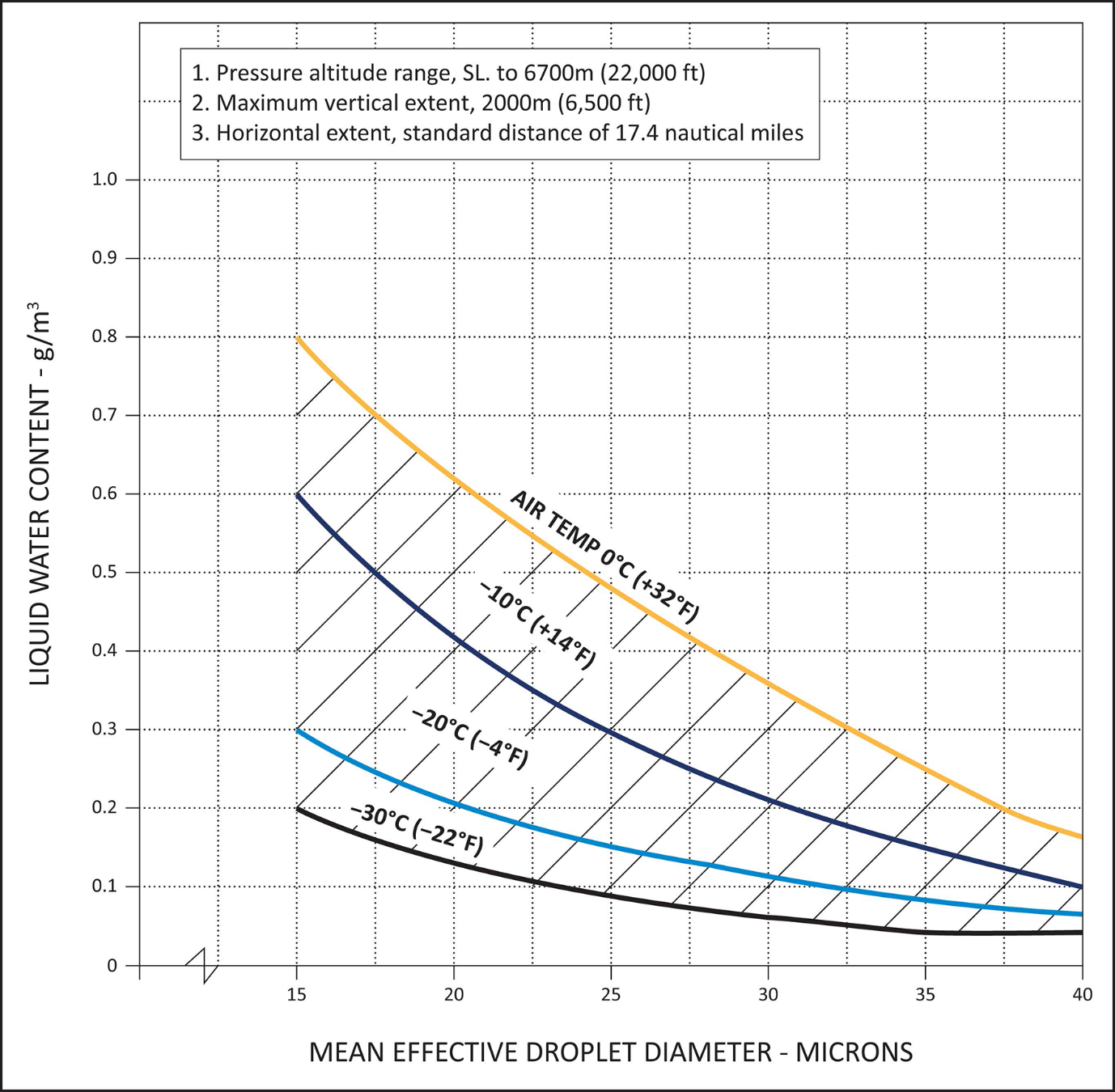
FIGURE 1
CONTINUOUS MAXIMUM (STRATIFORM CLOUDS) ATMOSPHERIC
ICING CONDITIONS
LIQUID WATER CONTENT VS MEAN EFFECTIVE DROP DIAMETER
Source of data – NACA TN No. 1855, Class III –M,
Continuous Maximum.
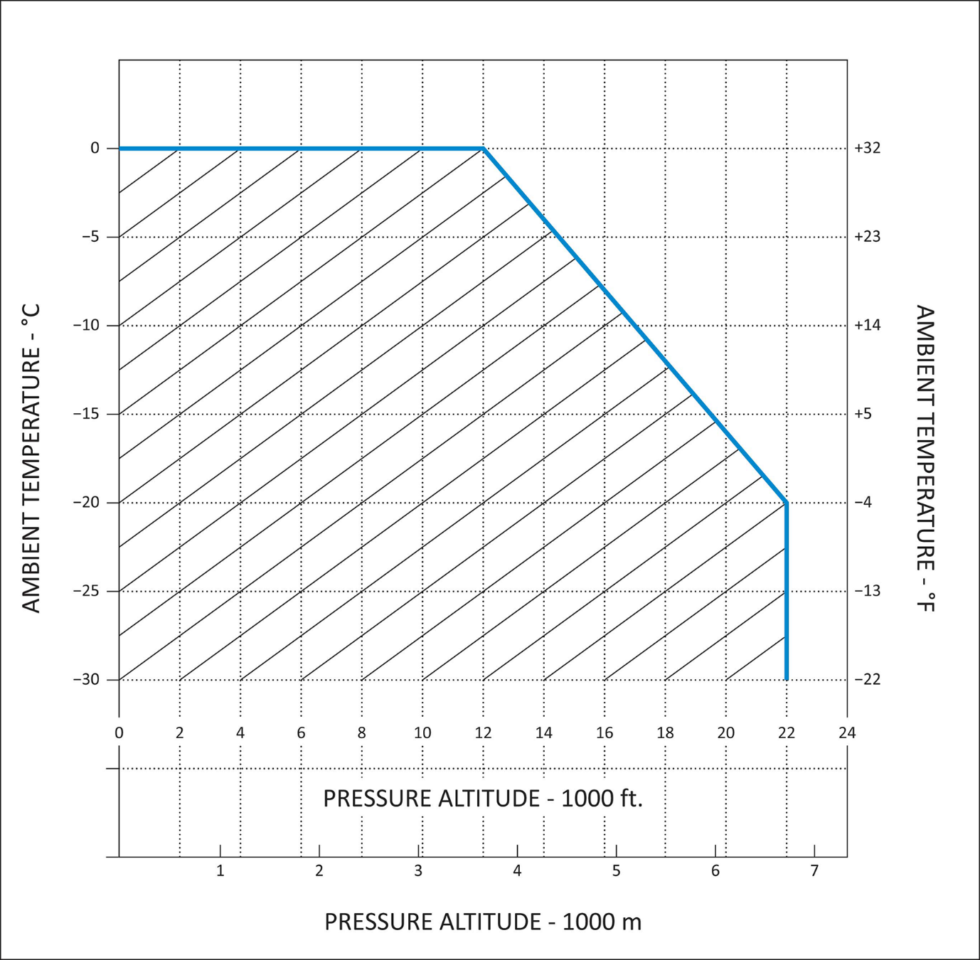
FIGURE 2
CONTINUOUS MAXIMUM (STRATIFORM CLOUDS) ATMOSPHERIC
ICING CONDITIONS
AMBIENT TEMPERATURE VS PRESSURE ALTITUDE
Source of data – NACA TN No. 2569.
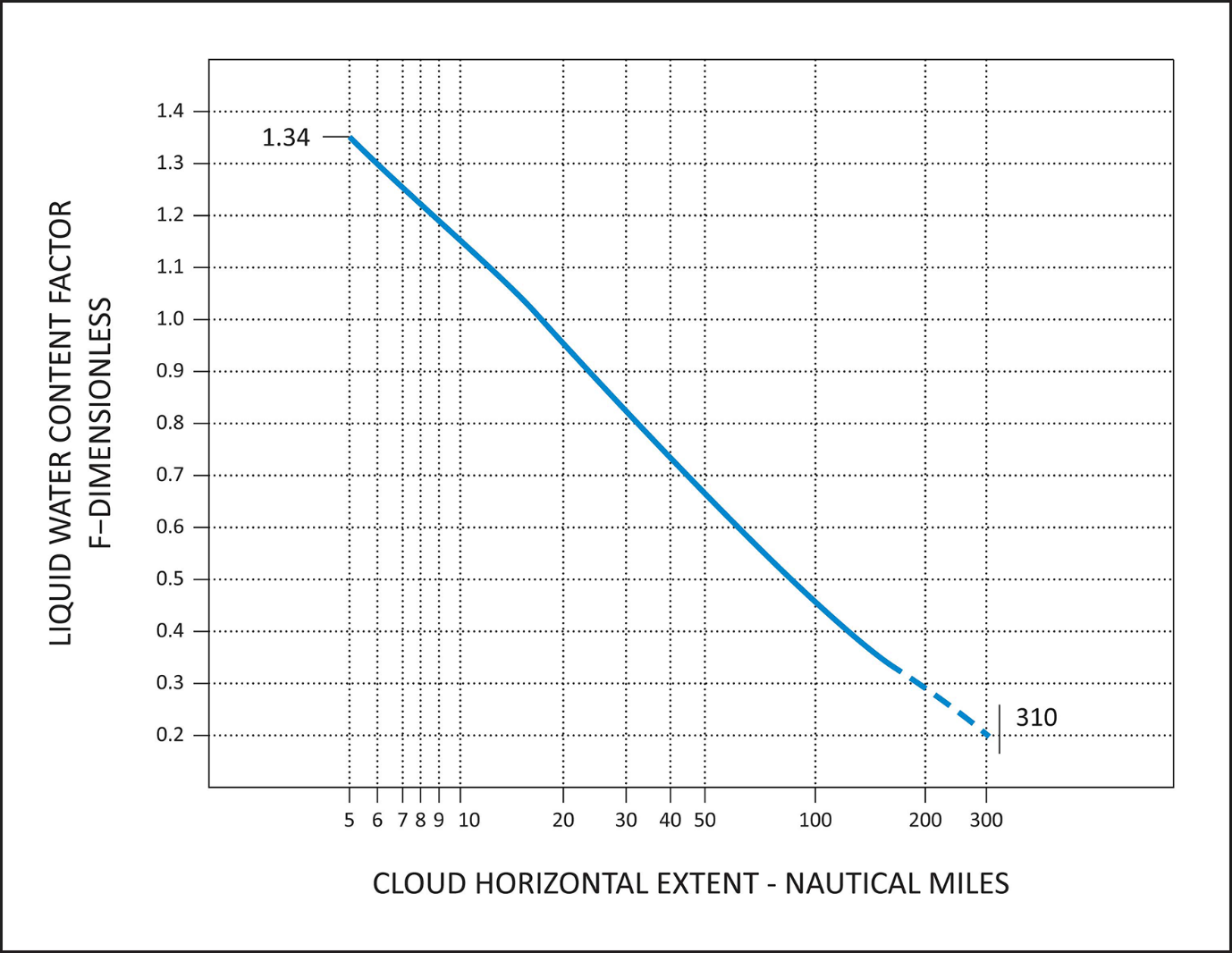
FIGURE 3
CONTINUOUS MAXIMUM (STRATIFORM CLOUDS) ATMOSPHERIC
ICING CONDITIONS
LIQUID WATER CONTENT FACTOR VS CLOUD HORIZONTAL
DISTANCE
Source of data – NACA TN No. 2738.
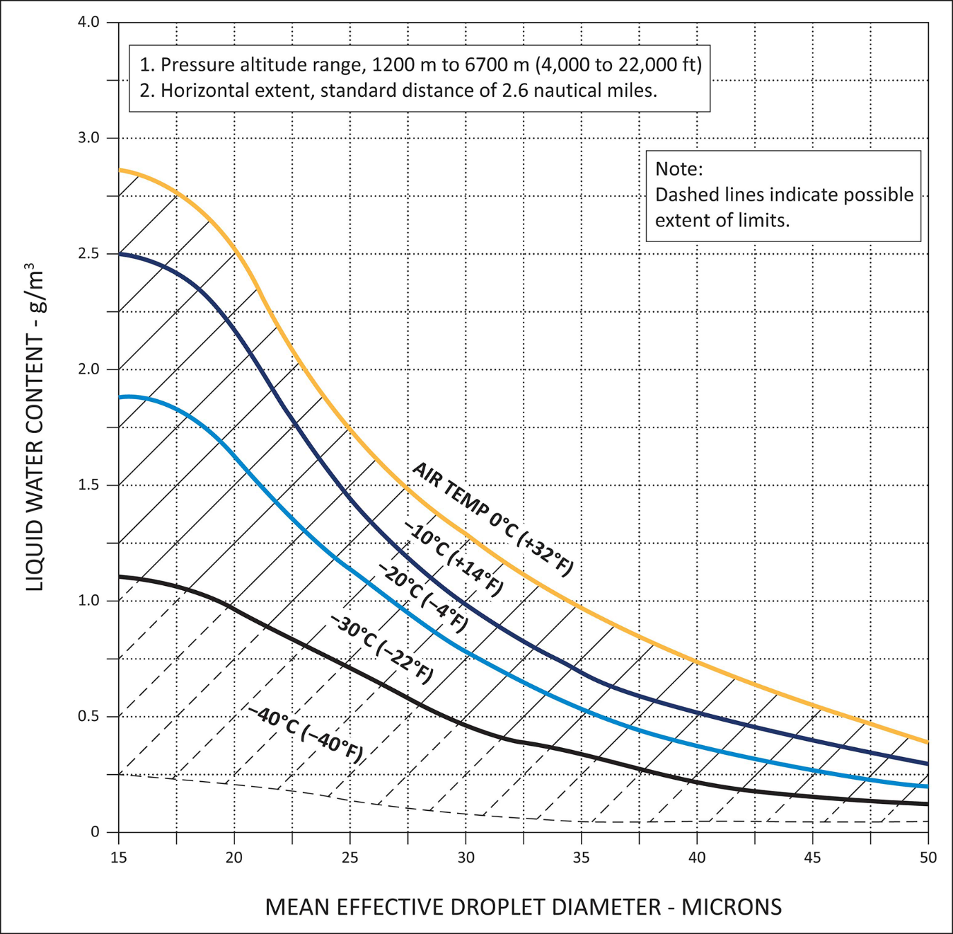
FIGURE 4
INTERMITTENT MAXIMUM (CUMULIFORM CLOUDS) ATMOSPHERIC
ICING CONDITIONS
LIQUID WATER CONTENT VS MEAN EFFECTIVE DROP DIAMETER
Source of data – NACA TN No. 1855, Class II – M,
Intermittent Maximum
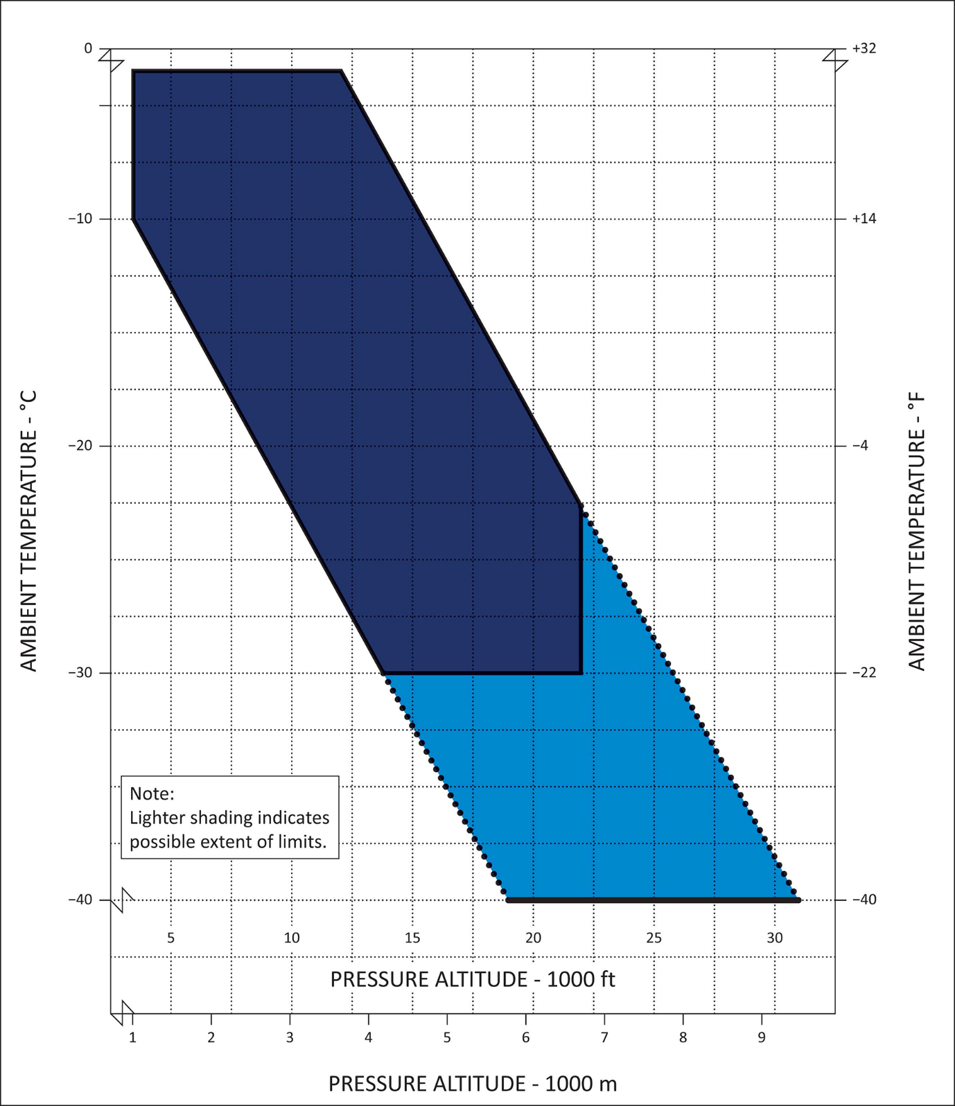
FIGURE 5
INTERMITTENT MAXIMUM (CUMULIFORM CLOUDS) ATMOSPHERIC
ICING CONDITIONS
AMBIENT TEMPERATURE VS PRESSURE ALTITUDE
Source of data – NACA TN No. 2569.
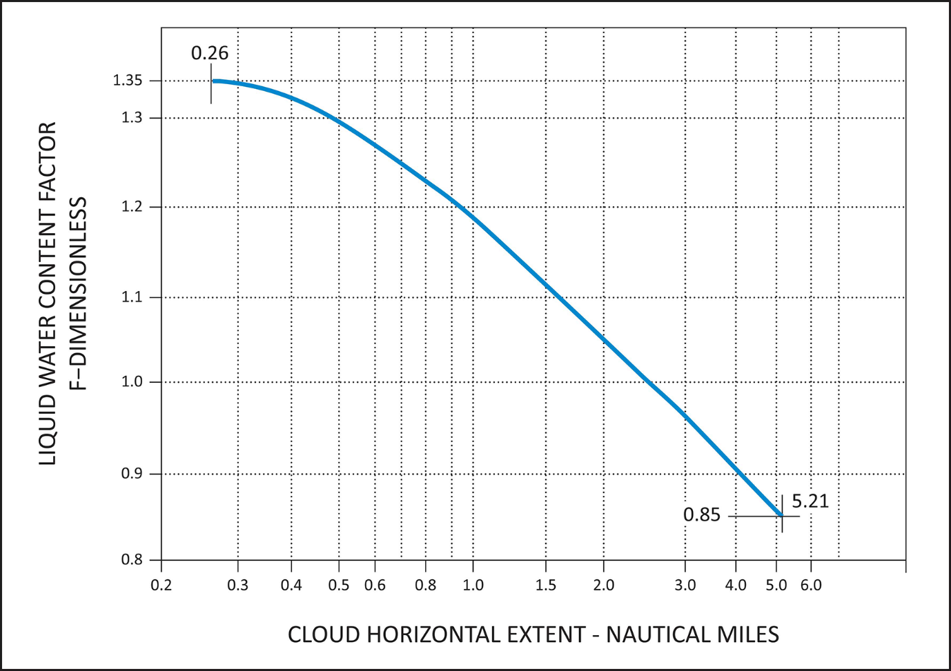
FIGURE 6
INTERMITTENT MAXIMUM (CUMULIFORM CLOUDS) ATMOSPHERIC
ICING CONDITIONS
VARIATION OF LIQUID WATER CONTENT FACTOR WITH CLOUD
HORIZONTAL EXTENT
Source of data – NACA TN No. 2738.