Appendix D — RF leg
demonstration templates
ED Decision 2019/011/R
(1) Applicants must demonstrate the aircraft’s capability to perform all types of RF legs that can be published on instrument procedures as per the procedure design criteria. Appendix D provides templates that are an acceptable method to demonstrate an aircraft’s capability to perform RF legs. Applicants may use engineering simulations and/or aircraft for the flight test demonstrations. The templates depict the various RF legs that procedure designers may use when constructing actual initial, intermediate, missed approach, or final approach segments for RNP approaches along with SIDs and STARs. Applicants may use the templates to create one or more approach procedures at the desired aerodrome for flight test demonstration purposes in visual meteorological conditions only. The intent of such demonstrations is to streamline the airworthiness approval for conducting RF legs.
(2) The demonstration procedures need to include the depicted RF leg types shown in AppD-2. To increase flight test efficiency, it is acceptable for applicants to link the individual RF legs that are depicted in the figures by using straight segments to create ‘mega procedures’ for demonstrating the aircraft’s capability. However, the reflex curve legs (‘S-turns’) and decreasing radius turns must not have a straight segment between the path terminators (see Figure 1 below for an example). The point is to demonstrate that the aircraft is capable of flying the various types of turns including turns of minimum radius.
Note: Figure 1 is only an
example and is not intended as the only possible combination for creating
efficient flight profiles.
4000 5200 5400 5600 4400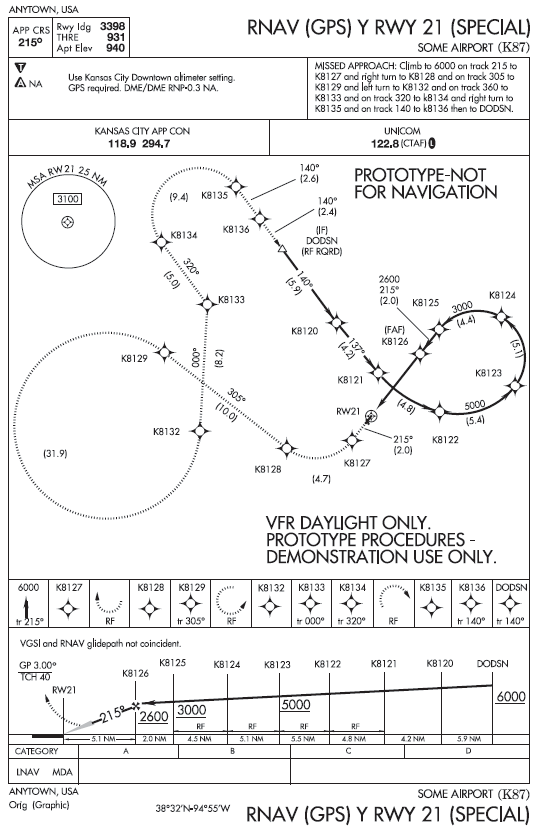
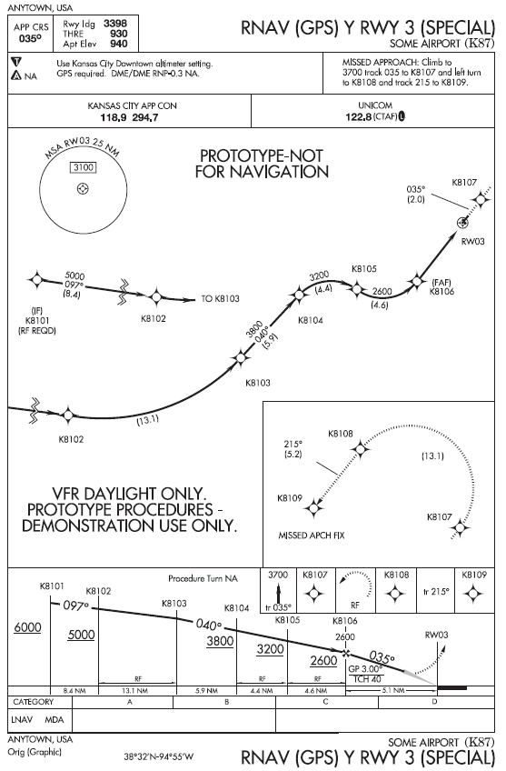
Figure 1: Example procedure
profiles
(4) AppD-2 provides a basic description,
illustration, and waypoint information for the RF legs.
A ‘test guide’ in AppD-3 lists a
recommended testing regimen and considerations for test conduct, but the
applicant can tailor the test regimen as needed.
AppD-2 — Description of test procedures
Each of the procedures is described in this section along with an image for illustration.
AppD-2.1 — Departures
(1) Design criteria for departures are currently being developed. Subsequently, two procedures were designed using known criteria in addition to criteria features that are likely to be incorporated. One of the procedures mimics a conventional design at Boston Logan International Airport that has proven difficult for some high-performance aircraft to use. Due to environmental restrictions on the ground track, the previous conventional procedure incorporates a series of short track-to-fix (TF) legs that, when viewed from a larger perspective, ‘looks’ like a series of RF legs when considering that each of the waypoints are ‘fly-by’. However, in the conventional format, some FMSs have difficulty with the short leg segments and, therefore, annunciate an inability to capture a subsequent leg. The resolution to this issue is the RF leg or a series of RF legs that ensure conformance to the desired ground path. The ‘Alpha departure’ shown in Figure 2 incorporates an RF leg shortly after take-off followed by a straight climbing segment to a series of two back-to-back RF legs with reducing radii. Waypoint information is shown in Table 1.
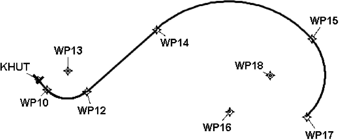
Figure
2: Alpha departure
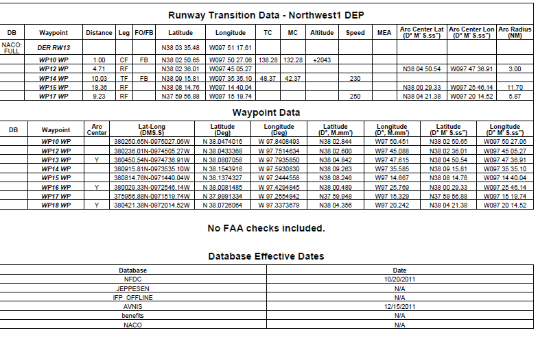
Table
1: Alpha departure
waypoints
(2) The ‘Bravo departure’ shown in Figure 3 consists of an RF leg shortly after take-off followed by a brief straight segment, then two back-to-back RF legs with a turn direction reversal. The turn radii also vary as the aircraft climbs and increases performance. Waypoint information is shown in Table 2.
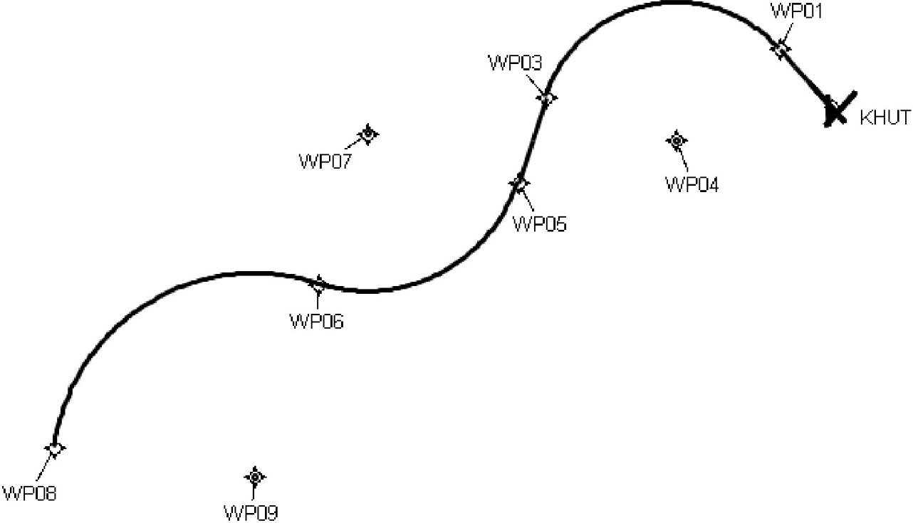
Figure
3: Bravo departure
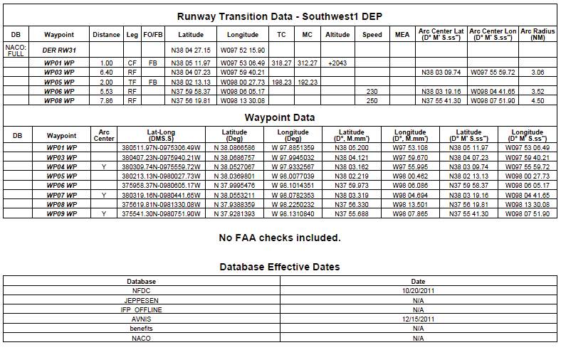
Table 2: Bravo departure waypoints
AppD-2.2 — Arrival
(1) A single arrival was designed which is similar to a previously studied design at Fargo, North Dakota, USA. As the aircraft descends and decelerates, it follows a path that consists of a series of RF legs with a reversal of the turn direction after the first turn. The second directional turn consists of two back-to-back RF legs with decreasing radii. The arrival is shown in Figure 4 and waypoint information is shown in Table 3.
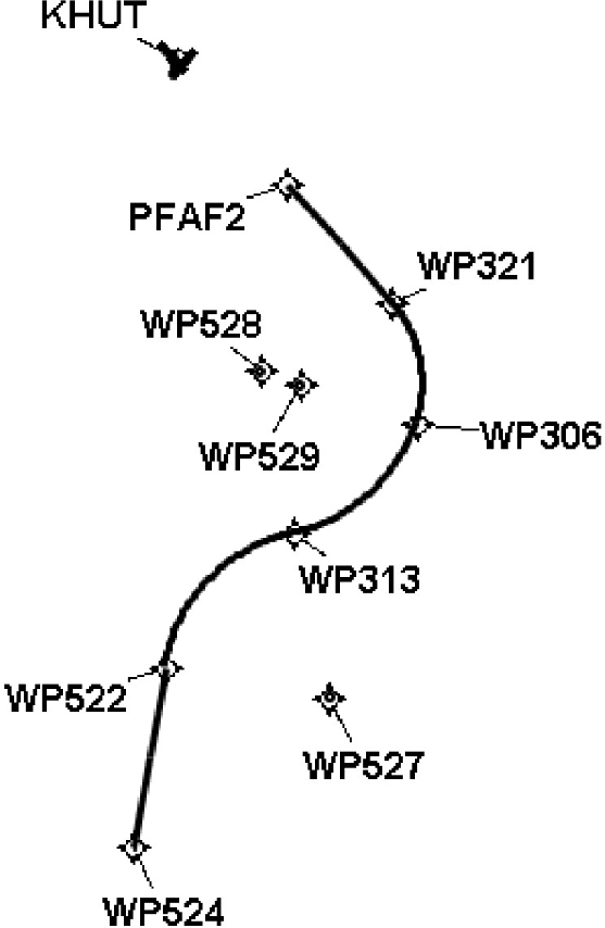
Figure
4: Arrival
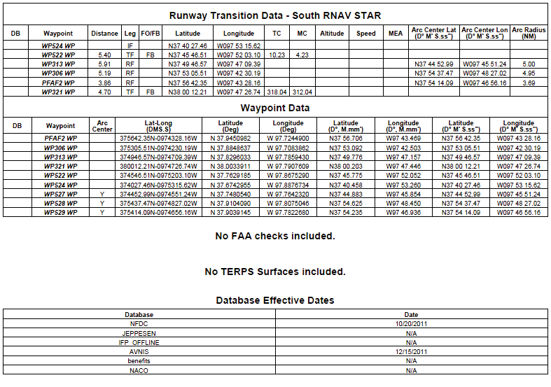
Table
3: Arrival waypoints
AppC-2.3 — Approaches
(1) Three approaches are provided to assess avionics guidance capability through a series of RF leg approach designs. These templates are acceptable for demonstrating the aircraft’s capability to perform both RNP AR and standard RNP APCH approach procedures.
(2) As shown in Figure 5, Approach 1 is a teardrop procedure that incorporates a descending RF right turn to final, rolling out at the final approach fix. Note that there is no straight segment 2 NM prior to the final approach fix which will be stressing for RNP APCH final approach guidance due to the reduced scaling transition from terminal mode to approach mode. This path requires the aircraft to descend, decelerate, and then configure for landing all during the RF leg. The missed approach also contains an RF leg en route to the missed approach hold. Waypoint information is shown in Table 4 and vertical error budget information is shown in Table 5.
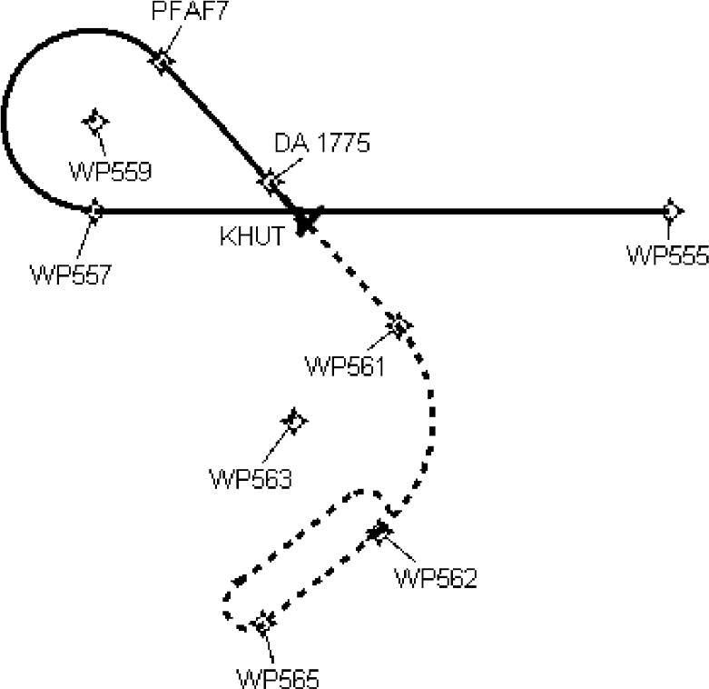
Figure 5: Approach
1
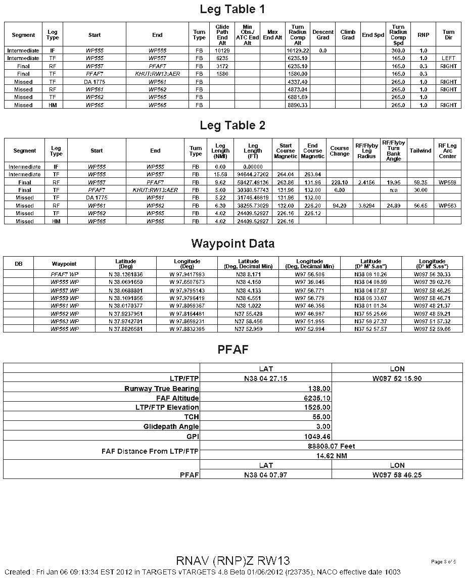
Table 4: Approach 1
waypoint information
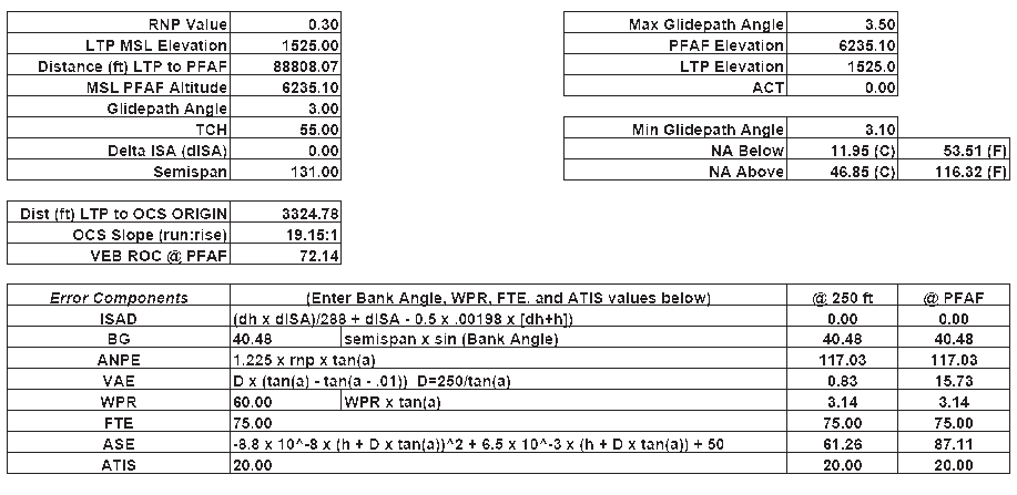
Table
5: Approach 1 vertical
error budget (VEB)
(3) Approach 2, as shown in Figure 6, is also a descending right turn to final but has a series of four RF legs with differing radii. Similar to Approach 1 in Figure 5, this path will require the aircraft to descend and decelerate during the RF leg. Waypoint information is shown in Table 6 and vertical error budget information is included in Table 7.
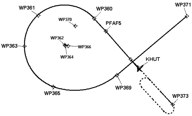
Figure
6: Approach 2
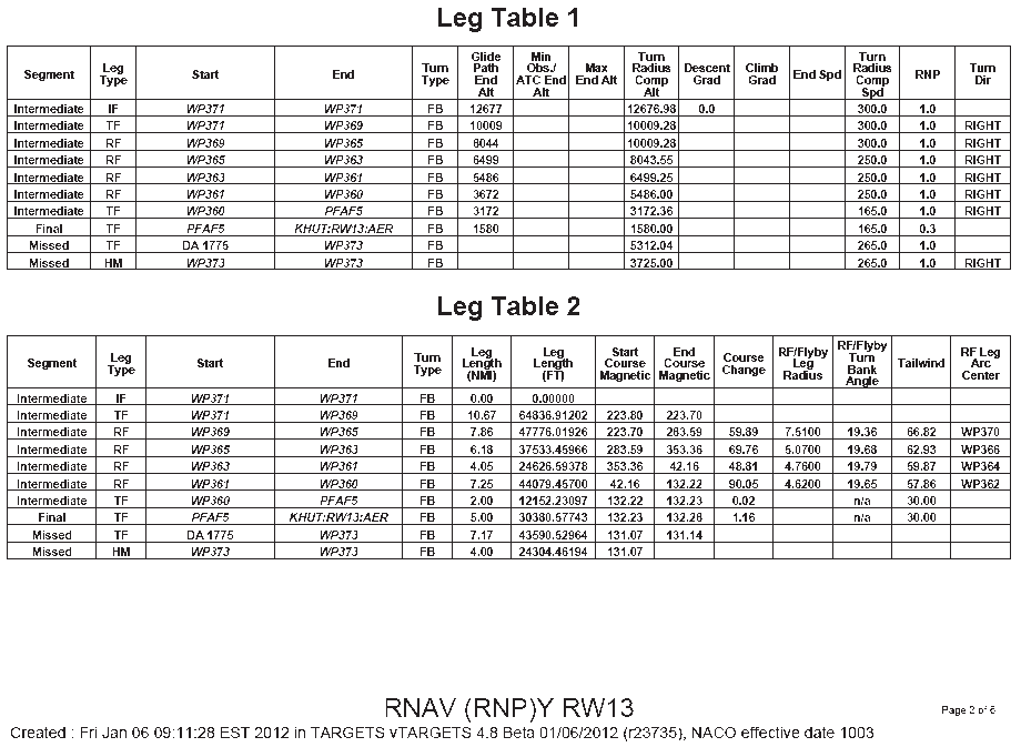
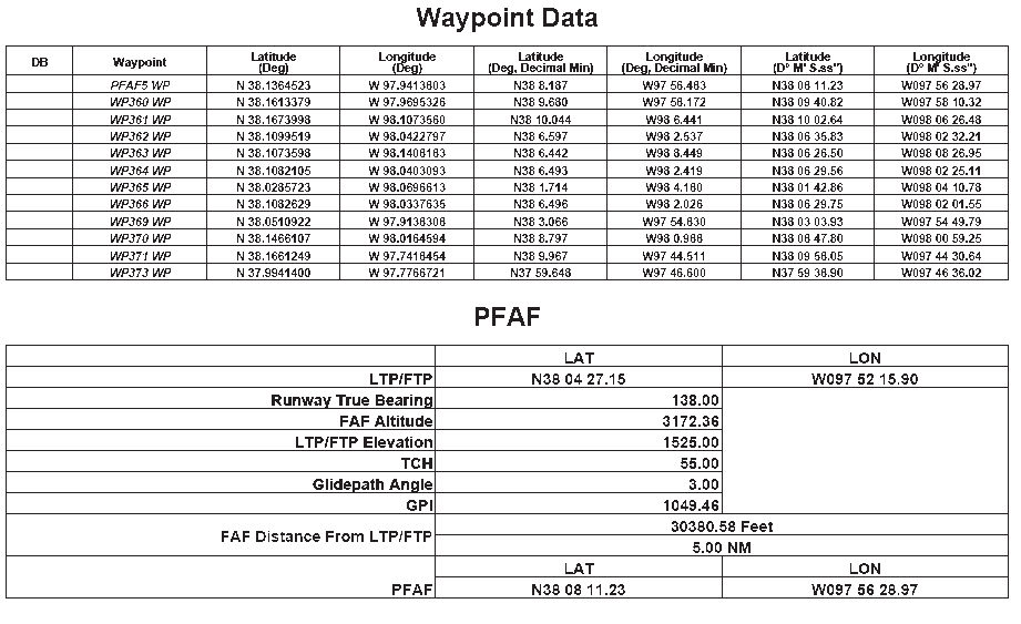
Table 6:
Approach 2 waypoints
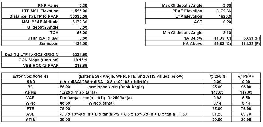
Table
7: Approach 2 vertical
error budget (VEB)
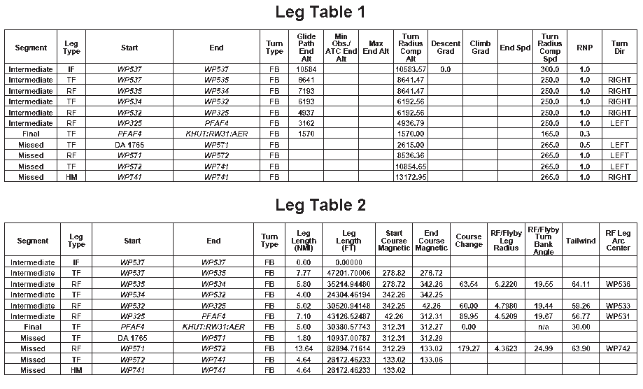
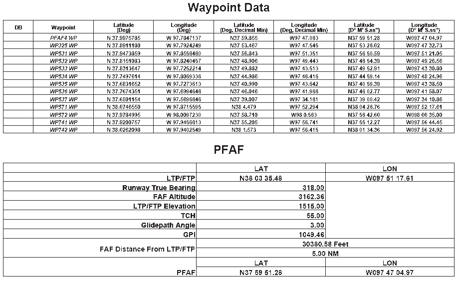
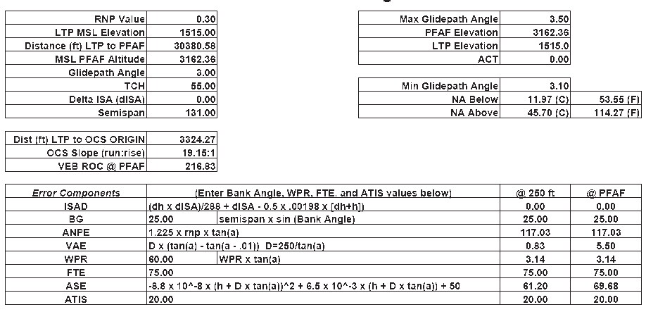
(4) Approach 3 is shown in Figure 7. This procedure uses an RF leg early in the procedure followed by a brief straight segment, then two back-to-back RF legs with a turn direction reversal. The second RF leg terminates at the final approach fix. As on the other approaches, the aircraft will be required to descend, decelerate, and configure for landing during the series of RF legs. The missed approach also includes an RF leg to the missed approach hold. Waypoint information is shown in Table 8 and vertical error budget information is included in Table 9.
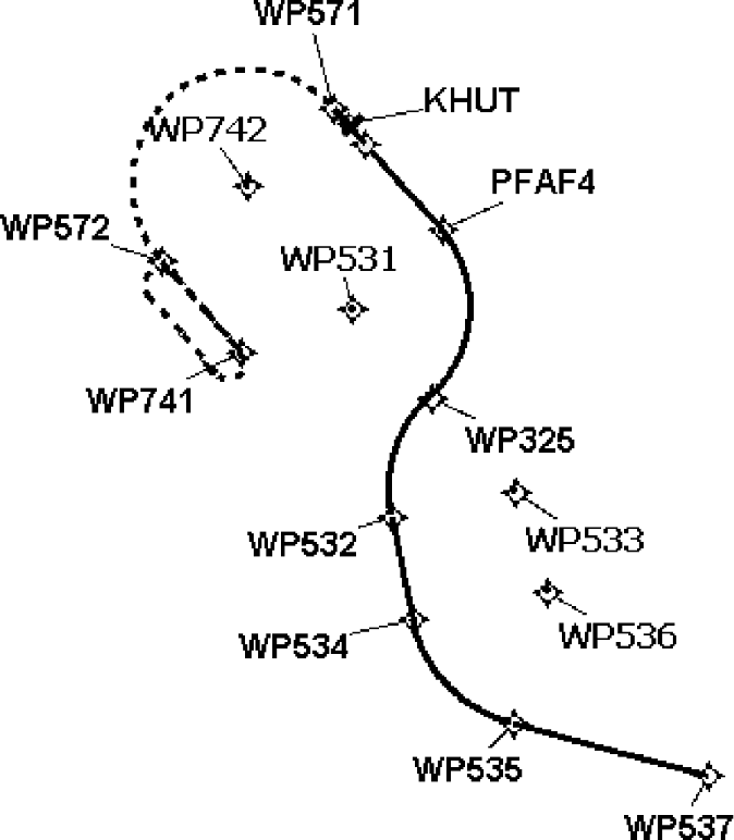
Figure 7:
Approach 3
Table
8: Approach 3 waypoints
Table
9: Approach 3 vertical
error budget (VEB)
(1) AppD-3 provides guidance that may be used to conduct development and/or airworthiness RF leg testing for new equipment hardware/software, or updates to existing equipment hardware/software. The guidance is designed to be used together with the templates described in AppD-2 to create .‘FOR TEST ONLY’ terminal area instrument procedures (departures, arrivals, and approaches). The intent of this regimen is to provide a set of rigorous instrument procedures that the applicant can use to demonstrate that the RF leg airworthiness approval criteria are met.
(2) The test instrument procedures are designed and located at an aerodrome with an elevation of approximately 1 500-ft MSL. The waypoint and navigation leg data is provided so that the procedures can be ‘translated’ to another location suitable to the applicant. However, the new aerodrome elevation should be within the range of 1 000–2 000-ft MSL to ensure that the designed turn radii and bank angles do not change significantly (see AppD-1). The applicant will be required to obtain a navigation database for their respective navigation system that contains the test procedures.
(3) The information in the following paragraphs describes test conditions such as generic aircraft performance parameters, desired atmospheric conditions, and considerations to assist the applicant with creating a detailed test plan. Applicants are encouraged to use these recommended guidelines. However, amendments may be made as required to accommodate unique equipment designs, test environment, testing methods, or other considerations.
AppD-3.1 — Initial set-up
(1) Configure the aircraft for individual trials using two gross weight conditions:
(a) nominal heavy weight resulting in lower accelerations to climb speed and higher speeds on approach;
(b) nominal light weight resulting in higher accelerations to climb speed and lower speeds on approach.
(2) The test should be performed in representative operational conditions in terms of speeds, flap, and gear settings, etc.
(3) Verify that a navigation database with the ‘FOR TEST ONLY’ terminal procedures is loaded in the RNP system.
(4) Verify that desired data parameters will be recorded (if data recording capability is available).
Note: In addition to the desired data parameters, the lateral path definition (desired path) and lateral path ‘cross-track error’ (distance from the path’s centre line) should be included in the recorded data parameters to monitor/review path maintenance performance.
(5) Configure the simulation, if practical, for trials using two atmospheric conditions:
(a) standard day, with standard lapse rate;
(b) 35 °C outside air temperature, with standard lapse rate.
(6) If practical, simulated wind direction should be set to a tailwind for each turn entry. Below 2 000-ft AGL, the wind velocity should be fixed at 30 kt. At 2 000-ft AGL and above, the wind velocity in knots (VKTW) should be calculated as a function of the altitude in feet (A) in accordance with the formula:

If impractical (i.e. when the simulator cannot model variable winds and various levels), select the wind direction and velocity that most effectively simulates the worst-case tailwind for the procedure.
AppD-3.2 — Airborne test conditions
(1) Record aircraft configuration:
(a) verify that the simulation is ‘conformed’ with correct avionics hardware and software;
(b) record aircraft performance parameters (gross weight, etc.);
(c) record aircraft configuration and changes to the configuration (flap, gear, and thrust setting, etc.).
(2) Select the procedure to be tested, load the procedure into the route of flight, and verify the procedure is in the active route.
(3) Ensure the correct RNP values correspond to the appropriate value for the respective route/procedure segment.
(4) Engage lateral and vertical path guidance where applicable.
(5) Engage autopilot/flight director (as soon as practical after take-off) and verify the autopilot/flight director is providing guidance to the lateral path.
(6) Fly the programmed route and observe that the lateral cross-track deviation does not exceed the FTE for the respective RNP level as follows:
|
RNP |
FTE |
|
1.0 |
0.5 NM |
|
0.3 |
0.25 NM with flight director /
0.125 NM with autopilot |
|
< 0.3 |
Agreed allowable FTE value to
achieve TSE ≤ 1 × RNP value |
Table 10: FTE value versus
RNP value
(7) Perform steps (1) through (6) for each appropriate aircraft gross weight configuration and for each test procedure.