Part IV – Test Method to Determine the Heat Release Rate from Cabin
Materials Exposed to Radiant Heat
ED Decision 2016/010/R
(See AMC to Appendix F, Part IV)
(a) Summary of Method
(1) The specimen to be tested is injected into an environmental chamber through which a constant flow of air passes. The specimen’s exposure is determined by a radiant heat source adjusted to produce the desired total heat flux on the specimen of 3·5 Watts/cm2, using a calibrated calorimeter. The specimen is tested so that the exposed surface is vertical. Combustion is initiated by piloted ignition. The combustion products leaving the chamber are monitored in order to calculate the release rate of heat.
(b) Apparatus. The Ohio State University (OSU) rate of heat release apparatus as described below, is used. This is a modified version of the rate of heat release apparatus standardised by the American Society of Testing and Materials (ASTM), ASTM E-906.
(1) This apparatus is shown in Figure 1. All exterior surfaces of the apparatus, except the holding chamber, shall be insulated with 25 mm thick, low density, high-temperature, fibreglass board insulation. A gasketed door through which the sample injection rod slides forms an airtight closure on the specimen hold chamber.
(2) Thermopile. The temperature difference between the air entering the environmental chamber and that leaving is monitored by a thermopile having five hot and five cold, 24 gauge Chromel-Alumel junctions. The hot junctions are spaced across the top of the exhaust stack 10 mm below the top of the chimney. One thermocouple is located in the geometric centre; with the other four located 30 mm from the centre along the diagonal toward each of the corners (Figure 5). The cold junctions are located in the pan below the lower air distribution plate (see sub-paragraph (b)(4)). Thermopile hot junctions must be cleared of soot deposits as needed to maintain the calibrated sensitivity.
(3) Radiation Source. A radiant heat source for generating a flux up to 100 kW/m2, using four silicon carbide elements, Type LL, 50·8 cm (20 inches) long by 15·8 mm (0·625 inch) O.D., nominal resistance 1·4 ohms, is shown in Figures 2A and 2B. The silicon carbide elements are mounted in the stainless steel panel box by inserting them through 15·9 mm holes in 0·8 mm thick ceramic fibreboard. Location of the holes in the pads and stainless steel cover plates are shown in Figure 2B. The diamond shaped mask of 19-gauge stainless steel is added to provide uniform heat flux over the area occupied by the 150 by 150 mm vertical sample.
(4) Air Distribution System. The air entering the environmental chamber is distributed by a 6·3 mm thick aluminium plate having eight, No. 4 drill holes, 51 mm from sides on 102 mm centres, mounted at the base of the environmental chamber. A second plate of 18-gauge steel having 120, evenly spaced, No. 28 drill holes is mounted 150 mm above the aluminium plate. A well-regulated air supply is required. The air supply manifold at the base of the pyramidal section has 48, evenly spaced, No. 26 drill holes located 10 mm from the inner edge of the manifold so that 0·03 m3/second of air flows between the pyramidal sections and 0·01 m3/second flows through the environmental chamber when total air flow to apparatus is controlled at 0·04 m3/second.
(5) Exhaust Stack. An exhaust stack, 133 mm by 70 mm in cross section, and 254 mm long, fabricated from 28-gauge stainless steel, is mounted on the outlet of the pyramidal section. A 25 mm by 76 mm plate of 31-gauge stainless steel is centred inside the stack, perpendicular to the airflow, 75 mm above the base of the stack.
(6) Specimen Holders. The 150 mm x 150 mm specimen is tested in a vertical orientation. The holder (Figure 3) is provided with a specimen holder frame, which touches the specimen (which is wrapped with aluminium foil as required by sub-paragraph (d)(3)) along only the 6 mm perimeter, and a “V” shaped spring to hold the assembly together. A detachable 12 mm x 12 mm x 150 mm drip pan and two 0.51 mm (0·020 inch) stainless steel wires (as shown in Figure 3) should be used for testing of materials prone to melting and dripping. The positioning of the spring and frame may be changed to accommodate different specimen thicknesses by inserting the retaining rod in different holes on the specimen holder.
Since the radiation shield described in ASTM E-906 is not used, a guide pin is added to the injection mechanism. This fits into a slotted metal plate on the injection mechanism outside of the holding chamber and can be used to provide accurate positioning of the specimen face after injection. The front surface of the specimen shall be 100 mm from the closed radiation doors after injection.
The specimen holder clips onto the mounted bracket (Figure 3). The mounting bracket is attached to the injection rod by three screws, which pass through a wide area washer welded onto a 13 mm nut. The end of the injection rod is threaded to screw into the nut and a 5.1 mm thick wide area washer is held between two 13 mm nuts which are adjusted to tightly cover the hole in the radiation doors through which the injection rod or calibration calorimeter pass.
(7) Calorimeter. A total-flux type calorimeter must be mounted in the centre of a 13 mm Kaowool “M” board inserted in the sample holder must be used to measure the total heat flux. The calorimeter must have a view angle of 180° and be calibrated for incident flux. The calorimeter calibration must be acceptable to the Agency.
(8) Pilot-Flame Positions. Pilot ignition of the specimen must be accomplished by simultaneously exposing the specimen to a lower pilot burner and an upper pilot burner, as described in sub-paragraphs (b)(8)(i) and (b)(8)(ii), respectively. The pilot burners must remain lighted for the entire 5-minute duration of the test.
(i) Lower Pilot Burner. The pilot-flame tubing must be 6·3 mm O.D., 0·8 mm wall, stainless steel tubing. A mixture of 120 cm3/min. of methane and 850 cm3/min. of air must be fed to the lower pilot flame burner. The normal position of the end of the pilot burner tubing is 10 mm from and perpendicular to the exposed vertical surface of the specimen. The centreline at the outlet of the burner tubing must intersect the vertical centreline of the sample at a point 5 mm above the lower exposed edge of the specimen.
(ii) Upper Pilot Burner. The pilot burner must be a straight length of 6·3 mm O.D., 0·8 mm wall, stainless steel tubing 360 mm long. One end of the tubing shall be closed, and three No. 40 drill holes shall be drilled into the tubing, 60 mm apart, for gas ports, all radiating in the same direction. The first hole must be 5 mm from the closed end of the tubing. The tube is inserted into the environmental chamber through a 6·6 mm hole drilled 10 mm above the upper edge of the window frame. The tube is supported and positioned by an adjustable “Z” shaped support mounted outside the environmental chamber, above the viewing window. The tube is positioned above and 20 mm behind the exposed upper edge of the specimen. The middle hole must be in the vertical plane perpendicular to the exposed surface of the specimen, which passes through its vertical centreline and must be pointed toward the radiation source. The gas supplied to the burner must be methane adjusted to produce flame lengths of 25 mm.
(c) Calibration of Equipment
(1) Heat Release Rate. A burner as shown in Figure 4 must be placed over the end of the lower pilot flame tubing using a gas-tight connection. The flow of gas to the pilot flame must be at least 99% methane and must be accurately metered. Prior to usage, the wet test meter is properly levelled and filled with distilled water to the tip of the internal pointer while no gas is flowing. Ambient temperature and pressure of the water, are based on the internal wet test meter temperature. A baseline flow rate of approximately 1 litre/min. is set and increased to higher preset flows of 4, 6, 8, 6 and 4 litres/min. The rate is determined by using a stopwatch to time a complete revolution of the west test meter for both the baseline and higher flow, with the flow returned to baseline before changing to the next higher flow. The thermopile baseline voltage is measured. The gas flow to the burner must be increased to the higher preset flow and allowed to burn for 2·0 minutes, and the thermopile voltage must be measured. The sequence is repeated until all five values have been determined. The average of the five values must be used as the calibration factor. The procedure must be repeated if the percent relative standard deviation is greater than 5%. Calculations are shown in paragraph (f).
(2) Flux Uniformity. Uniformity of flux over the specimen must be checked periodically and after each heating element change to determine if it is within acceptable limits of ± 5%.
(d) Sample Preparation
(1) The standard size for vertically mounted specimens is 150 x 150 mm with thicknesses up to 45 mm.
(2) Conditioning. Specimens must be conditioned as described in Part 1 of this Appendix.
(3) Mounting. Only one surface of a specimen will be exposed during a test. A single layer of 0·025 mm aluminium foil is wrapped tightly on all unexposed sides.
(e) Procedure
(1) The power supply to the radiant panel is set to produce a radiant flux of 3·5 Watts/cm2. The flux is measured at the point, which the centre of the specimen surface will occupy when positioned for test. The radiant flux is measured after the airflow through the equipment is adjusted to the desired rate. The sample should be tested in its end use thickness.
(2) The pilot flames are lighted and their position, as described in sub-paragraph (b)(8), is checked.
(3) The airflow to the equipment is set at 0·04 ± 0·001 m3/s at atmospheric pressure. Proper air flow may be set and monitored by either: (1) An orifice meter designed to produce a pressure drop of at least 200 mm of the manometric fluid, or by (2) a rotometer (variable orifice meter) with a scale capable of being read to ± 0·0004 m3/s. The stop on the vertical specimen holder rod is adjusted so that the exposed surface of the specimen is positioned 100 mm from the entrance when injected into the environmental chamber.
(4) The specimen is placed in the hold chamber with the radiation doors closed. The airtight outer door is secured, and the recording devices are started. The specimen must be retained in the hold chamber for 60 seconds ± 10 seconds, before injection. The thermopile “zero” value is determined during the last 20 seconds of the hold period.
(5) When the specimen is to be injected, the radiation doors are opened, the specimen is injected into the environmental chamber, and the radiation doors are closed behind the specimen.
(6) Reserved.
(7) Injection of the specimen and closure of the inner door marks time zero. A continuous record of the thermopile output with at least one data point per second must be made during the time the specimen is in the environmental chamber.
(8) The test duration time is five minutes.
(9) A minimum of three specimens must be tested.
(f) Calculations
(1) The calibration factor is calculated as follows:
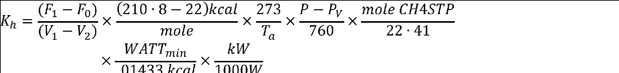
F0 = Flow of methane at baseline (1pm)
F1 = Higher preset flow of methane (1pm)
V0 = Thermopile voltage at baseline (mv)
V1 = Thermopile voltage at higher flow (mv)
Ta
= Ambient temperature (K)
P = Ambient pressure (mm Hg)
Pv = Water vapour pressure (mm Hg)
(2) Heat release rates may be calculated from the reading of the thermopile output voltage at any instant of time as:
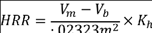
HRR = Heat Release Rate kW/m2
Vm = Measured thermopile voltage (mv)
Vb = Baseline voltage (mv)
Kh = Calibration Factor (kW/mv)
(3) The integral of the heat release rate is the total heat release as a function of time and is calculated by multiplying the rate by the data sampling frequency in minutes and summing the time from zero to two minutes.
(g) Criteria. The total positive heat release over the first two minutes of exposure for each of the three or more samples tested must be averaged, and the peak heat release rate for each of the samples must be averaged. The average total heat release must not exceed 65 kilowatt-minutes per square metre, and the average peak heat release rate must not exceed 65 kilowatts per square metre.
(h) Report. The test report must include the following for each specimen tested:
(1) Description of the specimen.
(2) Radiant heat flux to the specimen, expressed in Watts/cm2.
(3) Data giving release rates of heat (in kW/m2) as a function of time, either graphically or tabulated at intervals no greater than 10 seconds. The calibration factor (Kh) must be recorded.
(4) If melting, sagging, delaminating, or other behaviour that affects the exposed surface area or the mode of burning occurs, these behaviours must be reported, together with the time at which such behaviours were observed.
(5) The peak heat release and the 2 minute integrated heat release rate must be reported.
[Amdt 25/18]

FIGURE 1.
RELEASE RATE APPARATUS

(Unless denoted otherwise, all dimensions are in millimetres.)
FIGURE 2A.
“GLOBAR” RADIANT PANEL

(Unless denoted otherwise, all dimensions are in millimetres.)
FIGURE 2B.
“GLOBAR” RADIANT PANEL

(Unless denoted otherwise, all dimensions are in millimetres.)
FIGURE 3.

(Unless denoted otherwise, all dimensions are in millimetres.)
FIGURE 4.

FIGURE 5.
THERMOCOUPLE POSITION