CS ADR-DSN.U.930 Colours
for aeronautical ground lights
ED Decision 2017/021/R
(a) The chromaticity of aeronautical ground lights with filament-type light sources should be within the following boundaries:
CIE Equations (see Figure U-1A):
(1) Red
Purple boundary y = 0.980 – x
Yellow boundary y = 0.335
Note: see CS ADR-DSN.M.645(c)(2)(i)
(2) Yellow
Red boundary y = 0.382
White boundary y = 0.790 – 0.667x
Green boundary y = x – 0.120
(3) Green
Yellow boundary x = 0.360 – 0.080y
White boundary x = 0.650y
Blue boundary y = 0.390 – 0.171x
(4) Blue
Green boundary y = 0.805x + 0.065
White boundary y = 0.400 – x
Purple boundary x = 0.600y + 0.133
(5) White
Yellow boundary x = 0.500
Blue boundary x = 0.285
Green boundary y = 0.440 and y = 0.150 + 0.640x
Purple boundary y = 0.050 + 0.750x and y = 0.382
(6) Variable white
Yellow boundary x = 0.255 + 0.750y and y = 0.790 – 0.667x
Blue boundary x = 0.285
Green boundary y = 0.440 and y = 0.150 + 0.640x
Purple boundary y = 0.050 + 0.750x and y = 0.382
(b) Where increased certainty of recognition from white is more important than maximum visual range, green signals should be within the following boundaries:
(1) Yellow boundary y = 0.726 – 0.726x
(2) White boundary x = 0.625y – 0.041
(3) Blue boundary y = 0.390 – 0.171x
(c) Discrimination between lights having filament-type sources:
(1) If there is a requirement to discriminate yellow and white from each other, they should be displayed in close proximity of time or space as, for example, by being flashed successively from the same beacon.
(2) If there is a requirement to discriminate yellow from green and/or white, as for example on exit taxiway centre line lights, the y coordinates of the yellow light should not exceed a value of 0.40. The limits of white have been based on the assumption that they should be used in situations in which the characteristics (colour temperature) of the light source should be substantially constant.
(3) The colour variable white is intended to be used only for lights that are to be varied in intensity, e.g. to avoid dazzling. If this colour is to be discriminated from yellow, the lights should be so designed and operated that:
(i) the x coordinate of the yellow is at least 0.050 greater than the x coordinate of the white; and
(ii) the disposition of the lights should be such that the yellow lights are displayed simultaneously and in close proximity to the white lights.
(d) The chromaticity of aeronautical ground lights with solid state light sources, e.g. LEDs, should be within the following boundaries:
CIE Equations (see Figure U-1B):
(1) Red
Purple boundary y = 0.980 – x
Yellow boundary y = 0.335;
Yellow boundary y = 0.320.
Note: see CS ADR-DSN.M.645(c)(2)(i)
(2) Yellow
Red boundary y = 0.387
White boundary x = 0.980 – x
Green boundary y = 0.727x+0.054
(3) Green (refer also to GM1 ADR-DSN.U.930(d) and (e))
Yellow boundary x = 0.310
White boundary x = 0.625y – 0.041
Blue boundary y = 0.400
(4) Blue
Green boundary y = 1.141x – 0.037
White boundary x = 0.400 – y
Purple boundary x = 0.134 + 0.590y
(5) White
Yellow boundary x = 0.440
Blue boundary x = 0.320
Green boundary y = 0.150 + 0.643x
Purple boundary y = 0.050 + 0.757x
(6) Variable white
The boundaries of variable white for solid state light sources are those specified in CS ADR-DSN.U.930(d)(5) above.
(e) Colour measurement for filament-type and solid state light sources:
(1) The colour of aeronautical ground lights should be verified as being within the boundaries specified in Figure U-1A or U-1B, as appropriate, by measurement at five points within the area limited by the innermost isocandela curve in the isocandela diagrams in CS ADR DSN.U.940, with operation at rated current or voltage. In the case of elliptical or circular isocandela curves, the colour measurements should be taken at the centre and at the horizontal and vertical limits. In the case of rectangular isocandela curves, the colour measurements should be taken at the centre and the limits of the diagonals (corners). In addition, the colour of the light should be checked at the outermost isocandela curve to ensure that there is no colour shift that might cause signal confusion to the pilot.
(2) In the case of visual approach slope indicators and other light units having a colour transition sector, the colour should be measured at points in accordance with paragraph CS ADR-DSN.U.930(e)(1) above, except that the colour areas should be treated separately and no point should be within 0.5 degrees of the transition sector.
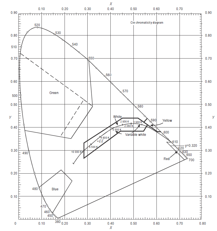
Figure U-1A.
Colours for aeronautical ground lights (filament-type lamps)
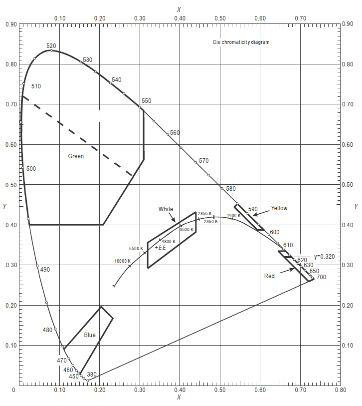
Figure U-1B.
Colours for aeronautical ground lights (solid state lighting)
[Issue: ADR-DSN/3]
[Issue: ADR-DSN/4]