ED Decision 2022/006/R
(a) Signs should be either fixed message signs or variable message signs.
(b) Applicability:
(1) Signs should be provided to convey a mandatory instruction, information on a specific location, or destination on a movement area or to provide other information necessary for the implementation of surface movement guidance and control system (SMGCS) at an aerodrome.
(2) A variable message sign should be provided where:
(i) the instruction or information displayed on the sign is relevant only during a certain period of time; and/or
(ii) there is a need for variable predetermined information to be displayed on the sign to meet the requirements of the implementation of surface movement guidance and control system (SMGCS) at an aerodrome.
(c) Characteristics:
(1) Signs should be frangible. Those located near a runway or taxiway should be sufficiently low to preserve clearance for propellers and the engine pods of jet aircraft. The installed height of the sign should not exceed the dimension shown in the appropriate column of Table N-1.
(2) Signs should be rectangular, as shown in Figures N-4 and N-6 with the longer side horizontal.
(3) The only signs on the movement area utilising red should be mandatory instruction signs.
(4) Signs should be illuminated when intended for use:
(i) in runway visual range conditions less than a value of 800 m; or
(ii) at night in association with instrument runways; or
(iii) at night in association with non-instrument runways where the code number is 3 or 4.
(5) Signs should be retroreflective and/or illuminated when intended for use at night in association with non-instrument runways where the code number is 1 or 2.
(6) Where variable pre-determined information is required, a variable sign should be provided.
(i) A variable message sign should show a blank face when not in use.
(ii) In case of failure, a variable message sign should not provide information that could lead to unsafe action from a pilot or a vehicle driver.
(iii) The time interval to change from one message to another on a variable message sign should be as short as practicable and should not exceed 5 seconds.
(7) The taxiing guidance signs should be in accordance with the specifications of paragraphs (c)(8) to (c)(22).
(8) The location distance for taxiing guidance signs including runway exit signs should conform to Table N-1.
|
Sign height (mm) |
Perpendicular distance from
defined taxiway pavement edge to near side of sign |
Perpendicular distance from
defined runway pavement edge to near side of sign |
|||
|
Runway code number |
Legend |
Face (min) |
Installed (max) |
||
|
1 or 2 |
200 |
400 |
700 |
5–11 m |
3–10 m |
|
1 or 2 |
300 |
600 |
900 |
5–11 m |
3–10 m |
|
3 or 4 |
300 |
600 |
900 |
11–21 m |
8–15 m |
|
3 or 4 |
400 |
800 |
1 100 |
11–21 m |
8–15 m |
Table N-1.
Location distances for taxiing guidance signs including runway exit signs
(9) Inscription heights should conform to the Table N-2.
|
Runway codenumber |
Minimum character height |
||
|
Mandatory instruction sign |
Information sign |
||
|
Runway exit and runway
vacated signs |
Other signs |
||
|
1 or 2 |
300 mm |
300 mm |
200 mm |
|
3 or 4 |
400 mm |
400 mm |
300 mm |
Table N-2.
Minimum character height
(10) Where a taxiway location sign is installed in conjunction with a runway designation sign (see CS ADR-DSN.N.785(b)(9)), the character size should be that specified for mandatory instruction signs.
(11) The dimensions should be as follows for:
(i) Arrow:
|
Legend height |
Stroke |
|
200 mm |
32 mm |
|
300 mm |
48 mm |
|
400 mm |
64 mm |
(ii) Stroke:
|
Legend height |
Stroke |
|
200 mm |
32 mm |
|
300 mm |
48 mm |
|
400 mm |
64 mm |
(12) Sign luminance should be as follows:
(i) Where operations are conducted in runway visual range conditions less than a value of 800 m, average sign luminance should be at least:
|
Red |
30 cd/m2 |
|
Yellow |
150 cd/m2 |
|
White |
300 cd/m2 |
(ii) Where operations are conducted in accordance with CS ADR-DSN.N.775(c)(4)(ii) and (c)(5), average sign luminance should be at least:
|
Red |
10 cd/m2 |
|
Yellow |
50 cd/m2 |
|
White |
100 cd/m2 |
Note: In runway visual range conditions less than a value of 400 m, there will be some degradation in the performance of signs.
(13) The luminance ratio between red and white elements of a mandatory instruction sign should be between 1:5 and 1:10.
(14) The average luminance of the sign is calculated by establishing grid points as shown in Figure N-1, and using the luminance values measured at all grid points located within the rectangle representing the sign.
(15) The average value is the arithmetic average of the luminance values measured at all considered grid points.
(16) The ratio between luminance values of adjacent grid points should not exceed 1.5:1. For areas on the sign face where the grid spacing is 7.5 cm, the ratio between luminance values of adjacent grid points should not exceed 1.25:1. The ratio between the maximum and minimum luminance value over the whole sign face should not exceed 5:1.
(17) The forms of characters, i.e. letters, numbers, arrows, and symbols should conform to those shown in Figures N-2A to N-2H. The width of characters and the space between individual characters should be determined as indicated in Table N-3.
(18) The face height of signs should be as follows:
|
Legend height |
Face height
(min) |
|
200 mm |
400 mm |
|
300 mm |
600 mm |
|
400 mm |
800 mm |
(19) The face width of signs should be determined using Figure N-3 except that, where a mandatory instruction sign is provided on one side of a taxiway only, the face width should not be less than:
(i) 1.94 m where the code number is 3 or 4; and
(ii) 1.46 m where the code number is 1 or 2.
(20) Borders:
(i) The black vertical delineator between adjacent direction signs should have a width of approximately 0.7 of the stroke width.
(ii) The yellow border on a stand-alone location sign should be approximately 0.5 stroke width.
(21) The colours of signs should be in accordance with the appropriate specifications in CHAPTER U — Colours for aeronautical ground lights, markings, signs and panels.
(22) If the runway threshold is displaced from the extremity of the runway, a sign showing the designation of the runway may be provided for aeroplanes taking off.
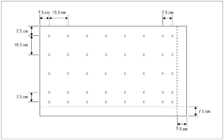
Note 1: The average luminance of a sign is
calculated by establishing grid points on a sign face showing typical
inscriptions and a background of the appropriate colour (red for mandatory
instruction signs and yellow for direction and destination signs) as follows:
(a) Starting
at the top left corner of the sign face, establish a reference grid point at
7.5 cm from the left edge and the top of the sign face.
(b) Create
a grid of 15 cm spacing horizontally and vertically from the reference
grid point. Grid points within 7.5 cm of the edge of the sign face should
be excluded.
(c) Where
the last point in a row/column of grid points is located between 22.5 cm
and 15 cm from the edge of the sign face (but not inclusive), an
additional point should be added 7.5 cm from this point.
(d) Where
a grid point falls on the boundary of a character and the background, the grid
point should be slightly shifted to be completely outside the character.
Note 2: Additional grid points may be required to
ensure that each character includes at least five evenly spaced grid points.
Note 3: Where one unit includes two types of signs,
a separate grid should be established for each type.
Figure N-1.
Grid points for calculating average luminance of a sign
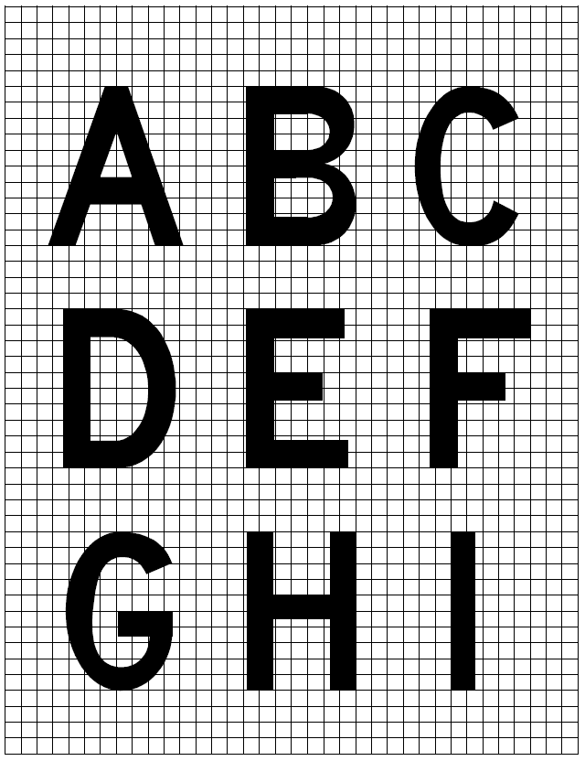
Figure N-2A.
Forms of characters for signs
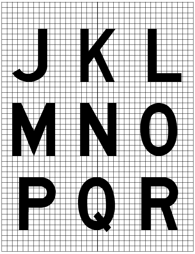
Figure N-2B.
Forms of characters for signs
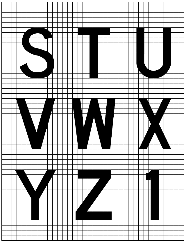
Figure N-2C.
Forms of characters for signs
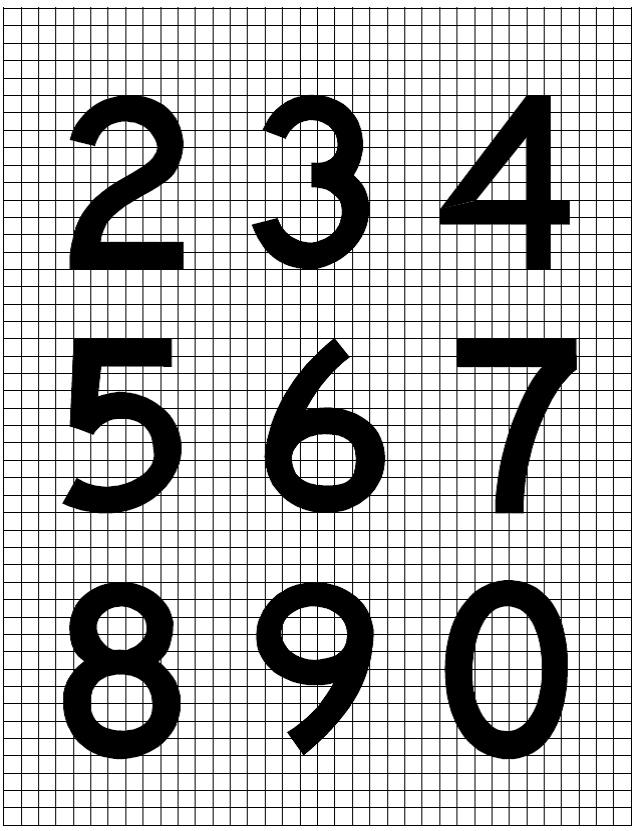
Figure N-2D.
Forms of characters for signs
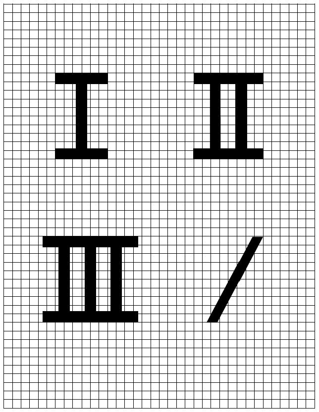
Figure N-2E.
Forms of characters for signs
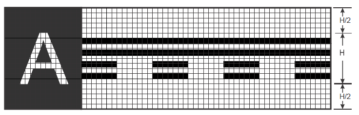
Figure N-2F.
Runway vacated signwith typical location sign
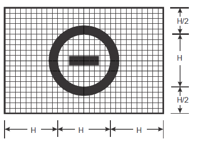
Figure N-2G.
No-entry sign
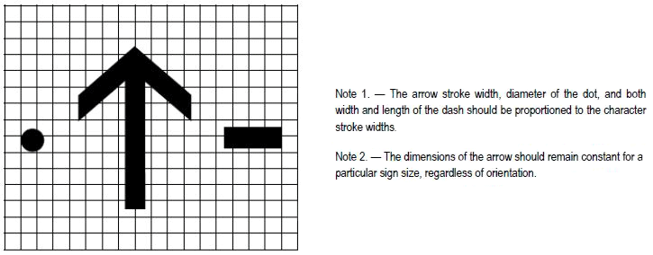
Figure N-2H.
Forms of characters for signs
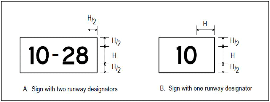
Figure N-3.
Sign dimensions
|
a)
Letter to letter code number |
|||
|
Preceding Letter |
Following
Letter |
||
|
B, D, E, F, H, I, K, L, M, N, P, R, U |
C, G, O, Q, S,
X, Z |
A, J, T, V, W,
Y |
|
|
Code number |
|||
|
A |
2 |
2 |
4 |
|
B |
1 |
2 |
2 |
|
C |
2 |
2 |
3 |
|
D |
1 |
2 |
2 |
|
E |
2 |
2 |
3 |
|
F |
2 |
2 |
3 |
|
G |
1 |
2 |
2 |
|
H |
1 |
1 |
2 |
|
I |
1 |
1 |
2 |
|
J |
1 |
1 |
2 |
|
K |
2 |
2 |
3 |
|
L |
2 |
2 |
4 |
|
M |
1 |
1 |
2 |
|
N |
1 |
1 |
2 |
|
O |
1 |
2 |
2 |
|
P |
1 |
2 |
2 |
|
Q |
1 |
2 |
2 |
|
R |
1 |
2 |
2 |
|
S |
1 |
2 |
2 |
|
T |
2 |
2 |
4 |
|
U |
1 |
1 |
2 |
|
V |
2 |
2 |
4 |
|
W |
2 |
2 |
4 |
|
X |
2 |
2 |
3 |
|
Y |
2 |
2 |
4 |
|
Z |
2 |
2 |
3 |
|
b)
Numeral to numeral code number |
|||
|
Preceding Numeral |
Following
number |
||
|
1, 5 |
2, 3, 6, 8, 9,
0 |
4, 7 |
|
|
Code number |
|||
|
1 |
1 |
1 |
2 |
|
2 |
1 |
2 |
2 |
|
3 |
1 |
2 |
2 |
|
4 |
2 |
2 |
4 |
|
5 |
1 |
2 |
2 |
|
6 |
1 |
2 |
2 |
|
7 |
2 |
2 |
4 |
|
8 |
1 |
2 |
2 |
|
9 |
1 |
2 |
2 |
|
0 |
1 |
2 |
2 |
|
c)
Space between characters |
|||
|
Code No. |
Character
height (mm) |
||
|
200 |
300 |
400 |
|
|
Space (mm) |
|||
|
1 |
48 |
71 |
96 |
|
2 |
38 |
57 |
76 |
|
3 |
25 |
38 |
50 |
|
4 |
13 |
19 |
26 |
|
d) Width of
letter |
|||
|
Letter |
Letter height
(mm) |
||
|
200 |
300 |
400 |
|
|
Width (mm) |
|||
|
A |
170 |
255 |
340 |
|
B |
137 |
205 |
274 |
|
C |
137 |
205 |
274 |
|
D |
137 |
205 |
274 |
|
E |
124 |
186 |
248 |
|
F |
124 |
186 |
248 |
|
G |
137 |
205 |
274 |
|
H |
137 |
205 |
274 |
|
I |
32 |
48 |
64 |
|
J |
127 |
190 |
254 |
|
K |
140 |
210 |
280 |
|
L |
124 |
186 |
248 |
|
M |
157 |
236 |
314 |
|
N |
137 |
205 |
274 |
|
O |
143 |
214 |
286 |
|
P |
137 |
205 |
274 |
|
Q |
143 |
214 |
286 |
|
R |
137 |
205 |
274 |
|
S |
137 |
205 |
274 |
|
T |
124 |
186 |
248 |
|
U |
137 |
205 |
274 |
|
V |
152 |
229 |
304 |
|
W |
178 |
267 |
356 |
|
X |
137 |
205 |
274 |
|
Y |
171 |
257 |
342 |
|
Z |
137 |
205 |
274 |
|
e) Width of numeral |
|||
|
Numeral |
Numeral height
(mm) |
||
|
200 |
300 |
400 |
|
|
Width (mm) |
|||
|
1 |
50 |
74 |
98 |
|
2 |
137 |
205 |
274 |
|
3 |
137 |
205 |
274 |
|
4 |
149 |
224 |
298 |
|
5 |
137 |
205 |
274 |
|
6 |
137 |
205 |
274 |
|
7 |
137 |
205 |
274 |
|
8 |
137 |
205 |
274 |
|
9 |
137 |
205 |
274 |
|
0 |
143 |
214 |
286 |
INSTRUCTIONS
1. To
determine the proper SPACE between letters or numerals, obtain the code number
from table a) or b) and enter table c) for that code number to the desired
letter or numeral height.
2. The
space between words or groups of characters forming an abbreviation or symbol
should be equal to 0.5 to 0.75 of the height of the characters used except
that where an arrow is located with a single character such as ‘A→‘, the space
may be reduced to not less than one quarter of the height of the character in
order to provide a good visual balance.
3. Where
the numeral follows a letter or vice versa, use Code 1.
4. Where
a hyphen, dot, or diagonal stroke follows a character or vice versa, use Code
1.
5. For the intersection take-off sign, the height of the lower case ‘m’ is 0.75 of the height of the preceding character. The spacing from the preceding character is at Code 1 for the character height in Table N-3(c).
Table N-3.
Letter and numeral width and space between letters or numerals
[Issue: ADR-DSN/3]
[Issue: ADR-DSN/4]
[Issue: ADR-DSN/6]