Appendix 2 to ETSO-C146e A1 – Addition to RTCA Document DO-229E, Section 1
ED Decision 2020/011/R
This Appendix describes the required modifications and additions to RTCA document DO-229E for compliance with this ETSO. This Appendix adds a new Section 1.8.3 on cybersecurity and GNSS spoofing mitigation and additional required leg types in Section 2.2.1.3 of RTCA document DO-229E.
The new Section, 1.8.3, contains no new requirements but provides information for cybersecurity and spoofing mitigation to make RTCA document DO-229E consistent with the new RTCA MOPS template and RTCA document DO-253D, Minimum Operational Performance Standards for GPS Local Area Augmentation System Airborne Equipment.
The new 2.2.1.3 leg type requirements are applicable to Class Gamma equipment only and are necessary to properly execute published instrument procedures designed to provide maximum efficiency, flexibility, and aircraft eligibility. These instrument procedure designs may include RNAV components and/or leg types associated with conventional procedures. The modifications and additions to Section 2.2.1.3 are necessary to ensure Class Gamma equipment can properly execute current and future instrument procedure designs.
1.8.3 Cybersecurity and GNSS Spoofing Mitigation
This section contains information to address intentional interference with the GNSS. Spoofing is caused by RF waveforms that mimic true signals in some ways, but deny, degrade, disrupt, or deceive a receiver’s operation when they are processed. Spoofing may be unintentional, such as effects from the signals of a GNSS repeater, or may be intentional and even malicious. There are two classes of spoofing. Measurement spoofing introduces RF waveforms that cause the target receiver to produce incorrect measurements of time of arrival or frequency of arrival or their rates of change. Data spoofing introduces incorrect digital data to the target receiver for its use in processing of signals and the calculation of PNT. Either class of spoofing can cause a range of effects, from incorrect outputs of PNT to receiver malfunction. The onset of effects can be instantaneous or delayed, and the effects can continue even after the spoofing has ended. Improperly used or installed GNSS re-radiators act like spoofers. Re-radiators, replay and GNSS emulator devices can present misleading information to GNSS equipment and/or could cause lasting effects.
Equipment manufacturers should implement measures to mitigate processing of erroneous data. Cross-checks of GNSS sensor data against independent position sources and/or other detection monitors using GNSS signal metrics or data checks can be implemented in the antenna, receiver, and/or through integration with other systems at the aircraft level. Data validity checks to recognize and reject measurement and data spoofing should be implemented in the receiver. Additional guidance and best practices related to GNSS equipment can be found in the U.S. Department of Homeland Security document ‘Improving the Operation and Development of Global Positioning System (GPS) Equipment Used by Critical Infrastructure’[13] and GLOBAL POSITIONING SYSTEMS DIRECTORATE SYSTEMS ENGINEERING & INTEGRATION: INTERFACE SPECIFICATION, IS-GPS-200, Navstar GPS Space Segment/Navigation User Interfaces, Revision H, IRN-IS-200H-003 28 July 2016.
Aircraft equipment information vulnerabilities (such as cybersecurity risks) have been present for digital systems since the development of the personal computer (PC) in the late 1970s and even longer for RF systems, and the advent of internet connectivity has substantially increased those risks. Typically, access to navigation receivers has been controlled such that they are considered to be vulnerable only through RF signals and OEM and/or aircraft operator controlled processes for maintenance and updates. In some cases, aircraft GNSS receivers may be field loadable by approved personnel, requiring physical access and physical interface to the ground receivers. However, it is expected that not all aircraft in the future will rely on such physical isolation for the security of avionics. Internet and Wi-Fi connectivity have become popular as a means for aircraft or equipment manufacturers to update installed avionics software, to update databases, or provide an alternate means of communicating with the flight crew or cabin (e.g. in-flight entertainment, weather, etc.).
In most countries, the State provides oversight of safety-of-flight systems (sometimes referred to as ‘authorised services’) which provide information to aircraft, such as ILS, VOR, GNSS, and DME, to name a few. However, the State typically does not provide oversight on ‘non-trusted’ connectivity such as the internet, Wi-Fi, or manufacturer-supplied equipment interfaces which permit the input of externally supplied data into aircraft systems. A manufacturer may expose aircraft information vulnerabilities through the design of the equipment, or the equipment may become vulnerable as a result of being connected to a common interface. Therefore, it is important for manufacturers to consider aircraft information security risk mitigation strategies in their equipment design, particularly when the equipment is responsible for an interface between the aircraft and aircraft-external systems.
Apart from any specific aircraft-information-security-related performance requirements that are contained in the MOPS, it is recommended that manufacturers consider a layered approach to aircraft information security risk mitigation that includes both technical (e.g., software, signal filtering) and physical strategies. From a technical perspective, for example, this could include signal spoofing detection capabilities or more stringent, multi-factored authentication techniques such as passwords, PINs, and digital certificates. From a physical perspective, a manufacturer could consider connectors that require special tools to remove them to prevent passenger tampering — although navigation avionics are typically located in an avionics bay inaccessible to passengers. And finally, but just as important, manufacturers should consider supply chain risk management; for example, if a manufacturer outsources the development of software code, is the contractor and its staff properly vetted?
Civil aviation authorities (CAAs) have a regulatory interest when an applicant’s design makes use of a non‑trusted connection through which the installation can potentially introduce aircraft information security vulnerability. This requires the applicant to address not only the information security vulnerabilities and mitigation techniques for the new installation, but to also consider how vulnerabilities could propagate to existing downstream systems. Therefore, it is recommended that manufacturers reference their equipment aircraft information security review and mitigation strategies in the installation manual of the equipment so that the applicant can consider them in meeting the regulatory requirements of the installation.
2.2.1.3 Path Definition
Replace the list of required leg types in the first paragraph after the last sentence as shown:
The desired path shall be defined according to the following leg types:
Leg Type |
Description |
IF |
Initial Fix |
CF |
Course to Fix leg |
DF |
Direct to Fix leg |
TF |
Track to Fix leg |
FA |
Fix to Altitude leg |
FM |
Fix to Manual Termination |
VA |
Heading to Altitude leg |
VI |
Heading to Intercept |
VM |
Heading to Manual Termination |
CA |
Course to Altitude Leg |
Holding legs
Leg Type |
Description |
HA |
Terminates at an altitude |
HF |
Terminates at a fix after one orbit |
HM |
Manual termination |
Note 1: There is no intent to require a heading or altitude source connected to the equipment to automatically execute leg types with heading or altitude components. Manual equipment inputs for heading/altitude with manual aircraft control methods are acceptable for these leg types.
Note 2: Cross-track deviation requirements are not applicable for VA, VI, and VM heading leg types.
Replace Section 2.2.1.3.6 as shown and add the following leg type descriptions. Renumber existing paragraphs (starting with 2.2.1.3.7) to account for the newly added sections:
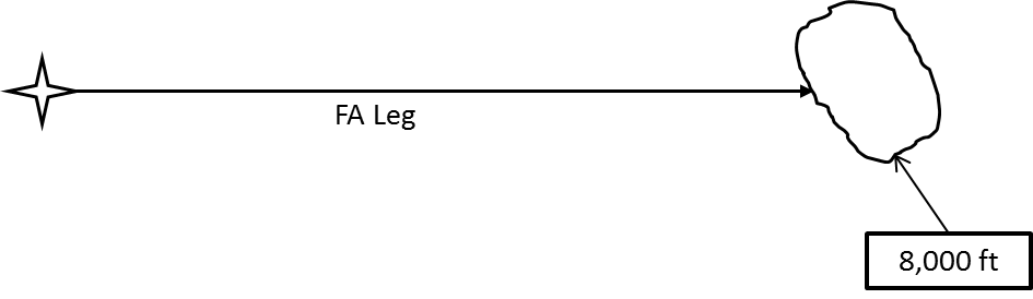
2.2.1.3.6 Fix to Altitude (FA)
An FA leg shall be defined as a specified track over the ground from a database waypoint to a specified altitude at an unspecified position.
2.2.1.3.7 Fix to Manual Termination (FM)
An FM leg shall be defined as a specified track over the ground from a database fix until a manual termination of the leg.

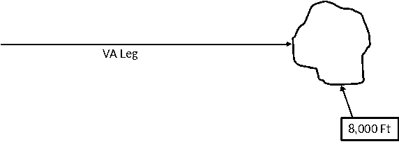
2.2.1.3.8 Heading to Altitude (VA)
A VA leg shall be defined as a specified heading to a specific altitude termination at an unspecified position. No correction is made for wind.
2.2.1.3.9 Heading to Intercept (VI)
A VI leg shall be defined as a specified heading to intercept a subsequent leg at an unspecified position. No correction is made for wind.

2.2.1.3.10 Heading to Manual Termination (VM)
A VM leg shall be defined as a specified heading until a manual termination of the leg. No correction is made for wind.

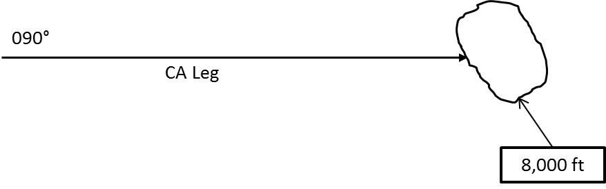
2.2.1.3.12 Course to Altitude (CA)
A CA leg shall be defined as a specified course to a specific altitude at an unspecified position. The course is flown making adjustment for wind.
2.2.1.3.13 Hold to Altitude (HA)
An HA leg is a holding pattern which terminates at the next crossing of the hold fix when the aircraft altitude is at or above the specified altitude. The altitude is provided by the navigation database. The source of the magnetic variation needed to convert magnetic courses to true courses is detailed in Section 2.2.1.3.12.
2.2.1.3.14 Hold to Fix (HF)
An HF leg is a holding pattern which terminates at the first crossing of the hold fix after becoming established on the inbound course. This is typically after the entry procedure is performed. The source of the magnetic variation needed to convert magnetic courses to true courses is detailed in Section 2.2.1.3.12.
2.2.1.3.14 Hold for Clearance (manual termination) (HM)
An HM leg is a holding pattern which terminates only after flight crew action. The source of the magnetic variation needed to convert magnetic courses to true courses is detailed in Section 2.2.1.3.12.
Table 2-14 to Table 2-20
The tables incorrectly reference and label EUROCAE ED-14/RTCA document DO-160 Sections 16.5.1.2 and 16.6.1.2 regarding ‘2.1.1.7 Acquisition Time’ and ‘2.1.1.9 Reacquisition Time’. Change the table references as follows:
The MOPS Initial Acquisition Time requirement (2.1.1.7) applies to both AC and DC equipment under abnormal operating conditions (EUROCAE ED-14/RTCA document DO-160 Sections 16.5.2 and 16.6.2) and the satellite reacquisition time requirement (2.1.1.9) applies to both AC and DC equipment under normal operating conditions (EUROCAE ED-14/RTCA document DO-160 Sections 16.5.1 and 16.6.1).
[Amdt ETSO/13]
[Amdt ETSO/16]