Appendix 1 to ETSO-C117b – EASA Performance Standard for Airborne Wind Shear Warning and Escape Guidance Systems for Transport Aeroplanes
ED Decision 2020/011/R
1. PURPOSE
This Appendix establishes the minimum performance standard (MPS) for airborne wind shear warning and escape guidance systems for transport category aeroplanes.
2. SCOPE
The scope of this Appendix is to provide MPS for airborne wind shear warning and escape guidance systems for transport category aeroplanes. All the paragraph references cited herein are in reference to this Appendix only.
This performance standard applies only to wind shear warning systems which identify wind shear phenomena by sensing an encounter with conditions that exceed the threshold values contained in this performance standard. In addition to wind shear warning criteria, this performance standard provides criteria that are applicable to systems that provide optional wind shear caution alert capabilities. Wind shear escape guidance is provided to assist the pilot in obtaining the desired flight path during such an encounter.
3. DEFINITION OF TERMS
a. Airborne wind shear warning system
A device or system which uses various sensor inputs to identify the presence of wind shear once the phenomenon is encountered, and provides the pilot with a timely warning. The system may include both wind shear warning and wind shear caution alerts. A warning device of this type does not provide escape guidance information to the pilot to satisfy the criteria for warning and flight guidance systems.
b. Airborne wind shear warning and escape guidance system
A device or system which uses various sensor inputs to identify the presence of wind shear once the phenomenon is encountered, and provides the pilot with a timely warning and adequate flight guidance to improve the probability of recovery from the wind shear encounter. This system may include both wind shear warning and wind shear caution alerts.
c. Airborne wind shear auto recovery system
A device or system which integrates or couples autopilot and/or autothrottle systems of the aeroplanes with an airborne wind shear flight guidance system.
d. Airborne wind shear escape guidance system
A system which provides the crew with flight guidance information to improve the probability of recovery once a wind shear phenomenon is encountered.
e. Failure
The inability of a system, subsystem, unit, or part to perform within the previously specified limits.
f. False warning or caution
A warning or caution which occurs when the wind shear warning or caution threshold of the system is not exceeded.
g. Nuisance warning or caution
A warning or caution which occurs when a phenomenon is encountered, such as turbulence, which does not, in fact, endanger the aeroplane because of the duration of the subsequent change in the magnitude of the wind shear.
h. Recovery procedure
A vertical flight path control technique that is used to maximise the potential for a recovery from an inadvertent encounter with wind shear.
i. Severe wind shear
A wind shear of sufficient intensity and duration that it exceeds the performance capability of a particular aeroplane type. This would be likely to cause an inadvertent loss of control or ground contact if the pilot did not have information available from an airborne wind shear warning and escape guidance system which meets the criteria of this ETSO.
j. Wind shear caution alert
An alert that is triggered by increasing performance conditions, which is set at a wind shear level that requires immediate crew awareness and probably subsequent corrective action by the pilot.
k. Wind shear warning alert
An alert that is triggered by decreasing performance conditions, which is set at a wind shear level that requires immediate corrective action by the pilot.
4. GENERAL REQUIREMENTS
In addition to the performance requirements provided in the main text of this Performance Standard and in the Appendices to ETSO-C117b, the following general requirements and equipment characteristics are defined below:
a. General standards
The following general requirements shall be met by all wind shear warning and escape guidance systems:
(1) Airworthiness
The design and manufacture of the airborne equipment shall provide for installation so as not to impair the airworthiness of the aeroplane The material shall be of a quality which experience and/or tests have demonstrated to be suitable and dependable for use in aeroplane systems. The workmanship shall be consistent with high-quality aeroplane electromechanical and electronic component manufacturing practices.
(2) General performance
The equipment shall perform its intended function, as defined by the manufacturer.
(3) Fire resistance
Except for small parts (such as knobs, fasteners, seals, grommets and small electrical parts) that would not significantly contribute to the propagation of fire, all the materials that are used shall be self-extinguishing. One means to show compliance with this requirement is contained in Part 25, Appendix F.
(4) Operation of controls
Controls that are intended for use during flight shall be designed to minimise errors, and when operated in any possible combinations and sequences, shall not result in a condition whose presence or continuation would be detrimental to the continued performance of the equipment.
(5) Accessibility of controls
Controls that are not normally adjusted in flight shall not be readily accessible to the operator.
(6) Interfaces
The interfaces with other aeroplane equipment shall be designed such that the normal or abnormal operation of the wind shear warning and escape guidance equipment does not adversely affect the operation of other equipment.
(7) Compatibility of components
If a system component is individually acceptable but requires calibration adjustments or matching to other components in the aeroplane for its proper operation, it shall be identified in a manner that will ensure its performance to the requirements specified in this ETSO.
(8) Interchangeability
System components which are identified with the same manufactured part number shall be completely interchangeable.
(9) Control/display capability
A suitable interface shall be provided to allow data input, data output, and control of the operation of the equipment. The control/display shall be operable by one person with the use of only one hand.
(10) Control/display readability
The equipment shall be designed so that all the displays and controls are readable under all cockpit ambient light conditions, ranging from total darkness to reflected sunlight, and are arranged to facilitate the use of the equipment. If limitations are necessary on equipment installations to ensure that the displays are readable, they shall be included in the installation instructions.
(11) Effects of test procedures
The design of the equipment shall be such that the application of the specified test procedures does not produce a condition that is detrimental to the performance of the equipment, except as specifically allowed.
(12) Equipment computational response time
The equipment shall employ suitable update rates for the computation and display of detection and guidance information.
(13) Supplemental heating or cooling
If supplemental heating or cooling is required by system components to ensure that the requirements of this ETSO are met, they shall be specified by the equipment manufacturer in the installation instructions.
(14) Self-test capability
The equipment shall employ a self-test capability to verify the proper operation of the system.
(i) Any manually initiated self-test mode of operation shall automatically return the system to the normal operating mode upon completion of a successful test.
(ii) Any automatically activated self-test feature shall annunciate this mode of operation to the pilot if this feature activates annunciation lights, aural messages, or displaces the guidance commands in any way.
(iii) Use of the system self-test feature shall not adversely affect the performance of operation of other aeroplane systems.
(iv) A failure of the system to successfully pass the self-test shall be annunciated.
(15) Independence of warning and escape guidance functions
Irrespective of whether the warning and escape guidance functions are in a combined system or are separate systems, they should be sufficiently independent such that a failure of either system does not necessarily preclude or inhibit the presentation of information from the other. A warning system failure shall not result in any ambiguous or erroneous guidance system mode annunciations.
(16) System reliability
(i) The probability of a false warning being generated within the wind shear warning system or the wind shear warning and escape guidance system shall be 1E-4 or less per flight hour.
(ii) The probability of an unannunciated failure of the wind shear warning system or the wind shear warning and escape guidance system shall be 1E 5 or less per flight hour (reserved).
b. Equipment functional requirements — standard conditions
The equipment shall meet the following functional requirements:
(1) Mode annunciation
The mode of operation of the wind shear escape guidance display shall be annunciated to the pilot upon activation of the escape guidance during a wind shear encounter, and upon reversion to a different flight guidance mode.
(2) Malfunction/failure indications
The equipment shall indicate:
(i) any inadequacy or absence of primary power;
(ii) equipment failures;
(iii) inadequate or invalid warning or guidance displays or output signals; and
(iv) inadequate or invalid sensor signals or sources.
These malfunction/failure indications shall occur independently of any operator actions. The lack of adequate warning displays, escape guidance information, or sensor signals or sources shall be annunciated when compliance with the requirements of this ETSO cannot be assured.
(3) Wind shear caution alert
If the equipment includes a wind shear caution:
(i) it shall provide an annunciation of increasing performance shear (updraft, increasing headwind, or decreasing tailwind) in accordance with the shear intensity curve shown in Figure 1;
(ii) this caution alert shall display or provide an appropriate output for display of an amber caution annunciation dedicated for this purpose. An aural alert may be provided as an option. The caution display (or output) should remain until the threshold wind shear condition no longer exists (not less than 3 seconds) or a wind shear warning alert occurs; and
(iii) gust conditions shall not cause a nuisance caution alert. Turbulence shall not cause more than one nuisance caution alert per 250 hours (or 3 000 flight cycles based on 1 hour/flight cycle) of system operation.
(4) Wind shear warning alert
(i) A wind shear warning alert shall provide an annunciation of decreasing performance shear (downdraft, decreasing headwind, or increasing tailwind) with a magnitude that is greater than or equal to that shown in the shear intensity curve shown in Figure 1.
(ii) This warning alert shall display or provide an appropriate output for display of a red warning annunciation labelled ‘wind shear’ dedicated for this purpose. The visual alert should remain at least until the threshold wind shear condition no longer exists, or for a minimum of 3 seconds, whichever is greater. An aural alert shall be provided that annunciates ‘wind shear’ for 3 aural cycles. The aural alert need not be repeated for subsequent wind shear warning alerts within the same mode of operation.
(iii) Gust conditions shall not cause a nuisance warning alert. Turbulence shall not cause more than 1 nuisance warning alert per 250 hours (or 3 000 flight cycles based on 1 hour/flight) of system operation.
(5) Wind shear alert with increased approach sensitivity and reduced take-off sensitivity modes
(i) Increased approach sensitivity mode. If the system separates the approach and take-off scenarios, the crew may reduce the shear intensity level in the approach mode to increase the probability of providing timely wind shear alerts. They may lower the floor of the shear intensity curve ‘must alert’ curve in Figure 1 from 0.105 to 0.090. If they lower the floor, they may also modify the turbulence rejection tests in paragraph 4(d)(7)(ii) such that an alert in this region is not a failure of the turbulence rejection test.
(ii) Reduced take-off sensitivity mode. If the system separates the approach and take-off scenarios, the crew may desensitise the take-off mode to reduce the probability of unwanted alerts. They may raise the floor of the shear intensity ‘must alert’ curve in Figure 1 from 0.105 to 0.120.
(iii) Additional reduced take-off sensitivity mode. Some high performance jet aeroplanes receive unwanted wind shear alerts after take-off when climbing at high rates through atmospheric wind gradients. If these unwanted alerts risk desensitising pilots to wind shear alerting, the crew may tailor the floor of the shear intensity ‘must alert’ curve in Figure 1 to reduce these unwanted alerts under the following conditions:
(a) The airborne wind shear warning and escape guidance system can determine that the aeroplane is in the take-off versus approach phase.
(b) The aeroplane is climbing at a high rate of climb, the aeroplane continues to climb at a high rate, and the rate of climb is known to create unwanted wind shear alerts.
(c) The aeroplane power setting is at or near a level that is representative of the maximum for the segment of the take-off; for example, maximum take-off thrust.
(d) The Figure 1 shear intensity ‘must alert’ curve shall be complied with after take-off.
(6) Alerting prioritisation
If alerting is prioritised in the presentation for a wind shear warning and escape guidance system (reactive wind shear), forward-looking wind shear system, terrain awareness and warning system, ground proximity warning system, traffic collision avoidance system, or when a simultaneous aural annunciation could occur, sequencing shall be implemented that ensures that reactive wind shear warning alerts are presented or annunciated first. Reactive wind shear alerts that are cautions have a lower priority than all terrain awareness and warning or ground proximity warning system alerts.
(7) The reactive wind shear systems caution alert should be disabled if a forward looking wind shear system is in operation. It is acceptable to issue reactive wind shear caution alerts if the forward-looking wind shear system is inoperative.
(8) Operating altitude range
The system shall be designed to function from at least 50 feet above ground level (AGL) to at least 1 000 feet AGL.
(9) Wind shear escape guidance
Flight guidance algorithms shall incorporate the following design considerations:
(i) At the point of the system warning threshold, the available energy of the aeroplane shall be properly managed through a representative number of wind field conditions. These conditions shall take into account significant shear components in both the horizontal and vertical axes, individually and in combination.
(ii) The flight path guidance commands shall be suitable for the dynamic response of aeroplane of the type on which the system is intended for installation. The applicant shall demonstrate that the flight guidance commands during a dynamic wind shear encounter can be followed without resulting in pilot induced oscillations.
(iii) If the magnitude of the shear components is such as to overcome the performance capability of the aeroplane, guidance commands shall be such that a ground impact will occur in the absence of the ability to produce additional lift, an absence of excessive kinetic energy, and without putting the aeroplane into a stalled condition.
(iv) Flight guidance command information shall be provided for presentation on the primary flight display/attitude direction indicator (PFD/ADI) and any available head-up display (HUD).
(v) Flight guidance displays which command the flight path and pitch attitude should be limited to an angle of attack that is equivalent to the onset of a stall warning or a maximum pitch command of 27°, whichever is less.
(vi) Flight guidance commands and any auto recovery mode (if included) may be automatically activated concurrently with or after the wind shear warning alert occurs, or may be manually selected. If manual selection is utilised, it shall only be via the take-off/go-around (TOGA) switch or equivalent means (i.e. a function of the throttle position, other engine parameters, etc.).
(vii) Manual deselection of wind shear flight guidance and any auto recovery mode (if included) shall be possible by means other than the TOGA switches.
(viii) Systems that incorporate the automatic reversion of flight guidance commands from wind shear escape guidance to another flight guidance mode should provide a smooth transition between the modes. Flight guidance commands shall not be removed from the flight guidance display until either they are manually deselected or until the aeroplane, following the end of the warning conditions, has maintained a positive rate of climb and speed above 1.3 Vs1 for at least 30 seconds.
FIGURE 1 — SHEAR INTENSITY CURVE
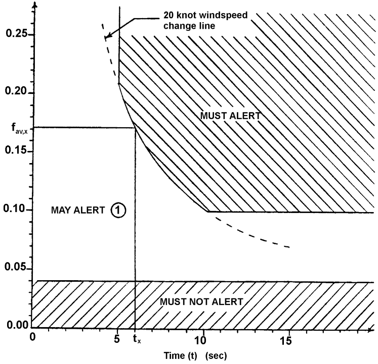
fav,x = average shear intensity to cause a warning at time tx (resulting in a 20-knot wind speed change, bounded as shown; applies to horizontal, vertical, and combination shear intensities),
= ,
whereby f(t) = instantaneous shear intensity at time t.

c. Equipment performance — environmental conditions
(1) The environmental tests and performance requirements described in this subsection are intended to provide a laboratory means to determine the overall performance characteristics of the equipment under conditions that are representative of those that may be encountered in actual operations. Table 1 defines the environmental tests that are required for the equipment. It shows the section numbers in ED-14G that describe the individual environmental tests. Some of the environmental tests contained in this subsection do not need to be performed unless the manufacturer wishes to qualify the equipment for that particular environmental condition. These tests are identified by the phrase ‘When required’ in Table 1. If the manufacturer wishes to qualify the equipment to these additional environmental conditions, then these ‘When required’ tests shall be performed.
(2) Environmental requirements. The following subset of performance requirements shall be met under the environmental conditions required by paragraph 3.1.2 of this ETSO. Additionally, all the system controls, displays, inputs and outputs shall perform their intended functions when subjected to the ED-14G environmental conditions.
(i) Section 4.b(1) — Mode Annunciation
(ii) Section 4.b(2) — Malfunction/Failure Indications
(iii) Section 4.b(3) — Wind Shear Caution Alert, except paragraph 4.b(3)(iii)
(iv) Section 4.b(4) — Wind Shear Warning Alert, except paragraph 4.b(4)(iii)
(v) Section 4.b(5) — Wind Shear Alert with Increased Approach Sensitivity and Reduced Take-off Sensitivity Modes
(vi) Section 4.b(9) — Wind Shear Escape Guidance
(3) The applicant shall conduct environmental qualification tests for the following shear intensity (fav,x) and exposure time (s) in Figure 1: 0.1050, 10; 0.1748, 6; and 0.2100, 5; and ensure that the system generates and displays alerts when required. A single representative wind shear waveform may be used for all the environmental tests if the system design is such that different waveforms will not affect the performance under environmental conditions. Gust and turbulence rejection tests are not required under environmental conditions.
Table 1 — Required EUROCAE ED-14G Testing by Category
Environmental Test |
ED-14G Section |
Required Test |
Temperature and Altitude |
4 |
|
Ground Survival Low Temperature and Short-Time Operating Low Temperature |
|
√ |
Low Operating Temperature |
|
√ |
Ground Survival High Temperature and Short-Time Operating High Temperature |
|
√ |
High Operating Temperature |
|
√ |
In-Flight Loss of Cooling |
|
When required |
Altitude |
|
√ |
Decompression |
|
When required |
Overpressure |
|
When required |
Temperature Variation |
5 |
√ |
Humidity |
6 |
√ |
Operational Shocks and Crash Safety |
7 |
|
Operational Shocks |
|
√ |
Crash Safety |
|
√ |
Vibration |
8 |
√ |
Explosion Proofness |
9 |
When required |
Waterproofness |
10 |
|
Condensing Water Proof |
|
When required |
Drip Proof |
|
When required |
Spray Proof |
|
When required |
Continuous Stream Proof |
|
When required |
Fluids Susceptibility |
11 |
|
Spray |
|
When required |
Immersion |
|
When required |
Sand and Dust |
12 |
When required |
Fungus Resistance |
13 |
When required |
Salt Spray |
14 |
When required |
Magnetic Effect |
15 |
√ |
Power Input |
16 |
|
Normal Operating Conditions (AC/DC) |
|
√ |
Abnormal Operating Conditions (AC/DC) |
|
√ |
Load Equipment Influence on Aeroplane Electrical Power System (AC/DC) |
|
When required |
Voltage spike |
17 |
|
Category A Requirements (If applicable) |
|
√ |
Category B Requirements (If applicable) |
|
√ |
Audio frequency conducted susceptibility |
18 |
√ |
Induced Signal Susceptibility |
19 |
√ |
RF Susceptibility |
20 |
√ |
Emission of RF Energy |
21 |
√ |
Lightning-induced Transient Susceptibility |
22 |
√ |
Lightning Direct Effects |
23 |
When required |
Icing |
24 |
When required |
Electrostatic Discharge |
25 |
When required |
Fire, Flammability |
26 |
√ |
d. Equipment test procedures
(1) Definitions of terms and conditions of tests. The following definitions of terms and conditions of tests are applicable to the equipment tests specified herein:
(i) Power input voltage. Unless otherwise specified, all the tests shall be conducted with the power input voltage adjusted to the design voltage ± 2 per cent. The input voltage shall be measured at the input terminals of the equipment under test.
(ii) Power input frequency
(a) In the case of equipment that is designed for operation from an AC power source of essentially constant frequency (e.g. 400 Hz), the input frequency shall be adjusted to the design frequency ± 2 per cent.
(b) In the case of equipment designed for operation from an AC power source of variable frequency (e.g. 300 to 1 000 Hz), unless otherwise specified, the test shall be conducted with the input frequency adjusted to within 5 % of a selected frequency and within the range for which the equipment is designed.
(iii) Wind field models. Unless otherwise specified, the wind field models used for the tests shall be those specified in Appendix 2 to ETSO-C117b.
(iv) Adjustment of equipment. The circuits of the equipment under test shall be aligned and adjusted in accordance with the manufacturer’s recommended practices prior to the application of the specified tests.
(v) Test instrument precautions. Due precautions shall be taken during the execution of the tests to prevent the introduction of errors that result from the connection of voltmeters, oscilloscopes, and other test instruments across the input and output impedances of the equipment under test.
(vi) Ambient conditions. Unless otherwise specified, all the tests shall be made within the following ambient conditions:
— Temperature: + 15 to + 35 °C (+ 59 to + 95 °F)
— Relative humidity: Not greater than 85 %
— Ambient pressure: 84–107 kPa (equivalent to + 5 000 to – 1 500 ft) (+ 1 525 to – 460 m)
(vii) Warm-up period. Unless otherwise specified, all the tests shall be conducted after the manufacturer’s specified warm-up period.
(viii) Connected loads. Unless otherwise specified, all the tests shall be performed with the equipment connected to loads which have the impedance values for which it is designed.
(2) Test procedures. The equipment shall be tested in all the modes of operation that allow different combinations of sensor inputs to show that it meets both the functional and accuracy criteria.
Dynamic testing provides quantitative data regarding the performance of wind shear warning and escape guidance equipment using a simplified simulation of flight conditions. This testing, when properly performed and documented, may serve to minimise the flight test requirements.
It shall be the responsibility of the equipment manufacturer to determine that the sensor inputs, when presented to the wind shear warning and escape guidance equipment, will produce performance that is commensurate with the requirements of this standard. Additional sensor inputs may be optionally provided to enhance the capability and/or performance of the equipment.
The equipment required to perform these tests shall be defined by the equipment manufacturer as a function of the specific sensor configuration of the equipment. Since these tests may be accomplished in more than one way, alternative test equipment set ups may be used where equivalent test functions can be accomplished. Combinations of tests may be used wherever appropriate.
The signal sources of the test equipment shall provide the appropriate signal formats for input to the specific system under test without contributing to the error values that are being measured. Tests need only be performed once, unless it is otherwise indicated.
The scenarios that are established for testing wind shear warning and escape guidance systems represent realistic operating environments to properly evaluate such systems. The wind field models contained in Appendix 2 to ETSO C117b should be used to evaluate the performance of the wind shear warning and escape guidance systems. The manufacturer may propose different wind field models provided that it is shown that they represent conditions that are at least as severe as those contained in this ETSO.
Note: The test waveform parameters provided in this ETSO are sufficiently broad to cover the wind field parameters that were observed in the known accident cases. However, the manufacturer is encouraged to verify that the detection systems will actually detect these wind shears by subjecting them to the wind field conditions specified for use in evaluating guidance commands.
(3) Test set-up. Simulator tests shall be used to demonstrate the performance capability of the wind shear warning and escape guidance equipment. A suitable equipment interface shall be provided for recording the relevant parameters that are necessary to evaluate the particular system under test. The aeroplane simulator shall be capable of appropriate dynamic modelling of a representative aeroplane and of the wind field and turbulence conditions contained in Appendices 2 and 3 to this ETSO, or other wind field/turbulence models that are found to be acceptable by the administrator.
Note: This section requires testing in a single representative aeroplane simulator. Approval of the installation will require system testing in an aeroplane simulator that is representative of the aeroplane. Thus, we recommend you to accomplish the paragraph 4(d)(3) simulator testing in as many representative simulators as are necessary to cover all the intended installations.
(4) Functional performance (paragraphs 4(b)(1) through 4(b)(5), 4(b)(8) and 4(b)(9)). Each of the functional capabilities identified in paragraphs 4(b)(1) through 4(b)(5), 4(b)(7) and 4(b)(8) shall be demonstrated with the wind shear warning and escape guidance equipment powered. These capabilities shall be evaluated either by inspection or in conjunction with the tests described in paragraphs 4(d)(5) through 4(d)(10).
(5) Mode annunciation (paragraph 4(b)(1)). With the equipment operating, verify that the wind shear escape guidance display mode of operation is annunciated to the pilot upon activation of the escape guidance and upon reversion to a different flight guidance mode.
(6) Malfunction/failure indications (paragraph 4(b)(2)). Configure the equipment for simulation tests as defined in paragraph 4(d)(3).
(i) With the system active (within the operating altitude range) and inactive (outside the operating altitude range), remove one at a time each required electrical power input to the equipment. There shall be a failure indication by the equipment of each simulated failure condition.
(ii) With the system active (within the operating altitude range) and inactive (outside the operating altitude range), cause each sensor or other signal input to become inadequate or invalid. There shall be a failure indication by the equipment of each simulated failure condition.
(7) Wind shear caution alert (paragraphs 4(b)(3) and 4(b)(5)(i)). For equipment that incorporates a wind shear caution alert function, accomplish the following tests:
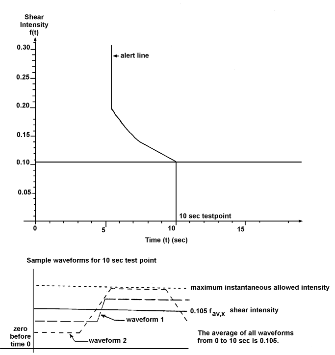
(i) Configure the equipment for a simulation test as defined in paragraph 4(d)(3). Subject the equipment to acceleration waveform values that meet the following conditions (reference Figure 2). The system shall generate an appropriate caution alert (or no alert) within the time intervals specified when subjected to the following average shear intensity (fav,x) values:
fav,x (1) |
Time of Exposure (t) (s) |
Alert within (s) (3) |
0.0200 |
20 |
no alert |
0.0400 |
20 |
no alert |
0.1050 |
10 |
10 |
0.1166 |
9 |
9 |
0.1311 |
8 |
8 |
0.1499 |
7 |
7 |
0.1748 |
6 |
6.2 |
0.2100 |
5 |
5.7 |
0.2700 (2) |
5 |
5 |
Notes:
(1) The average shear intensity which shall result in a caution alert after a time tx or less meets the definition of fav,x in Figure 1. The maximum instantaneous shear intensity of the test waveform is restricted to 0.075 or 100 % of fav,x above the average shear value fav,x, whichever is less. The minimum instantaneous shear intensity of the test waveform is zero. The test waveform rise and fall rates shall be limited to a maximum of 0.1 per second. The shear intensity before time 0 is zero for a sufficiently long time to allow the system to settle to stable conditions.
(2) In order to achieve the test condition with the shear intensity fav,x equal to or greater than 0.270, it is necessary to have an initial rise of sufficient rate to achieve a shear intensity f value that will allow subsequent rise and fall rates that are limited to 0.1 per second to achieve the required fav,x value.
(3) Account for latency due to the alert calculation and alert annunciation display functionality when measuring the alert time
The test conditions specified above shall be repeated 5 times for each axis (horizontal and vertical). A total of 90 runs are required for verification of the detection (9 conditions × 5 for each axis) for both performance increasing and performance decreasing wind shears. A different waveform for fav,x will be utilised for each of the 5 runs. An appropriate alert (or no alert) shall be generated for each test condition.
Verify that the system displays or provides an appropriate output for display of an amber caution annunciation that is dedicated for this purpose. Verify that the visual caution display (or output) remains at least until the threshold wind shear condition no longer exists, or a minimum of 3 seconds (whichever is greater), or until a wind shear warning occurs.
(ii) Subject the equipment to wind speeds that are defined by the Dryden turbulence model contained in Appendix 4 to ETSO C117b. The system shall be exposed to these conditions for a minimum of 50 hours (or 600 flight cycles) at each altitude specified in Appendix 4 to ETSO C117b for a minimum total test duration of 250 hours (or 3 000 flight cycles based on 1 hour/flight cycle).
No more than 1 nuisance caution shall be generated during this test.
An alternative test equipment set-up may be used to accomplish the equivalent test function for the turbulence testing. A combination of analysis, simulation and testing may be used to demonstrate the performance of the equipment.
(iii) Subject the equipment to the wind speeds that are defined by the discrete gust rejection model contained in Appendix 4 to ETSO C-117b. No alert shall be generated as a result of this test.
(8) Wind shear warning alert (paragraphs 4(b)(4) and 4(b)(5)(ii)).
(i) Configure the equipment for simulation tests as defined in paragraph 4(d)(3). Subject the equipment to acceleration waveform values that meet the following conditions (reference Figure 2). The system shall generate an appropriate warning alert (or no alert) within the time intervals that are specified when it is subjected to the following average shear intensity (fav,x) values:
fav,x (1) |
Time of Exposure (t) (s) |
Alert within (s) (3) |
0.0200 |
20 |
no alert |
0.0400 |
20 |
no alert |
0.1050 |
10 |
10 |
0.1166 |
9 |
9 |
0.1311 |
8 |
8 |
0.1499 |
7 |
7 |
0.1748 |
6 |
6.6 |
0.2100 |
5 |
6.2 |
0.2700 (2) |
5 |
5.7 |
Notes:
(1) The average shear intensity which shall result in a warning alert after a time tx or less meets the definition of fav,x in Figure 1. The maximum instantaneous shear intensity of the test waveform is restricted to 0.075 or 100 % of fav,x above the average shear value fav,x , whichever is less. The minimum instantaneous shear intensity of the test waveform is zero. The test waveform rise and fall rates shall be limited to a maximum of 0.1 per second. The shear intensity before time 0 is zero for a sufficiently long time to allow the system to settle to stable conditions.
(2) In order to achieve the test condition with the shear intensity fav,x equal to or greater than 0.270, it is necessary to have an initial rise of a sufficient rate to achieve a shear intensity f value that will allow the subsequent rise and fall rates that are limited to 0.1 per second to achieve the required fav,x value.
(3) Account for any latency due to the alert calculation and alert annunciation display functionality when measuring the alert time.
The test conditions specified above shall be repeated 5 times for each axis (horizontal and vertical). A total of 90 runs are required for verification of the detection (9 conditions × 5 for each axis) for both performance increasing and performance decreasing wind shears. A different waveform for fav,x will be utilised for each of the 5 runs. An appropriate alert (or no alert) shall be generated for each test condition.
Verify that the system displays or provides an appropriate output for display of a red warning annunciation labelled ‘wind shear’ that is dedicated for this purpose. Verify that the visual warning display (or output) remains until the threshold wind shear condition no longer exists, or a minimum of 3 seconds, whichever is greater. Verify that an aural alert is provided that annunciates ‘wind shear’ for 3 aural cycles.
(ii) Subject the equipment to the wind speeds that are defined by the Dryden turbulence model contained in Appendix 4 to ETSO C117b. The system shall be exposed to these conditions for a minimum of 50 hours (or 600 flight cycles) at each altitude specified in Appendix 4 to ETSO C117b for a minimum total test duration of 250 hours (or 3 000 flight cycles based on 1 hour/flight cycle). No more than 1 nuisance warning shall be generated during this test.
An alternative test equipment set-up may be used to accomplish the equivalent test function for the turbulence testing. A combination of analysis, simulation, and testing may be used to demonstrate the performance of the equipment specified in this paragraph 4(d)(8)(ii).
(iii) Subject the equipment to the wind speeds that are defined by the discrete gust rejection model contained in Appendix 4 to ETSO-C117b. No alerts shall be generated as a result of this test.
FIGURE 2 — WIND SHEAR ALERT TEST
(9) Operating altitude range (paragraph 4.b(8)). Configure the equipment for the simulation tests as defined in paragraph 4(d)(3). Simulate a take-off to an altitude of at least 1 500 feet AGL. Verify the wind shear warning and escape guidance system is operational from at least 50 feet AGL to at least 1 000 feet AGL. Simulate an approach to landing from 1 500 feet AGL to touchdown. Verify the wind shear warning and escape guidance system is operational from at least 1 000 feet AGL to at least 50 feet AGL.
(10) Wind shear escape guidance (paragraph 4.b(9)). Configure the equipment for simulation tests as defined in paragraph 4(d)(3). Subject the equipment to each of the wind field conditions contained in Appendix 2 to ETSO C117b for each operating mode (take-off, approach, landing, etc.) that is available. Each test condition shall be repeated 5 times. Recovery actions for the fixed pitch method comparison shall be initiated immediately upon entering the shear condition.
Notes:
(1) Evaluate wind shear escape guidance commands using a simulation that incorporates the necessary dynamic modelling of the representative aeroplane (more than 1 representative aeroplane model may be necessary) in which installation of the equipment is intended. Dynamic modelling of the representative aeroplane should include consideration of all the relevant effects, including but not limited to pitch and roll rates, control authority, delays between control inputs and aeroplane responses, display system leads and lags, etc.
(2) The simulator should provide for a pilot in the loop evaluation of guidance flyability during simulated wind shear encounters. The guidance command gains should be consistent with those incorporated in the flight guidance system. While ‘fine-tuning’ of the guidance commands to obtain the optimum performance for a specific aeroplane may be accomplished, the use of unique tailoring for a specific aeroplane may not be necessary. Evaluation through means of a suitable engineering simulation may be acceptable to demonstrate the suitability of the guidance commands for a representative aeroplane. However, the equipment manufacturer should demonstrate that the flight guidance commands during a dynamic wind shear encounter can be followed without resulting in pilot-induced oscillations.
(i) Verify that the flight path guidance commands manage the available energy of the aeroplane to achieve the desired trajectory through the shear encounter. These tests shall be performed with vertical only, horizontal only, and a combination of vertical and horizontal shear conditions. You may reduce the number of times you repeat each of these tests conditions to less than 5. To reduce the number of repetitions to less than 5, you shall have gathered sufficient data to demonstrate that the flight path guidance commands meet these requirements. You should also include aeroplane weight and centre of gravity variations if applicable.
a. For the take-off case, verify that the flight guidance commands produce a trajectory that provides a resultant flight path that is at least as good (when considered over the entire spectrum of test cases) as that obtained by establishing a 15° pitch attitude (at an approximate rate of 1.5° per second) until the onset of a stall warning, and then reducing the pitch attitude to remain at the onset of a stall warning until the shear condition is exited. Evidence of a significant decrement (considered over the entire spectrum of test cases) below the flight path that is provided by the fixed pitch method that results from the use of the guidance commands provided by the system shall be adequately substantiated.
b. For the approach/landing case, verify that the flight guidance commands produce a trajectory that provides a resultant flight path that is at least as good (when considered over the entire spectrum of test cases) as that obtained by establishing the maximum available thrust and a 15° pitch attitude (at an approximate rate of 1.5° per second) until the onset of stall warning, and then reducing the pitch attitude to remain at the onset of stall warning until the shear condition is exited. Evidence of a significant decrement (considered over the entire spectrum of test cases) below the flight path that is provided by the fixed pitch method that results from the use of the guidance commands that are provided by the system shall be adequately substantiated.
c. For shear conditions that exceed the available performance capability of the aeroplane, verify that the flight guidance commands result in a ground impact in the absence of the ability to produce additional lift, an absence of excessive kinetic energy, and without putting the aeroplane into a stalled condition.
Note: There is no requirement to perform the tests described in paragraphs 4(d)(10)(ii) through (vii) with horizontal only, vertical only, and a combination of vertical and horizontal shear conditions. You may perform the tests described in paragraphs 4(d)(10)(ii) through (vii) with only the combination vertical and horizontal shear conditions.
(ii) Verify that the flight guidance command outputs are capable of display on the associated flight displays. The interface specifications shall be verified and determined to be appropriate for the systems that are identified in the equipment installation instructions.
(iii) Verify that the pitch attitude commands do not result in an angle of attack that exceeds the onset of a stall warning or a maximum pitch command of 27°, whichever is less.
(iv) For systems that incorporate manual activation of recovery flight guidance commands, verify that the system is activated only by the TOGA switches (or equivalent means). For systems that provide automatic activation of recovery guidance, verify that the system is activated concurrently with the wind shear warning alert.
(v) Verify that the wind shear recovery guidance commands and any automatic recovery mode can be deselected by a means other than the TOGA switches.
(vi) For systems that incorporate automatic reversion of flight guidance commands from wind shear escape guidance to another flight guidance mode, verify that the transition between the flight guidance modes provides smooth guidance information.
(vii) Verify that flight guidance commands are not removed from the flight guidance display until either they are manually deselected or until the aeroplane, following the exit of the warning conditions, has maintained a positive rate of climb and speed above 1.3 Vs1 for at least 30 seconds.
[Amdt ETSO/16]