GM8 SPA.LVO.110 Aerodrome-related
requirements, including instrument flight procedures
ED
Decision 2023/007/R
SUITABLE AERODROMES — OPERATIONAL ASSESSMENT —
PROCESS TO DETERMINE THE NUMBER OF APPROACHES AND LANDINGS — AEROPLANES
(a) When
performing an operational assessment to determine the suitability of an
aerodrome for the intended operations, the operator should have a process to
determine the number of approaches and landings, in accordance with point (l) of AMC1 SPA.LVO.110. The following guidance provides
examples of criteria that can be used to evaluate level complexity of the
runway versus a landing system for the purpose of the determination of the
number of approaches and landings. Depending on the landing system used, some
criteria might not be relevant, or others might need to be considered.
(1) Pre-threshold
terrain profile
The typical length of pre-runway threshold is
calculated from the published threshold (displaced threshold if present) to
300 m on the extended centre line unless otherwise specified by the AFM
or additional data from the TC/STC holder, the State of the aerodrome or AIP
data, or the competent authority issuing the operator’s LVO approval. The
complexity of the pre-threshold terrain profiles is
described as follows:
(i) Simple
(A) approximately
+ 1 m variation from runway threshold elevation in the typical length;
or
(B) previous
experience in more constraining pre-threshold terrain in the same aircraft
type or variant.
(ii) Moderate
(A) presence
of ARAS; or
(B) approximately
+ 1 m variation from runway threshold elevation within the last 60 m
prior to runway threshold; and
(C) prior
to 60 m and up to typical length:
—
moderate rising slope (less than 7 %
rising); or
—
moderate ‘sea wall’ (less than 3 m).
(iii) Complex
(A) approximately
+ 2 m variation from runway threshold elevation within the last 60 m
prior to runway threshold; and
(B) prior
to 60 m and up to typical length:
—
significant rising slope (up to 15 %
rising); or
—
significant ‘see wall’ (up to 6 m);
or
—
significant change of slope (rising
then descending or descending then rising close to the limit values).
(iv) Very
complex
Outside any of the limits defined above for
complex pre-threshold terrain profiles.
Note:
The term ‘sea wall’ refers to sudden changes of terrain elevation that
typically occur when runway thresholds are located near the sea. Sea level may
change due to tides. Other cases of sudden terrain elevation may occur in
other cases, a slope of 100 % may be considered as comparable to ‘sea
wall’ (e.g. Boston USA).
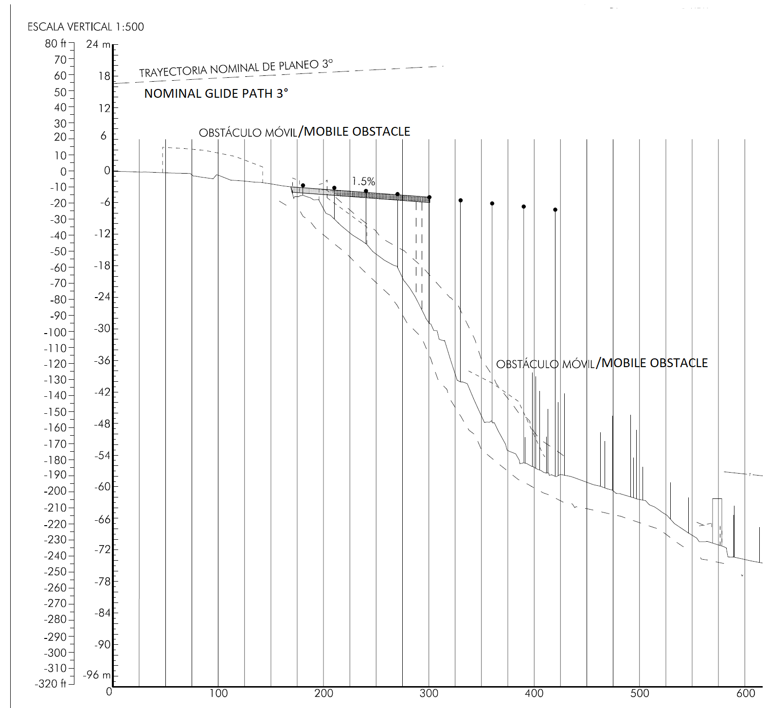
Figure 0: Typical example of ‘very complex’
with greater than 6 m ‘sea wall’ at 300 m (Asturias, LEAS 29 dated
2007) that after suitability assessment and due to the presence of ARAS, may be changed to ‘moderate’.
Example: A pre-threshold terrain with the following features would be
considered as ‘moderate’.
(1) Less
than 1 m variation of pre-threshold
terrain elevation from runway threshold elevation, in the area from runway
threshold up to 100 m prior to runway threshold
(2) Less
than 3 m variation of pre-threshold
terrain elevation from runway threshold elevation, in the area from 100 m prior to runway threshold up to 300 m prior to runway threshold
(2) Landing
system assessment area (LSAA) slope
Note: 600 metres after the threshold is the
standard length; however depending on the landing system, other lengths might
be relevant.
Although not recommended by ICAO Annex 14 Volume 1, slope variation in the LSAA can exist (refer to point 3.1.15 to point 3.1.18) and represent a factor of
risk to be considered. For the purpose of determining the relevant parameters
characterising slope and slope variation, the following definitions may be
used (Figure 1):
—
Mean LSAA slope: Slope computed from
runway threshold elevation up to runway elevation at 600 metres after the threshold.
—
Deviation from mean LSAA slope:
greatest elevation difference between any runway elevation inside LSAA and mean
LSAA slope.
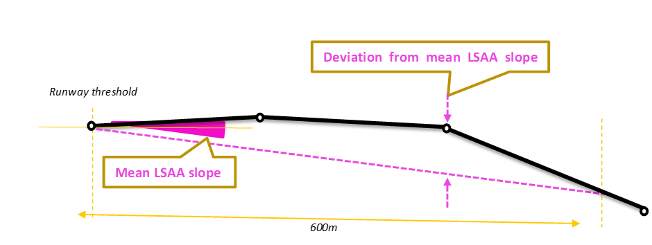
Figure 1: Mean LSAA
slope & Deviation from mean LSAA slope
Note: Published runway profiles usually contain the position and elevation
of each significant runway longitudinal slope change. Elevation at other
location can be interpolated assuming straight slope between each published
elevation. The highest/ lowest elevation of the LSAA might not be the one
where the deviation from mean LSAA slope is the greatest.
(i) Simple
(A) Approximately
+ 0.4 % mean LSAA slope and less than 1 m (3 ft)
variation around mean LSAA slope; or
(B) previous
experience in more constraining touch down condition in the same aircraft type
or variant.
(ii) Moderate
Approximately + 0.8 % mean
LSAA slope and less than 2 m (6 ft)
variation around mean LSAA slope.
(iii) Complex
Approximately + 1.0 % mean
LSAA slope and less than 4 m (12 ft)
variation around mean LSAA slope.
(iv) Very
complex
Outside any of the limits defined above.
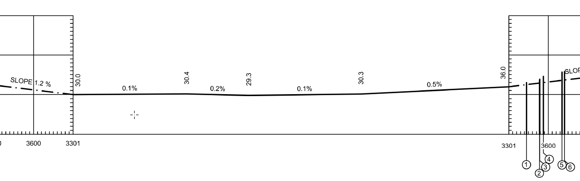
Figure 2: Typical example of ‘simple’
LSAA Slope (ESSA 01L dated 2018)
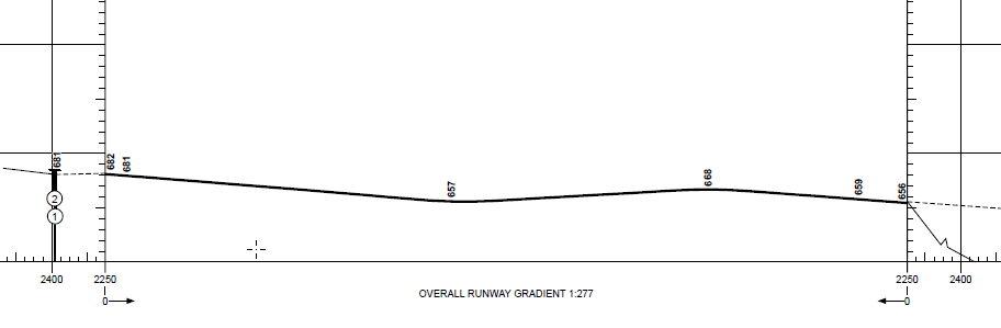
Figure 3: Typical example of ‘moderate’
LSAA slope due to variation around mean LSAA slope greater than 1 m but
lower than 2 m (EGNM 32 dated 2018)
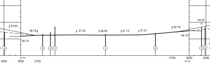
Figure 4: Typical example of ‘complex’
mean LSAA slope greater than 0.8 % but lower than 1 % (EDD 23L dated 2009)
(b) Operational
assessment programme: the following guidance provides examples of typical flight
programmes that can be used to demonstrate
suitability of a landing system using the operational assessment method,
considering the overall level of runway irregularities.
Note: For CAT II operations with no
use of autoland nor guidance for the flare manoeuvre, the programmes could be alleviated.
The flight programmes are expected to depend
on the level of runway irregularities. Table 1 provides examples of criteria
that can be used to determine the level of runway irregularities.
Table 1
Level of runway irregularities
to scale the flight programme
|
LSAA slope |
Simple |
Moderate |
Complex |
Very complex |
|
Simple |
Simple |
Moderate |
Complex |
Very complex |
|
Moderate |
Moderate |
Moderate |
Complex |
Very complex |
|
Complex |
Complex |
Complex |
Complex |
Very complex |
|
Very complex |
Very complex |
Very complex |
Very complex |
Very complex |
(1) Simple
runway
For simple runways, unless other factors can
be identified as a source of concern, no in-flight approach and landing may be
required.
(2) Moderate
runway
For moderate runways, a minimum of one
successful approach/landing using the procedures, equipment and operationally
relevant heights (DH/AH) for the intended operations is performed in the
meteorological conditions described in AMC1 SPA.LVO.110 Table 15. More approaches could be required if any issue is identified during
this approach/landing.
(3) Complex
runway
For complex runways, an initial minimum of
three approaches/landings using the procedures, equipment and operationally
relevant heights (DH/AH) for the intended operations is performed in the meteorological
conditions described in AMC1 SPA.LVO.110 Table 15, with at least one of the landings
close to the maximum landing weight for the intended operation and the other
two with other different conditions; for example, with a mid-weight in one and
low weight in another or with different wind conditions or aircraft
configuration flap full/flap 3, or a combination of them. The flights for the
assessment are conducted by pilots designated by the operator with defined
minimum experience and qualifications, with procedures defined for the purpose.
More approaches could be required if any issue is identified during these
approaches/landings.
For very complex runways, an initial minimum
of four to six approaches/landings using the procedures, equipment and
operationally relevant heights (DH/AH) for the intended operations is
performed in the meteorological conditions described in AMC1 SPA.LVO.110 Table 15 in typical aircraft weight conditions in flights with no commercial
passengers.
If no anomaly is observed after the first four
to six approaches/landings, extend the condition progressively close to the
maximum landing weight for the intended operation with at least 15 successful
approaches or landings and report any anomalies with the meteorological
conditions described in AMC1 SPA.LVO.110 Table 14 and with different conditions, for example with
different range of weight conditions (high, mid, low) or with different wind
conditions or aircraft configuration flap full/flap 3, or a combination of
them. The flights for the assessment should be conducted by pilots designated
by the operator with defined minimum experience and qualifications, with
procedures defined for the purpose.
(c) Operational assessment successful
criteria
(1) Data
to be recorded
To assess adequate performance of the landing
system, some form of quantitative data should be recorded and reviewed with the
competent authority as verification of performance. Acceptable methods of data
collection include but are not limited to:
(i) Record
of wind conditions and touch down point (can be observation).
(ii) Record
of pertinent landing system parameters (typically from a digital flight data
recorder, quick-access recorder or equivalent) with sufficient sampling rate
(typically higher than 1 sample per second) for the part of the flight
paths of interest (typically from 300 ft height above touch down through
de-rotation after touch down) including typically:
—
barometric altitude;
—
radio altitude;
—
glide path error;
—
vertical speed;
—
elevator command;
—
pitch attitude;
—
throttle position/thrust commanded;
—
airspeed;
—
mode transition or engagement.
(iii) Photo
or video recording of pertinent instrument or instrument and outside view
allowing post-flight replay and review of the above parameters.
(2) Data
review and analysis to assess acceptable performance
The final approach, flare and touch down
profile should be reviewed with the competent authority to ensure suitability
of at least each of the following:
(i) suitability
of the resulting flight path;
(ii) acceptability
of any flight path deviation from the nominal path (e.g. glide path deviation,
deviation from nominal flare profile);
(iii) proper
mode switching;
(iv) suitable
touch down point;
(v) suitable
sink rate at touch down;
(vi) proper
flare initiation altitude;
(vii) suitability
flare quality (e.g. no evidence of early or late flare, no over-flare or under
flare, no undue ‘pitch down’ tendency at flare initiation or during flare, no
flare oscillation, no abrupt flare, no inappropriate pitch response during
flare, no unacceptable floating tendency, or other unacceptable characteristic
that a pilot could interpret as a failure or inappropriate response of the
landing system);
(viii) no
unusual flight control displacement (e.g. elevator control input spikes or
oscillation);
(ix) appropriate
throttle/thrust retard (e.g. no early or late retard, no failure to retard, no
undue reversal of retard, no undue pitch/thrust coupling);
(x) appropriate
speed decay in flare (e.g. no unusually low speed risking high pitch attitude
and tail strike, no excessive float, appropriate seed decay even if well above
Vref at flare initiation due to planned wind or gust compensation);
(xi) proper
mode initiation or mode transition relating to altitude or radio altitude
inputs (e.g. crosswind alignment).