CS ADR-DSN.M.655 Obstacle
protection surface for PAPI and APAPI
ED Decision 2022/006/R
(a) Applicability:
An obstacle protection surface should be established when it is intended to provide a visual approach slope indicator system.
(b) Characteristics:
The characteristics of the obstacle protection surface, i.e. origin, divergence, length, and slope should correspond to those specified in the relevant column of Table M-2 and in Figure M-6.
(c) New objects or extensions of existing objects should not be permitted above an obstacle protection surface except when the new object or extension would be shielded by an existing immovable object, or if after a safety assessment, it is determined that the object would not adversely affect the safety of operations of aeroplanes.
(d) Where a safety assessment indicates that an existing object extending above an obstacle protection surface could adversely affect the safety of operations of aeroplanes one or more of the following measures should be taken:
(1) remove
the object;
(2) suitably
raise the approach slope of the system;
(3) reduce
the azimuth spread of the system so that the object is outside the confines of
the beam;
(4) displace
the axis of the system and its associated obstacle protection surface by no
more than 5°;
(5) suitably
displace the threshold; and
(6) where (5) is found to be impracticable,
suitably displace the system upwind of the threshold such that the object no
longer penetrates the obstacle protection surface.
|
Runway type/code number |
||||||||
|
Non-instrument |
Instrument |
|||||||
|
Code number |
Code number |
|||||||
|
Surface
dimensions |
1 |
2 |
3 |
4 |
1 |
2 |
3 |
4 |
|
Length of inner edge |
60 m |
80 m |
150 m |
150 m |
150 m |
150 m |
300 m |
300 m |
|
Distance from the visual approach slope indicator system2 |
D1+30 m |
D1+60 m |
D1+60 m |
D1+60 m |
D1+60 m |
D1+60 m |
D1+60 m |
D1+60 m |
|
Divergence (each side) |
10 % |
10 % |
10 % |
10 % |
15 % |
15 % |
15 % |
15 % |
|
Total length |
7 500 m |
7 500 m |
15 000 m |
15 000 m |
7 500 m |
7 500 m |
15 000 m |
15 000 m |
|
Slope |
|
|
|
|
|
|
|
|
|
a) PAPI1 |
― |
A–0.57° |
A–0.57° |
A–0.57° |
A–0.57° |
A–0.57° |
A–0.57° |
A–0.57° |
|
b) APAPI1 |
A–0.9° |
A–0.9° |
– |
– |
A–0.9° |
A–0.9° |
– |
– |
|
1Angles as indicated in Figure M-5. 2 D1 is the
distance of the visual approach slope indicator system from threshold prior
to any displacement to remedy object penetration of the obstacle protection
surface (refer to Figure M-4). The start of the obstacle protection surface
is fixed to the visual approach slope indicator system location, such that
displacement of the PAPI results in an equal displacement of the start of
the obstacle protection surface. |
||||||||
Table M-2.
Dimensions and slopes of the obstacle protection surface
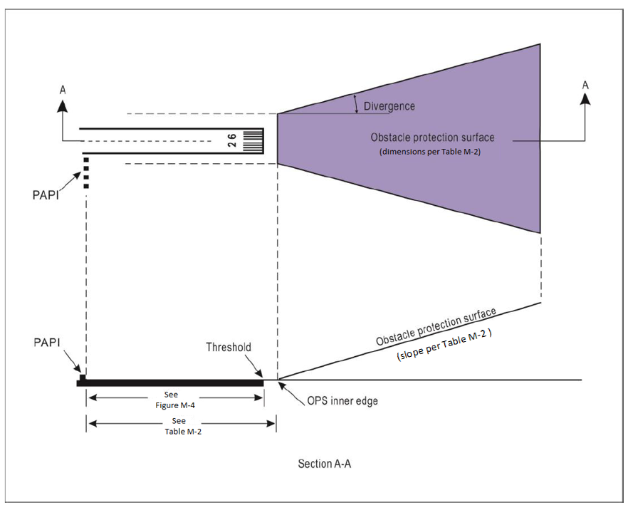
Figure M-6.
Obstacle protection surface for visual approach slope indicator systems
[Issue: ADR-DSN/3]
[Issue: ADR-DSN/4]
[Issue: ADR-DSN/6]