ED Decision 2003/18/RM
(a) General. Each design condition in subparagraphs (b) and (c) of this paragraph must be used to assure sufficient strength for each condition of speed and load factor on or within the boundary of a V-n diagram for the aeroplane similar to the diagram in figure A3 of this Appendix. This diagram must also be used to determine the aeroplane structural operating limitations as specified in CS-VLA 1501(c) to 1511 and 1519.
(b) Symmetrical flight conditions. The aeroplane must be designed for symmetrical flight conditions as follows:
(1) The aeroplane must be designed for at least the four basic flight conditions, ‘A’, ‘D’, ‘E‘, and ‘G‘ as noted on the flight envelope of figure A3 of this Appendix. In addition, the following requirements apply:
(i) The design limit flight load factors corresponding to conditions ‘D’ and ‘E’ of figure A3 must be at least as great as those specified in Table 1 and figure A3 of this Appendix, and the design speed for these conditions must be at least equal to the value of VDmin found from Table 3 of this Appendix.
(ii) For conditions ‘A’ and ‘G‘ of figure A3, the load factors must correspond to those specified in Table 1 of this Appendix, and the design speeds must be computed using these load factors with the maximum static life coefficient CNA determined by the applicant. However, in the absence of more precise computations, these latter conditions may be based on a value of CNA = ±35 and the design speed for condition ‘A’ may be less than VAmin.
(iii) Conditions ‘C‘ and ‘F‘ of figure A3 need only be investigated when n3 W/S or n4 W/S are greater than n1 W/S or n2 W/S of this Appendix, respectively. The use of figures A1 and A2 for points ‘C’ and ‘F’ is restricted to wings of Aspect Ratio of 7 or less. In other cases, the method of CS-VLA 341 should be used.
(2) If flaps or other high lift devices intended for use at the relatively low airspeed of approach, landing, and take-off, are installed, the aeroplane must be designed for the two flight conditions corresponding to the values of limit flap-down factors specified in Table 1 of this Appendix with the flaps fully extended at not less than the design flap speed VFmin from Table 3 of this Appendix.
(c) Unsymmetrical flight conditions. Each affected structure must be designed for unsymmetrical loadings as follows:
(1) The aft fuselage-to-wing attachment must be designed for the critical vertical surface load determined in accordance with sub-paragraphs A11(c)(1) and (2) of this Appendix.
(2) The wing and wing carry-through structures must be designed for 100% of condition ‘A’ loading on one side of the plane of symmetry and 70% on the opposite side.
(3) The wing and wing carry-through structures must be designed for the loads resulting from a combination of 75% of the positive manoeuvring wing loading on both sides of the plane of symmetry and the maximum wing torsion resulting from aileron displacement. The effect of aileron displacement on wing torsion at VC or VA using the basic aerofoil moment coefficient, Cmo, modified over the aileron portion of the span, must be computed as follows:
(i) Cm = Cmo + 0.01 δu (up aileron side) wing basic aerofoil.
(ii) Cm = Cmo - 0.01 δd (down aileron side) wing basic aerofoil, where δu is the up aileron deflection and δd is the down aileron.
(4) ∆ critical, which is the sum of δu + δd, must be computed as follows:
(i) Compute ∆a and ∆b from the formulae -

and

VD where ∆p = the maximum total deflection (sum of both aileron deflections) at VA with VA, VC, and VD described in sub-paragraph (2) of A7(e) of this Appendix.
(ii) Compute K from the formula -
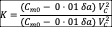
where δa is the down aileron deflection corresponding to ∆a and δb is the down aileron deflection corresponding to ∆b as computed in step (i).
(iii) If K is less than 1.0, ∆ a is ∆ critical and must be used to determine δu, and δd. In this case, VC is the critical speed which must be used in computing the wing torsion loads over the aileron span.
(iv) If K is equal to or greater than 1.0, ∆b is ∆ critical and must be used to determine δu and δd. In this case, VD is the critical speed which must be used in computing the wing torsion loads over the aileron span.
(d) Supplementary conditions; rear lift truss; engine torque; side load on engine mount. Each of the following supplementary conditions must be investigated:
(1) In designing the rear lift truss, the special condition specified in CS-VLA 369 may be investigated instead of condition ‘G’ of figure A3 of this Appendix.
(2) The engine mount and its supporting structure must be designed for the maximum limit torque corresponding to Maximum Expected Take-off Power and propeller speed acting simultaneously with the limit loads resulting from the maximum positive manoeuvring flight load factor n1. The limit torque must be obtained by multiplying the mean torque by the factor defined in CS-VLA 361(b).
(3) The engine mount and its supporting structure must be designed for the loads resulting from a lateral limit load factor of not less than 1.47.