Part VI – Test Method to
Determine the Flammability and Flame Propagation Characteristics of
Thermal/Acoustic Insulation Materials
ED Decision 2009/010/R
Use this test method to evaluate the flammability and flame propagation characteristics of thermal/acoustic insulation when exposed to both a radiant heat source and a flame.
(a) Definitions.
‘‘Flame propagation’’ means the furthest distance of the propagation of visible flame towards the far end of the test specimen, measured from the midpoint of the ignition source flame. Measure this distance after initially applying the ignition source and before all flame on the test specimen is extinguished. The measurement is not a determination of burn length made after the test.
‘‘Radiant heat source’’ means an electric or air propane panel.
‘‘Thermal/acoustic insulation’’ means a material or system of materials used to provide thermal and/or acoustic protection. Examples include fibreglass or other batting material encapsulated by a film covering and foams.
‘‘Zero point’’ means the point of application of the pilot burner to the test specimen.
(b) Test apparatus.
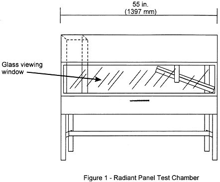
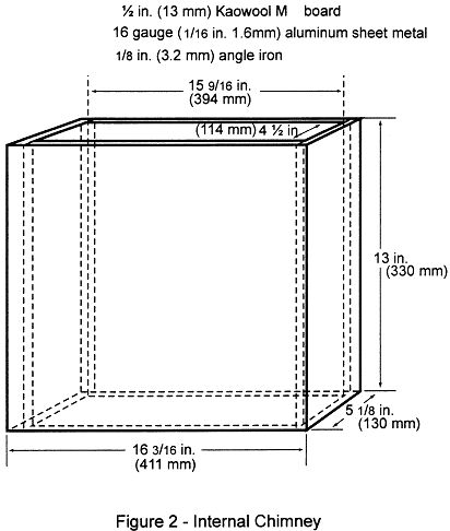
(1) Radiant panel test chamber. Conduct tests in a radiant panel test chamber (see figure 1 above). Place the test chamber under an exhaust hood to facilitate clearing the chamber of smoke after each test. The radiant panel test chamber must be an enclosure 1397 mm (55 inches) long by 495 mm (19.5 inches) deep by 710 mm (28 inches) to 762 mm (maximum) (30 inches) above the test specimen. Insulate the sides, ends, and top with a fibrous ceramic insulation, such as Kaowool MTM board. On the front side, provide a 52 by 12-inch (1321 by 305 mm) draft-free, high-temperature, glass window for viewing the sample during testing. Place a door below the window to provide access to the movable specimen platform holder. The bottom of the test chamber must be a sliding steel platform that has provision for securing the test specimen holder in a fixed and level position. The chamber must have an internal chimney with exterior dimensions of 129 mm (5.1 inches) wide, by 411 mm (16.2 inches) deep by 330 mm (13 inches) high at the opposite end of the chamber from the radiant energy source. The interior dimensions must be 114 mm (4.5 inches) wide by 395 mm (15.6 inches) deep. The chimney must extend to the top of the chamber (see figure 2).
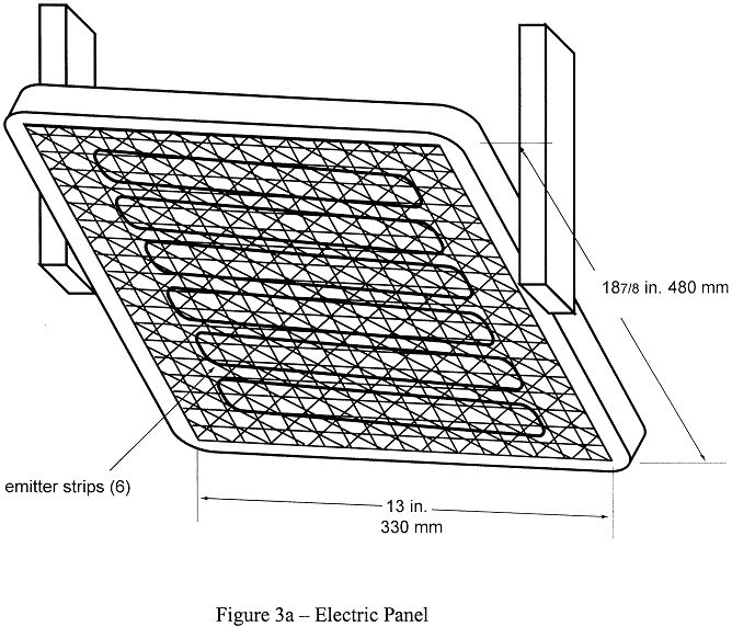
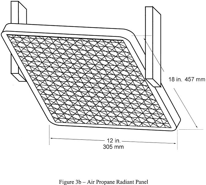
(2) Radiant heat source. Mount the radiant heat energy source in a cast iron frame or equivalent. An electric panel must have six, 76 mm (3-inch) wide emitter strips. The emitter strips must be perpendicular to the length of the panel. The panel must have a radiation surface of 327 by 470 mm (12⅞ by 18½ inches). The panel must be capable of operating at temperatures up to 704°C (1300°F). An air propane panel must be made of a porous refractory material and have a radiation surface of 305 by 457 mm (12 by 18 inches). The panel must be capable of operating at temperatures up to 816°C (1500°F). See figures 3a and 3b.
(i) Electric radiant panel. The radiant panel must be 3-phase and operate at 208 volts. A single-phase, 240 volt panel is also acceptable. Use a solid-state power controller and microprocessor-based controller to set the electric panel operating parameters.
(ii) Gas radiant panel. Use propane (liquid petroleum gas—2.1 UN 1075) for the radiant panel fuel. The panel fuel system must consist of a venturi-type aspirator for mixing gas and air at approximately atmospheric pressure. Provide suitable instrumentation for monitoring and controlling the flow of fuel and air to the panel. Include an air flow gauge, an air flow regulator, and a gas pressure gauge.
(iii) Radiant panel placement. Mount the panel in the chamber at 30° to the horizontal specimen plane, and 19 cm (7 ½ inches) above the zero point of the specimen.
(3) Specimen holding system.
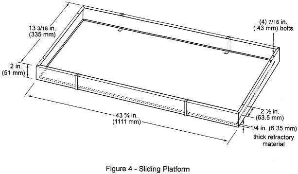
(i) The sliding platform serves as the housing for test specimen placement. Brackets may be attached (via wing nuts) to the top lip of the platform in order to accommodate various thicknesses of test specimens. Place the test specimens on a sheet of Kaowool MTM board or 1260 Standard Board (manufactured by Thermal Ceramics and available in Europe) or equivalent, either resting on the bottom lip of the sliding platform or on the base of the brackets. It may be necessary to use multiple sheets of material based on the thickness of the test specimen (to meet the sample height requirement). Typically, these non-combustible sheets of material are available in 6 mm (¼ inch) thicknesses. See figure 4. A sliding platform that is deeper than the 50.8 mm (2-inch) platform shown in figure 4 is also acceptable as long as the sample height requirement is met.
(ii) Attach a 13 mm (½ inch) piece of Kaowool MTM board or other high temperature material measuring 1054 by 210 mm (41½ by 8¼ inches) to the back of the platform. This board serves as a heat retainer and protects the test specimen from excessive preheating. The height of this board must not impede the sliding platform movement (in and out of the test chamber). If the platform has been fabricated such that the back side of the platform is high enough to prevent excess preheating of the specimen when the sliding platform is out, a retainer board is not necessary.
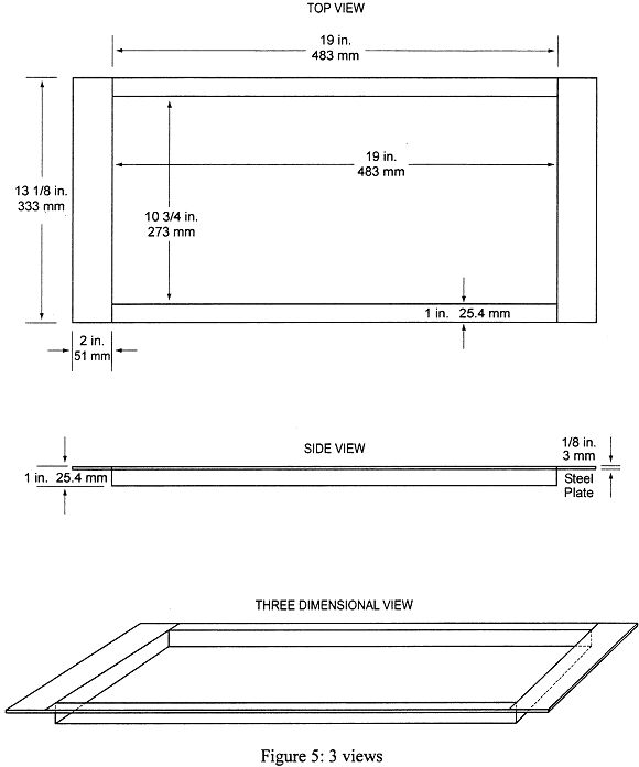
(iii) Place the test specimen horizontally on the non-combustible board(s). Place a steel retaining/securing frame fabricated of mild steel, having a thickness of 3.2 mm (⅛ inch) and overall dimensions of 584 by 333 mm (23 by 13⅛ inches) with a specimen opening of 483 by 273 mm (19 by 10¾ inches) over the test specimen. The front, back, and right portions of the top flange of the frame must rest on the top of the sliding platform, and the bottom flanges must pinch all 4 sides of the test specimen. The right bottom flange must be flush with the sliding platform. See figure 5.
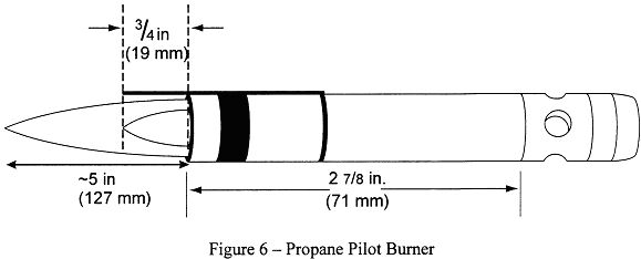
(4) Pilot Burner. The pilot burner used to ignite the specimen must be a BernzomaticTM (or equivalent) commercial propane venturi torch with an axially symmetric burner tip and a propane supply tube with an orifice diameter of 0.15 mm (0.006 inches). The length of the burner tube must be 71 mm (2⅞ inches). The propane flow must be adjusted via gas pressure through an in-line regulator to produce a blue inner cone length of 19 mm (¾ inch) . A 19 mm (¾ inch) guide (such as a thin strip of metal) may be soldered to the top of the burner to aid in setting the flame height. The overall flame length must be approximately 127 mm (5 inches) long. Provide a way to move the burner out of the ignition position so that the flame is horizontal and at least 50 mm (2 inches) above the specimen plane. See figure 6.
(5) Thermocouples. Install a 24 American Wire Gauge (AWG) Type K (Chromel-Alumel) thermocouple in the test chamber for temperature monitoring. Insert it into the chamber through a small hole drilled through the back of the chamber. Place the thermocouple so that it extends 279 mm (11 inches) out from the back of the chamber wall, 292 mm (11½ inches) from the right side of the chamber wall, and is 51 mm (2 inches) below the radiant panel. The use of other thermocouples is optional.
(6) Calorimeter. The calorimeter must be a one-inch cylindrical water-cooled, total heat flux density, foil type Gardon Gage that has a range of 0 to 5.7 Watts/cm2 (0 to 5 BTU/ft2 sec).
(7) Calorimeter calibration specification and procedure.
(i) Calorimeter specification.
(A) Foil diameter must be 6.35 ± 0.13 mm (0.25 ± 0.005 inches).
(B) Foil thickness must be 0.013 ± 0.0025 mm (0.0005 ± 0.0001 inches).
(C) Foil material must be thermocouple grade Constantan.
(D) Temperature measurement must be a Copper Constantan thermocouple.
(E) The copper center wire diameter must be 0.013 mm (0.0005 inches).
(F) The entire face of the calorimeter must be lightly coated with ‘‘Black Velvet’’ paint having an emissivity of 96 or greater.
(ii) Calorimeter calibration.
(A) The calibration method must be by comparison to a like standardized transducer.
(B) The standardized transducer must meet the specifications given in paragraph (b)(6) of Part VI of this Appendix.
(C) Calibrate the standard transducer against a primary standard traceable to the National Institute of Standards and Technology (NIST).
(D) The method of transfer must be a heated graphite plate.
(E) The graphite plate must be electrically heated, have a clear surface area on each side of the plate of at least 51 by 51 mm (2 by 2 inches), and be 3.2 ± 1.6 mm (⅛± 1⁄16 inch) thick.
(F) enter the 2 transducers on opposite sides of the plates at equal distances from the plate.
(G) The distance of the calorimeter to the plate must be no less than 1.6 mm (0.0625 inches), nor greater than 9.5 mm (0.375 inches).
(H) The range used in calibration must be at least 0–3.9 Watts/cm2 (0–3.5 BTUs/ft2 sec) and no greater than 0–6.4 Watts/cm2 (0–5.7 BTUs/ft2 sec).
(I) The recording device used must record the 2 transducers simultaneously or at least within 1⁄10 of each other.
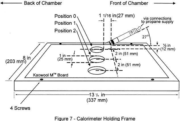
(8) Calorimeter fixture. With the sliding platform pulled out of the chamber, install the calorimeter holding frame and place a sheet of non-combustible material in the bottom of the sliding platform adjacent to the holding frame. This will prevent heat losses during calibration. The frame must be 333 mm (13⅛ inches) deep (front to back) by 203 mm (8 inches) wide and must rest on the top of the sliding platform. It must be fabricated of 3.2 mm (⅛ inch) flat stock steel and have an opening that accommodates a 12.7 mm (½ inch) thick piece of refractory board, which is level with the top of the sliding platform. The board must have three 25.4 mm (1 inch) diameter holes drilled through the board for calorimeter insertion. The distance to the radiant panel surface from the centreline of the first hole (‘‘zero’’ position) must be 191 ± 3 mm (7½ ± ⅛ inches). The distance between the centreline of the first hole to the centreline of the second hole must be 51 mm (2 inches). It must also be the same distance from the centreline of the second hole to the centreline of the third hole. See figure 7. A calorimeter holding frame that differs in construction is acceptable as long as the height from the centreline of the first hole to the radiant panel and the distance between holes is the same as described in this paragraph.
(9) Instrumentation. Provide a calibrated recording device with an appropriate range or a computerized data acquisition system to measure and record the outputs of the calorimeter and the thermocouple. The data acquisition system must be capable of recording the calorimeter output every second during calibration.
(10) Timing device. Provide a stopwatch or other device, accurate to ± 1 second/hour, to measure the time of application of the pilot burner flame.
(c) Test specimens.
(1) Specimen preparation. Prepare and test a minimum of three test specimens. If an oriented film cover material is used, prepare and test both the warp and fill directions.
(2) Construction. Test specimens must include all materials used in construction of the insulation (including batting, film, scrim, tape etc.). Cut a piece of core material such as foam or fiberglass, and cut a piece of film cover material (if used) large enough to cover the core material. Heat sealing is the preferred method of preparing fiberglass samples, since they can be made without compressing the fiberglass (‘‘box sample’’). Cover materials that are not heat sealable may be stapled, sewn, or taped as long as the cover material is over-cut enough to be drawn down the sides without compressing the core material. The fastening means should be as continuous as possible along the length of the seams. The specimen thickness must be of the same thickness as installed in the airplane.
(3) Specimen Dimensions. To facilitate proper placement of specimens in the sliding platform housing, cut non-rigid core materials, such as fibreglass, 318 mm (12½ inches) wide by 584 mm (23 inches) long. Cut rigid materials, such as foam, 292 ± 6 mm (11½ ± ¼ inches) wide by 584 mm (23 inches) long in order to fit properly in the sliding platform housing and provide a flat, exposed surface equal to the opening in the housing.
(d) Specimen conditioning. Condition the test specimens at 21 ± 2°C (70 ± 5°F) and 55% ± 10% relative humidity, for a minimum of 24 hours prior to testing.
(e) Apparatus Calibration.
(1) With the sliding platform out of the chamber, install the calorimeter holding frame. Push the platform back into the chamber and insert the calorimeter into the first hole (‘‘zero’’ position). See figure 7. Close the bottom door located below the sliding platform. The distance from the centerline of the calorimeter to the radiant panel surface at this point must be 191 ± 3 mm (7½ ± ⅛ inches). Prior to igniting the radiant panel, ensure that the calorimeter face is clean and that there is water running through the calorimeter.
(2) Ignite the panel. Adjust the fuel/air mixture to achieve 1.7 Watts/cm2 ± 5% (1.5 BTUs/ft2 sec ± 5%) at the ‘‘zero’’ position. If using an electric panel, set the power controller to achieve the proper heat flux. Allow the unit to reach steady state (this may take up to 1 hour). The pilot burner must be off and in the down position during this time.
(3) After steady-state conditions have been reached, move the calorimeter 51 mm (2 inches) from the ‘‘zero’’ position (first hole) to position 1 and record the heat flux. Move the calorimeter to position 2 and record the heat flux. Allow enough time at each position for the calorimeter to stabilize. Table 1 depicts typical calibration values at the three positions.
TABLE
1.—CALIBRATION TABLE
|
Position |
BTU’s/ft2 sec |
Watts/cm2 |
|
‘‘Zero’’ Position. |
1.5 |
1.7 |
|
Position 1 |
1.51–1.50–1.49 |
1.71–1.70–1.69 |
|
Position 2 |
1.43–1.44 |
1.62–1.63 |
(4) Open the bottom door. Remove the calorimeter and holder fixture. Use caution as the fixture is very hot.
(f) Test Procedure.
(1) Ignite the pilot burner. Ensure that it is at least 51 mm (2 inches) above the top of the platform. The burner must not contact the specimen until the test begins.
(2) Place the test specimen in the sliding platform holder. Ensure that the test sample surface is level with the top of the platform. At ‘‘zero’’ point, the specimen surface must be 191 ± 3 mm (7 ½ ± ⅛ inches) below the radiant panel.
(3) Place the retaining/securing frame over the test specimen. It may be necessary (due to compression) to adjust the sample (up or down) in order to maintain the distance from the sample to the radiant panel 191 ± 3 mm (7½ ± ⅛ inches) at ‘‘zero’’ position). With film/fiberglass assemblies, it is critical to make a slit in the film cover to purge any air inside. This allows the operator to maintain the proper test specimen position (level with the top of the platform) and to allow ventilation of gases during testing. A longitudinal slit, approximately 2 inches (51 mm) in length, must be centered 76 ± 13 mm (3 ± ½ inches) from the left flange of the securing frame. A utility knife is acceptable for slitting the film cover.
(4) Immediately push the sliding platform into the chamber and close the bottom door.
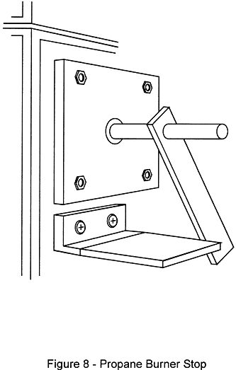
(5) Bring the pilot burner flame into contact with the center of the specimen at the ‘‘zero’’ point and simultaneously start the timer. The pilot burner must be at a 27° angle with the sample and be approximately ½ inch (12 mm) above the sample. See figure 7. A stop, as shown in figure 8, allows the operator to position the burner correctly each time.
(6) Leave the burner in position for 15 seconds and then remove to a position at least 51 mm (2 inches) above the specimen.
(g) Report.
(1) Identify and describe the test specimen.
(2) Report any shrinkage or melting of the test specimen.
(3) Report the flame propagation distance. If this distance is less than 51 mm (2 inches), report this as a pass (no measurement required).
(4) Report the after-flame time.
(h) Requirements.
(1) There must be no flame propagation beyond 51 mm (2 inches) to the left of the centerline of the pilot flame application.
(2) The flame time after removal of the pilot burner may not exceed 3 seconds on any specimen.
[Amdt 25/6]