Part VII – Test Method to Determine the Burnthrough Resistance of
Thermal/Acoustic Insulation Materials
ED Decision 2009/010/R
Use the following test method to evaluate the burnthrough resistance characteristics of aircraft thermal/acoustic insulation materials when exposed to a high intensity open flame.
(a) Definitions.
Burnthrough time means the time, in seconds, for the burner flame to penetrate the test specimen, and/or the time required for the heat flux to reach 2.27 W/cm2 (2.0 Btu/ft2 sec) on the inboard side, at a distance of 30.5 cm (12 inches) from the front surface of the insulation blanket test frame, whichever is sooner. The burnthrough time is measured at the inboard side of each of the insulation blanket specimens.
Insulation blanket specimen means one of two specimens positioned in either side of the test rig, at an angle of 30° with respect to vertical.
Specimen set means two insulation blanket specimens. Both specimens must represent the same production insulation blanket construction and materials, proportioned to correspond to the specimen size.
(b) Apparatus.
(1) The arrangement of the test apparatus is shown in figures 1 and 2 and must include the capability of swinging the burner away from the test specimen during warm-up.
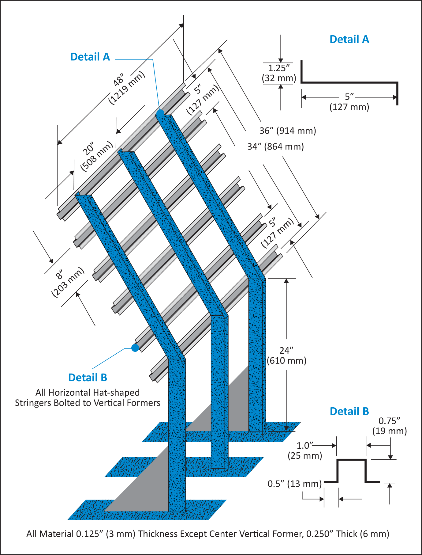
Figure 1 –
Burnthrough Test Apparatus Specimen Holder
(2) Test
burner. The test burner must be a modified gun-type such as the Park Model DPL
3400 or equivalent. Flame characteristics are highly dependent on actual
burner setup. Parameters such as fuel pressure, nozzle depth, stator position,
and intake airflow must be properly adjusted to achieve the correct flame
output.
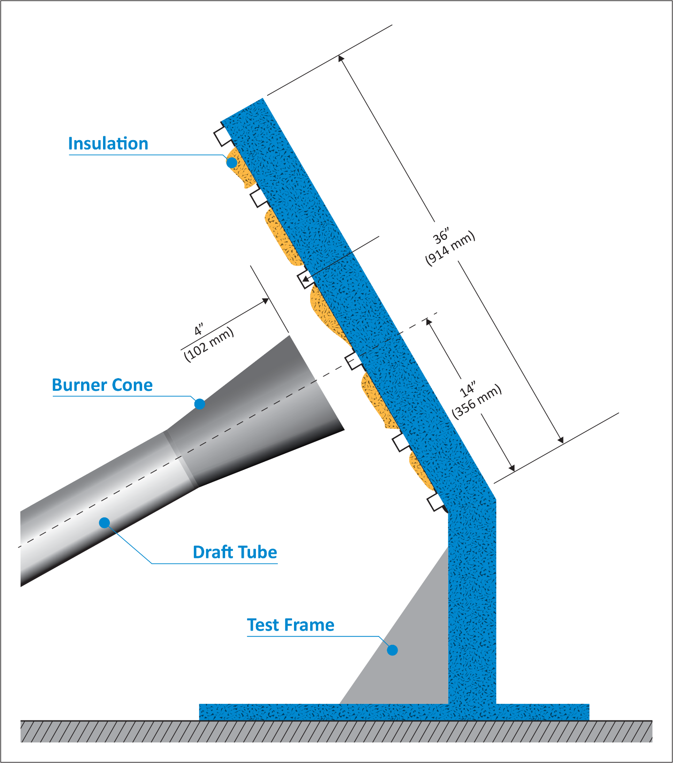
Figure 2 –
Burnthrough Test Apparatus
(i) Nozzle. A nozzle must maintain the fuel pressure to yield a nominal 0.378 l/min (6.0 gal/hr) fuel flow. A Monarch-manufactured 80° PL (hollow cone) nozzle nominally rated at 6.0 gal/hr at 100 lb/in2 (0.71 MPa) delivers a proper spray pattern.
(ii) Fuel Rail. The fuel rail must be adjusted to position the fuel nozzle at a depth of 8 mm (0.3125 inch) from the end plane of the exit stator, which must be mounted in the end of the draft tube.
(iii) Internal Stator. The internal stator, located in the middle of the draft tube, must be positioned at a depth of 95 mm (3.75 inches) from the tip of the fuel nozzle. The stator must also be positioned such that the integral igniters are located at an angle midway between the 10 and 11 o’clock position, when viewed looking into the draft tube. Minor deviations to the igniter angle are acceptable if the temperature and heat flux requirements conform to the requirements of paragraph (e) of Part VII of this Appendix.
(iv) Blower Fan. The cylindrical blower fan used to pump air through the burner must measure 133 mm (5.25 inches) in diameter by 89 mm (3.5 inches) in width.
(v) Burner cone. Install a 305 ± 3-mm (12 ± 0.125-inch) burner extension cone at the end of the draft tube. The cone must have an opening 152 ± 3 mm (6 ± 0.125 inches) high and 280 ± 3 mm (11 ± 0.125 inches) wide (see figure 3).
(vi) Fuel. Use JP–8, Jet A, or their international equivalent, at a flow rate of 0.378 ± 0.0126 l/min (6.0 ± 0.2 gal/hr). If this fuel is unavailable, ASTM K2 fuel (Number 2 grade kerosene) or ASTM D2 fuel (Number 2 grade fuel oil or Number 2 diesel fuel) are acceptable if the nominal fuel flow rate, temperature, and heat flux measurements conform to the requirements of paragraph (e) of Part VII of this Appendix.
(vii) Fuel pressure regulator. Provide a fuel pressure regulator, adjusted to deliver a nominal 0.378 l/min (6.0 gal/hr) flow rate. An operating fuel pressure of 0.71 MPa (100 lb/in2) for a nominally rated 6.0 gal/hr 80° spray angle nozzle (such as a PL type) delivers 0.378 ± 0.0126 l/ min (6.0 ± 0.2 gal/hr).
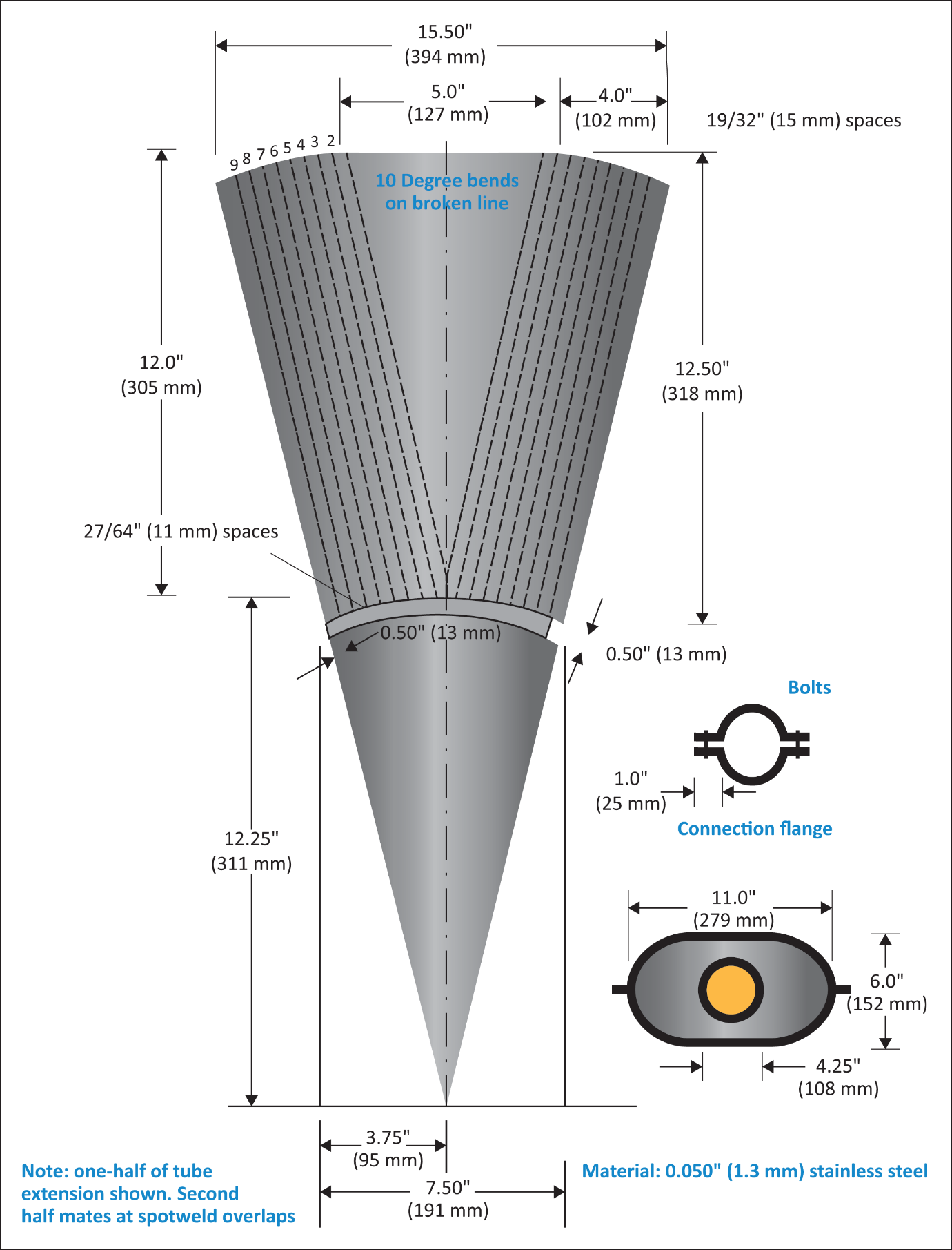
Figure 3 – Burner
Draft Tube Extension Cone Diagram
(3) Calibration rig and equipment.
(i) Construct individual calibration rigs to incorporate a calorimeter and thermocouple rake for the measurement of heat flux and temperature. Position the calibration rigs to allow movement of the burner from the test rig position to either the heat flux or temperature position with minimal difficulty.
(ii) Calorimeter. The calorimeter must be a total heat flux, foil type Gardon Gage of an appropriate range such as 0–22.7 W/cm2 (0–20 Btu/ft2 sec), accurate to ± 3% of the indicated reading. The heat flux calibration method must be in accordance with paragraph (b)(7) of Part VI of this Appendix.
(iii) Calorimeter mounting. Mount the calorimeter in a 152 by 305 ± 3 mm (6 by 12 ± 0.125 inches) by 19 ± 3 mm (0.75 ± 0.125 inches) thick insulating block which is attached to the heat flux calibration rig during calibration (figure 4). Monitor the insulating block for deterioration and replace it when necessary. Adjust the mounting as necessary to ensure that the calorimeter face is parallel to the exit plane of the test burner cone.
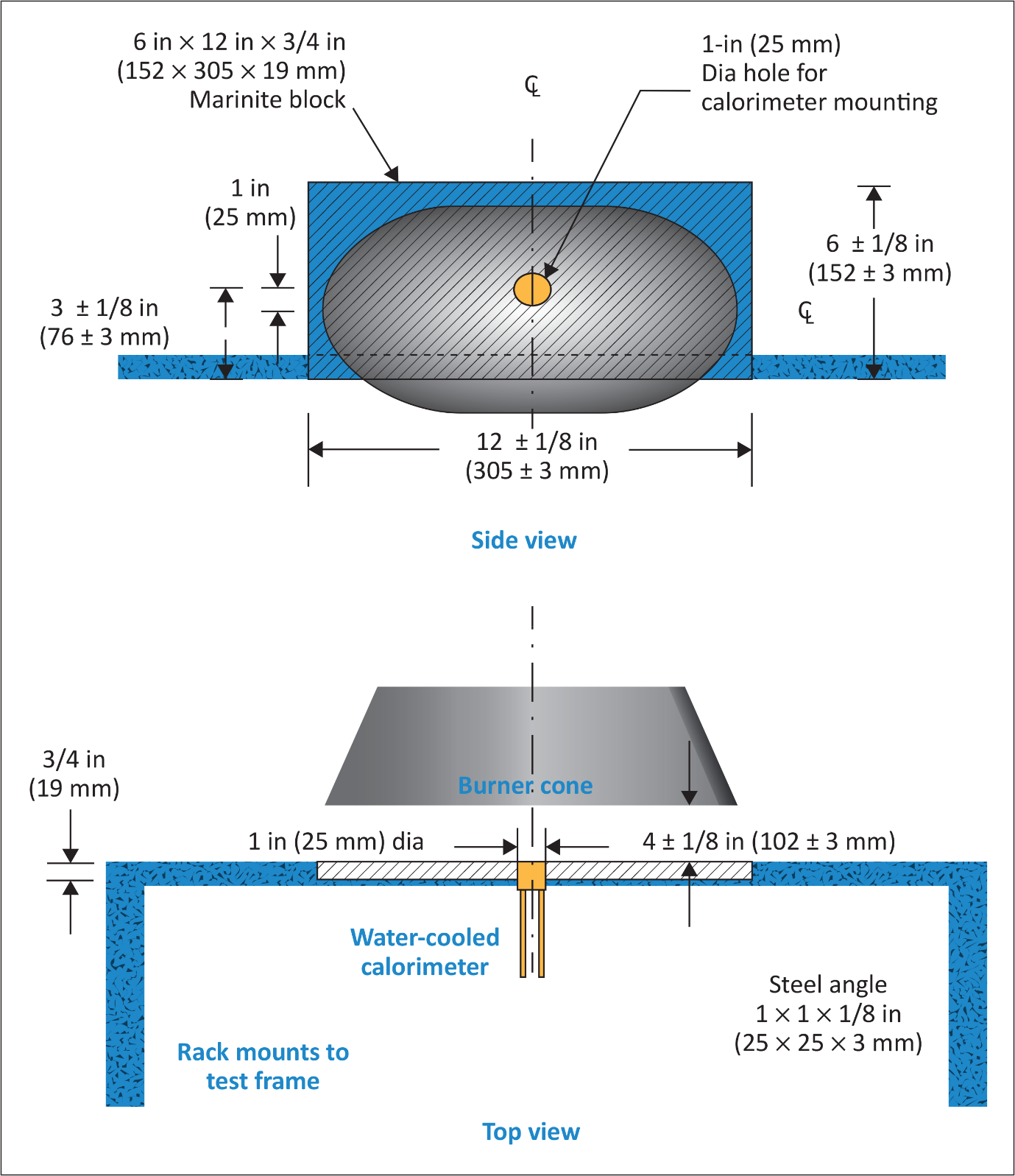
Figure 4 –
Calorimeter Position Relative to Burner Cone
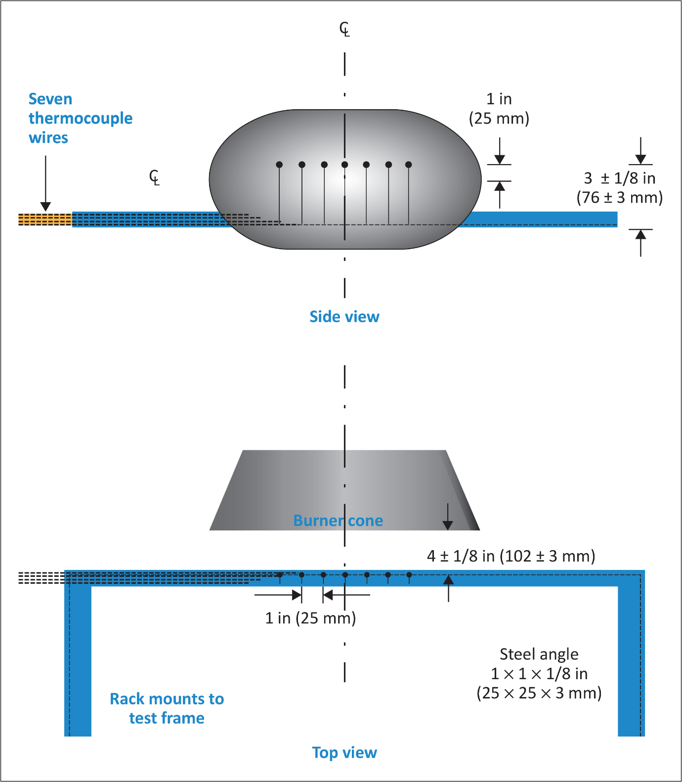
Figure 5 –
Thermocouple Rake Position Relative to Burner Cone
(iv) Thermocouples. Provide seven 3.2 mm (⅛-inch) ceramic packed, metal sheathed, type K (Chromel-alumel), grounded junction thermocouples with a nominal 24 American Wire Gauge (AWG) size conductor for calibration. Attach the thermocouples to a steel angle bracket to form a thermocouple rake for placement in the calibration rig during burner calibration (figure 5).
(v) Air velocity meter. Use a vane-type air velocity meter to calibrate the velocity of air entering the burner. An Omega Engineering Model HH30A or equivalent is satisfactory. Use a suitable adapter to attach the measuring device to the inlet side of the burner to prevent air from entering the burner other than through the measuring device, which would produce erroneously low readings. Use a flexible duct, measuring 102 mm (4 inches) wide by 6.1 meters (20 feet) long, to supply fresh air to the burner intake to prevent damage to the air velocity meter from ingested soot. An optional airbox permanently mounted to the burner intake area can effectively house the air velocity meter and provide a mounting port for the flexible intake duct.
(4) Test specimen mounting frame. Make the mounting frame for the test specimens of 3.2 mm (⅛-inch) thick steel as shown in figure 1, except for the centre vertical former, which should be 6.4 mm (¼-inch) thick to minimize warpage. The specimen mounting frame stringers (horizontal) should be bolted to the test frame formers (vertical) such that the expansion of the stringers will not cause the entire structure to warp. Use the mounting frame for mounting the two insulation blanket test specimens as shown in figure 2.
(5) Backface calorimeters. Mount two total heat flux Gardon type calorimeters behind the insulation test specimens on the back side (cold) area of the test specimen mounting frame as shown in figure 6. Position the calorimeters along the same plane as the burner cone centreline, at a distance of 102 mm (4 inches) from the vertical centreline of the test frame.
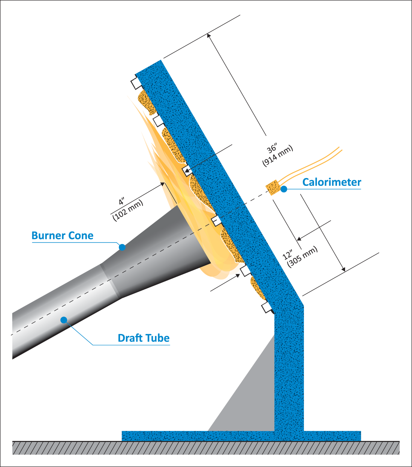
Figure 6 –
Position of Backface Calorimeters Relative to Test Specimen Frame
(i) The calorimeters must be a total heat flux, foil type Gardon Gage of an appropriate range such as 0–5.7 W/cm2 (0–5 Btu/ft2 sec), accurate to ± 3% of the indicated reading. The heat flux calibration method must comply with paragraph (b)(7) of Part VI of this Appendix.
(6) Instrumentation. Provide a recording potentiometer or other suitable calibrated instrument with an appropriate range to measure and record the outputs of the calorimeter and the thermocouples.
(7) Timing device. Provide a stopwatch or other device, accurate to ± 1%, to measure the time of application of the burner flame and burnthrough time.
(8) Test chamber. Perform tests in a suitable chamber to reduce or eliminate the possibility of test fluctuation due to air movement. The chamber must have a minimum floor area of 305 by 305 cm (10 by 10 feet).
(i) Ventilation hood. Provide the test chamber with an exhaust system capable of removing the products of combustion expelled during tests.
(c) Test Specimens.
(1) Specimen preparation. Prepare a minimum of three specimen sets of the same construction and configuration for testing.
(2) Insulation blanket test specimen.
(i) For batt-type materials such as fibreglass, the constructed, finished blanket specimen assemblies must be 81.3 wide by 91.4 cm long (32 inches by 36 inches), exclusive of heat sealed film edges.
(ii) For rigid and other non-conforming types of insulation materials, the finished test specimens must fit into the test rig in such a manner as to replicate the actual in-service installation.
(3) Construction. Make each of the specimens tested using the principal components (i.e., insulation, fire barrier material if used, and moisture barrier film) and assembly processes (representative seams and closures).
(i) Fire barrier material. If the insulation blanket is constructed with a fire barrier material, place the fire barrier material in a manner reflective of the installed arrangement For example, if the material will be placed on the outboard side of the insulation material, inside the moisture film, place it the same way in the test specimen.
(ii) Insulation material. Blankets that utilize more than one variety of insulation (composition, density, etc.) must have specimen sets constructed that reflect the insulation combination used. If, however, several blanket types use similar insulation combinations, it is not necessary to test each combination if it is possible to bracket the various combinations.
(iii) Moisture barrier film. If a production blanket construction utilizes more than one type of moisture barrier film, perform separate tests on each combination. For example, if a polyimide film is used in conjunction with an insulation in order to enhance the burnthrough capabilities, also test the same insulation when used with a polyvinyl fluoride film.
(iv) Installation on test frame. Attach the blanket test specimens to the test frame using 12 steel spring type clamps as shown in figure 7. Use the clamps to hold the blankets in place in both of the outer vertical formers, as well as the centre vertical former (4 clamps per former). The clamp surfaces should measure 25.4 by 51 mm (1 inch by 2 inches). Place the top and bottom clamps 15.2 cm (6 inches) from the top and bottom of the test frame, respectively. Place the middle clamps 20.3 cm (8 inches) from the top and bottom clamps.
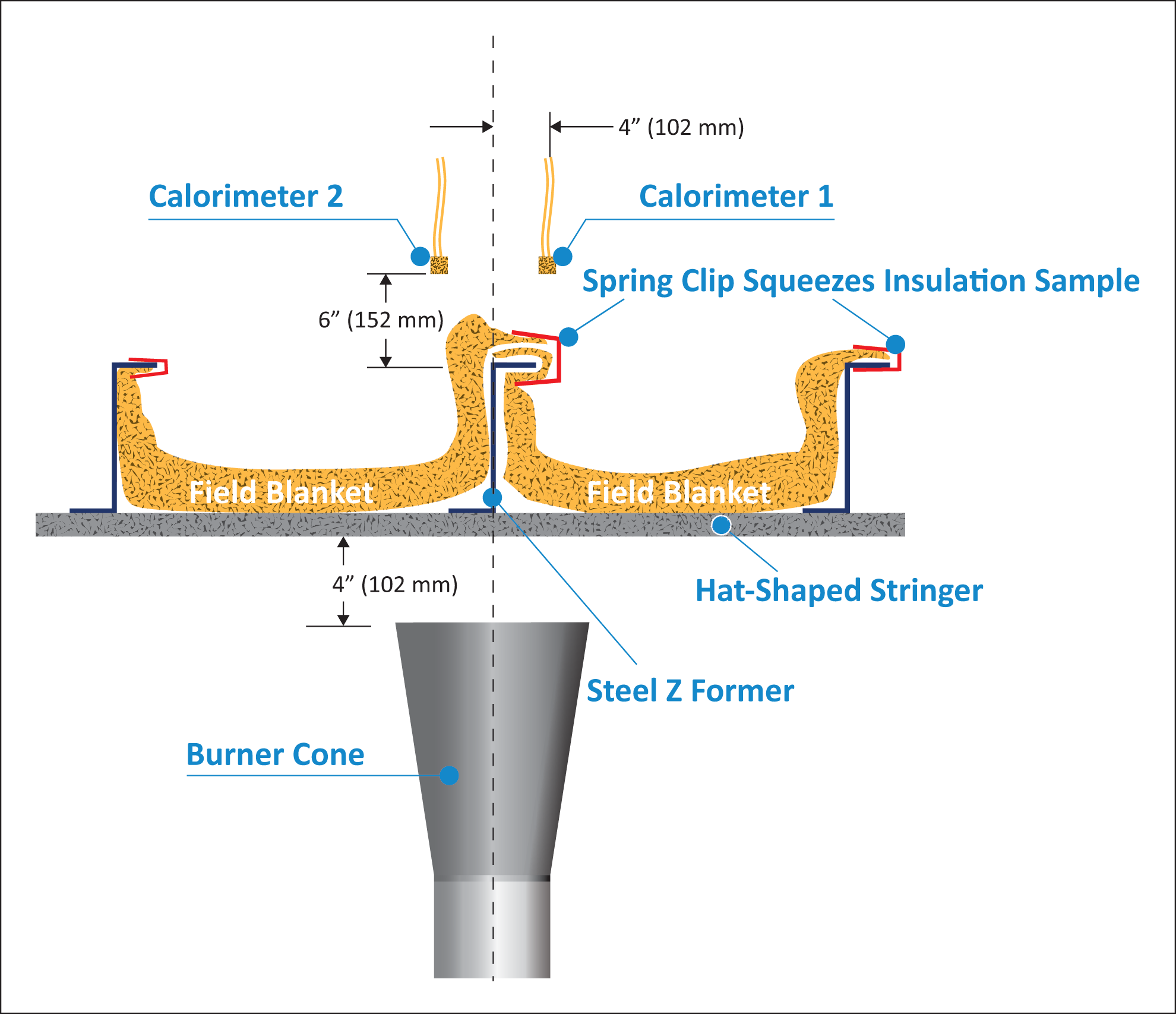
Figure 7 –
Test Specimen Installation on Test Frame
(Note: For blanket materials that cannot be installed in accordance with figure 7 above, the blankets must be installed in a manner approved by the Agency.)
(v) Conditioning. Condition the specimens at 21° ± 2°C (70° ± 5°F) and 55% ± 10% relative humidity for a minimum of 24 hours prior to testing.
(d) Preparation of apparatus.
(1) Level and centre the frame assembly to ensure alignment of the calorimeter and/or thermocouple rake with the burner cone.
(2) Turn on the ventilation hood for the test chamber. Do not turn on the burner blower. Measure the airflow of the test chamber using a vane anemometer or equivalent measuring device. The vertical air velocity just behind the top of the upper insulation blanket test specimen must be 100 ± 50 ft/min (0.51±0.25 m/s). The horizontal air velocity at this point must be less than 50 ft/min (0.25 m/s).
(3) If a calibrated flow meter is not available, measure the fuel flow rate using a graduated cylinder of appropriate size. Turn on the burner motor/fuel pump, after insuring that the igniter system is turned off. Collect the fuel via a plastic or rubber tube into the graduated cylinder for a 2-minute period. Determine the flow rate in gallons per hour. The fuel flow rate must be 0.378 ± 0.0126 l/min (6.0 ± 0.2 gallons per hour).
(e) Calibration.
(1) Position the burner in front of the calorimeter so that it is centred and the vertical plane of the burner cone exit is 4 ± 0.125 inches (102 ± 3 mm) from the calorimeter face. Ensure that the horizontal centreline of the burner cone is offset 1 inch below the horizontal centreline of the calorimeter (figure 8). Without disturbing the calorimeter position, rotate the burner in front of the thermocouple rake, such that the middle thermocouple (number 4 of 7) is centred on the burner cone.
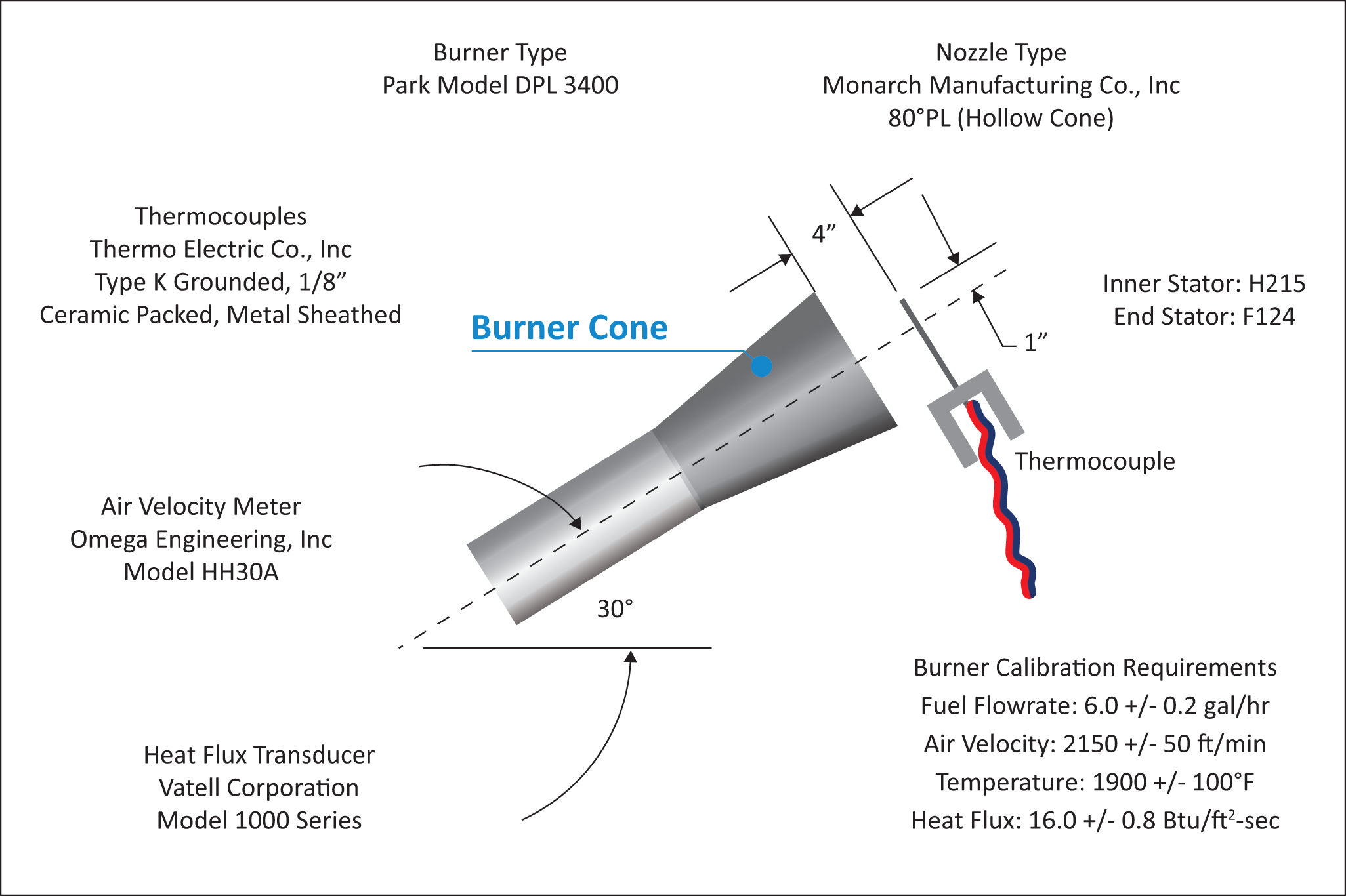
Figure 8 –
Burner Information and Calibration Settings
Ensure that the horizontal centreline of the burner cone is also offset 25.4 mm (1 inch) below the horizontal centreline of the thermocouple tips. Re-check measurements by rotating the burner to each position to ensure proper alignment between the cone and the calorimeter and thermocouple rake. (Note: The test burner mounting system must incorporate ‘‘detents’’ that ensure proper centring of the burner cone with respect to both the calorimeter and the thermocouple rakes, so that rapid positioning of the burner can be achieved during the calibration procedure.)
(2) Position the air velocity meter in the adapter or airbox, making certain that no gaps exist where air could leak around the air velocity measuring device. Turn on the blower/motor while ensuring that the fuel solenoid and igniters are off. Adjust the air intake velocity to a level of 10.92 m/s, (2150 ft/min) then turn off the blower/motor. (Note: The Omega HH30 air velocity meter measures 66.7 mm (2.625 inches) in diameter. To calculate the intake airflow, multiply the cross-sectional area 0.0035 m2 (0.03758 ft2) by the air velocity 10.92 m/s (2150 ft/min) to obtain 2.29 m3/min (80.80 ft3/min). An air velocity meter other than the HH30 unit can be used, provided the calculated airflow of 2.29 m3/min (80.80 ft3/min) is equivalent.)
(3) Rotate the burner from the test position to the warm-up position. Prior to lighting the burner, ensure that the calorimeter face is clean of soot deposits, and there is water running through the calorimeter. Examine and clean the burner cone of any evidence of build-up of products of combustion, soot, etc. Soot build-up inside the burner cone may affect the flame characteristics and cause calibration difficulties. Since the burner cone may distort with time, dimensions should be checked periodically.
(4) While the burner is still rotated to the warm-up position, turn on the blower/motor, igniters and fuel flow, and light the burner. Allow it to warm up for a period of 2 minutes. Move the burner into the calibration position and allow 1 minute for calorimeter stabilization, then record the heat flux once every second for a period of 30 seconds. Turn off burner, rotate out of position, and allow to cool. Calculate the average heat flux over this 30-second duration. The average heat flux should be 18.2 ± 0.9 W/cm2 (16.0 ± 0.8 Btu/ft2 sec).
(5) Position the burner in front of the thermocouple rake. After checking for proper alignment, rotate the burner to the warm-up position, turn on the blower/motor, igniters and fuel flow, and light the burner. Allow it to warm up for a period of 2 minutes. Move the burner into the calibration position and allow 1 minute for thermocouple stabilization, then record the temperature of each of the 7 thermocouples once every second for a period of 30 seconds. Turn off burner, rotate out of position, and allow to cool. Calculate the average temperature of each thermocouple over this 30-second period and record. The average temperature of each of the 7 thermocouples should be 1038 ± 56°C (1900 ± 100°F).
(6) If either the heat flux or the temperatures are not within the specified range, adjust the burner intake air velocity and repeat the procedures of paragraphs (4) and (5) above to obtain the proper values. Ensure that the inlet air velocity is within the range of 10.92 ± 0.25 m/s (2150 ft/min ± 50 ft/min).
(7) Calibrate prior to each test until consistency has been demonstrated. After consistency has been confirmed, several tests may be conducted with calibration conducted before and after a series of tests.
(f) Test procedure.
(1) Secure the two insulation blanket test specimens to the test frame. The insulation blankets should be attached to the test rig centre vertical former using four spring clamps positioned as shown in figure 7 (according to the criteria of paragraph (c)(3)(iv) of Part VII of this Appendix).
(2) Ensure that the vertical plane of the burner cone is at a distance of 102 ± 3 mm (4 ± 0.125 inch) from the outer surface of the horizontal stringers of the test specimen frame, and that the burner and test frame are both situated at a 30° angle with respect to vertical.
(3) When ready to begin the test, direct the burner away from the test position to the warm-up position so that the flame will not impinge on the specimens prematurely. Turn on and light the burner and allow it to stabilize for 2 minutes.
(4) To begin the test, rotate the burner into the test position and simultaneously start the timing device.
(5) Expose the test specimens to the burner flame for 4 minutes and then turn off the burner. Immediately rotate the burner out of the test position.
(6) Determine (where applicable) the burnthrough time, or the point at which the heat flux exceeds 2.27 W/cm2 (2.0 Btu/ft2 sec).
(g) Report.
(1) Identify and describe the specimen being tested.
(2) Report the number of insulation blanket specimens tested.
(3) Report the burnthrough time (if any), and the maximum heat flux on the back face of the insulation blanket test specimen, and the time at which the maximum occurred.
(h) Requirements.
(1) Each of the two insulation blanket test specimens must not allow fire or flame penetration in less than 4 minutes.
(2) Each of the two insulation blanket test specimens must not allow more than 2.27 W/cm2 (2.0 Btu/ft2 sec) on the cold side of the insulation specimens at a point 30.5 cm (12 inches) from the face of the test rig.
[Amdt 25/6]