AMC E 1030 Time limited
dispatch
ED Decision 2007/015/R
(1) Guidance
This AMC
provides guidance for obtaining type design approval of engines with EECS in a
degraded condition with respect to redundancy when these systems are to be
dispatched with Faults present for limited time intervals before maintenance
actions are required. This is commonly referred to as time limited dispatch
(TLD).
The
objective of TLD is to allow dispatch with certain EECS Faults present but
without them compromising the prescribed fleet-wide average LOTC/LOPC rates
and Hazardous Engine Effects rates.
TLD
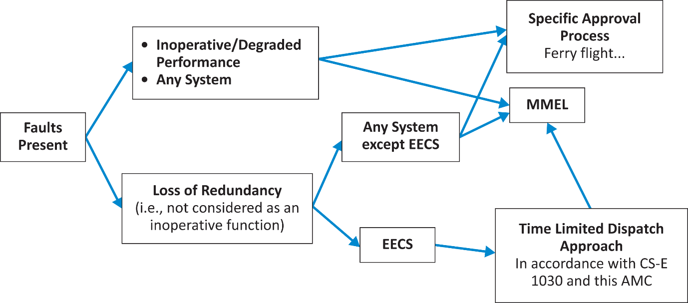
methodology is one way of managing dispatch with EECS Faults. Faults in
systems or equipment other than EECS or EECS Faults other than loss of
redundancy are typically addressed through the Master Minimum Equipment List
(MMEL). Figure 2 illustrates the various ways of managing dispatch with engine
faults.
TLD
operations have been applied to EECS equipped engines used in multi-engine
Aircraft applications, particularly those engines used in large transport
Aeroplanes (certified under CS-25). The TLD requirements and limitations for
those multi-engine Aircraft discussed in this advisory material should be
acceptable in single engine Aircraft applications. However, the criteria used
to establish acceptable TLD operations may need to be reviewed for those other
applications. This assessment of control system reliability and availability
requirements for single engine Aircraft applies to both piston and turbine
engines.
(2) Definitions
Definitions
may be found in CS-Definitions, CS-E 15 and AMC 20-3. For the purpose of this AMC E
1030 the following additional definitions apply:
“Average fault exposure time” means the average period of time between the
Fault occurring and that Fault being repaired. It applies when the periodic
inspection/repair maintenance approach is used. In this case the time of
occurrence of the Fault may not be known. One-half of the periodic inspection
interval will be used in the TLD analysis since the Fault could have occurred
at any time during the interval. This assumes that the Fault rate of
occurrence is constant throughout the interval. If the Fault rate is not
constant throughout the interval, the average exposure time should be adjusted
accordingly.
“Dispatch interval” means the maximum time interval approved for dispatch with Faults
present in the system before corrective maintenance is required.
“MEL maintenance approach” means that the presence of a detected TLD approved fault in the EECS
will be annunciated in the cockpit and that in the presence of the fault
indication dispatch will be allowed by including the indication in the MMEL.
The operator can then keep the indication listed within their approved MEL and
disposition the indication as they do any other MEL items.
“Inspection/Repair maintenance approach” means that a periodic inspection and repair strategy has been approved to
manage FADEC system faults. Within this approach, the presence of a
detected TLD approved fault in the EECS need not be annunciated to the flight
crew. The FADEC system must be
interrogated by maintenance for the presence of faults during periodic
inspections, and the faults found must be repaired within a specified time
period or interval, so that the average exposure time of a fault in a particular
category does not exceed the maximum average allowed exposure time for that
category.
(3) Referenced Documents
ARP 5107
revB, Time-Limited-Dispatch (TLD) Analysis for Electronic Engine Control
Systems, dated November 2006.
SAE World
Headquarters, 400 Commonwealth Drive, Warrendale, PA 15096-0001, USA.
(4) Time Limited Dispatch Analysis
The factors and limitations used throughout this AMC, and in Tables 2 and
3 in particular, are examples and are used for illustrative purposes
only. However, where supporting data
and analysis are not available, the values quoted may be used as default
values.
The TLD
analysis should establish the dispatchable configurations. The TLD report
should define the dispatchable configurations in terms of the Faults and their
associated dispatch intervals. The TLD analysis, typically a Markov analysis
or Fault tree analysis, should show that the fleet-wide average reliability or
“average LOTC/LOPC rate,” which includes full-up as well as degraded system
dispatches (including those resulting from Uncovered Faults), meets the
required LOTC/LOPC rate for the assumed installation (see also AMC 20-3).
The TLD
analysis that substantiates compliance with the required LOTC/LOPC rate should
be summarised in a graph. An example of such a graph is shown in Figure 1. The
ordinates of the graph should be the estimate of fleet-wide average LOTC/LOPC
rate of the EECS versus the dispatch interval(s) (in hours) for the EECS
Faults.
If
dispatchable EECS Faults have been grouped into two categories, a short-time
dispatch (or repair) category and a long time dispatch (or repair) category
(see paragraph (6) below), the ordinate of the graph should show a long time
dispatch interval of at least twice the length of time of the dispatch
interval being requested. When calculating the LOTC/LOPC rate as a function of
the long time dispatch interval, the assumed short-time dispatch interval
should be twice the requested short-time dispatch interval. This factor of two
is used to cover uncertainties in the analysis itself.
In the TLD
analysis, all Uncovered Faults should be assumed to lead to LOTC/LOPC unless
it can be shown that they do not directly result in an LOTC/LOPC. The TLD
analysis should provide the rationale and substantiation for the Failure rates
used for Uncovered Faults.
(5) Certification specifications for all
dispatchable configurations.
(a) CS-E 1030(b) and (c) prescribes the requirements for
all dispatchable configurations.
(b) CS-E 1030(b)(3) is directed at protection systems
within the EECS that provide the sole means of mitigation from Hazardous
Engine Effects. There may be some cases that have a degree of protection from
other sources. Such cases may best be addressed through the MMEL rather than
the TLD.
(c) CS-E 1030(b)(5) stipulates that when dispatching
with single or multiple Faults, there can be no further single Failure in the
Engine Control System that would create a Hazardous Engine Effect. For
example, it is necessary to ensure that the over-speed protection system
function is operational at dispatch to guard against a Hazardous Engine Effect
resulting from a single additional Fault driving fuel flow upwards.
(d) CS-E 1030(b)(6) requires that the applicant shows
that the Engine, in all dispatchable configurations, continues to operate
satisfactorily in the external threat levels for the system and remain
compliant with the corresponding certification specifications. The Engine in
each permitted TLD configuration should maintain the capability of operating
through the external threats considered during Engine certification e.g.
icing, rain, hail, birds, EMI, HIRF and lightning.
Relative to
HIRF and lightning, compliance is typically, but not always, addressed by
conducting the tests in the worst-case dispatchable configuration. This worst
case is often represented by single channel operation. The other external
threats are typically addressed by analysis.
(e) In showing compliance with CS-E 1030(b)(7), justification of the proposed dispatch intervals should be based on a
reliability analysis. The reliability analysis is typically the result of a
model of the EECS, like a Markov Model or a Fault Tree Analysis, and is based
largely on electronic component databases for failure rates.
A Summary
Report of the Engine Control System time-limited-dispatch analysis should be
prepared and made available to the installer. This report should contain the
list of the non-dispatchable and time limited dispatch configurations.
A means to
monitor the in-service LOTC/LOPC rate should be established. This should
compare service experience of component Failures with the modes, effects,
rates, and exposure times predicted in the TLD analysis. The data collected by
this means may be used to support applications for changing dispatch intervals
and may be incorporated into the system required by Part 21A.3.
Entry level
and mature level EECSs are differentiated to consider factors not included in
a reliability analysis.
A mature
level system is an EECS that has achieved a stable in-service LOTC/LOPC rate
that meets the required LOTC/LOPC rate for the intended application and is
consistent with the analysis on which TLD approval is based. For engines
installed in large transport aeroplanes this might not be achieved until
250,000 Engine flight hours in-service operation have been accumulated.
An EECS is
classified as an entry-level system if it is not a mature level system.
The
applicant may request alleviation from entry level classification if it has
sufficiently similar systems operating in the field that have accumulated
enough flight hours to establish stable behaviour over time. Such applications
will be reviewed on a case-by-case basis.
A
reliability analysis is typically based on electronic component databases.
These databases consider components to be mature and, hence, only random
Failures are considered. Failures due to design, manufacturing, quality and
operating environment of the EECS, as well as maintenance errors, are not
included.
Since such
failures due to design, manufacturing, quality and operating environment of
the EECS, as well as maintenance errors,
are not covered by the reliability analysis, and because these Faults
tend to be exposed and corrected only as in-service time is accumulated, the
EECS is classified as an entry-level system and appropriate limitations are
applied as shown in Table 2. Thus, more conservative criteria for dispatch
intervals for entry-level systems are applied compared to mature level
systems, even though the reliability analysis may support dispatch for a
longer dispatch interval for entry-level systems.
The TLD
analysis report should include a tabulation of the various proposed dispatch
configurations and provide: (1) the expected frequency of occurrence of the
Faults leading to those dispatchable configurations; and (2) the LOTC/LOPC
rate of the system when operating in those configurations.
The report
should tabulate the chosen category described in paragraph (6) for each Fault
covered in the analysis. The report should also show that the exposure time
chosen for the short and long time Fault categories allows the EECS to
continue to meet its reliability requirements.
(6) Dispatch Categories
The dispatch
intervals determined in compliance with CS-E 1030(b)(7) and (c) are usually grouped into dispatch categories.
The
following are typical dispatch categories:
(a) No Dispatch. Configurations that do not
comply with CS-E 1030(b) and/or (c) or do not qualify for another
category should be categorised as No Dispatch.
(b) Short Time Dispatch. Configurations that
comply with CS-E 1030(b) and/or (c) and satisfy the following
condition should be categorised as Short Time Dispatch: the computed LOTC/LOPC
rate with the Fault(s) present is less than or equal to an upper limit that
has been set at 10 times the fleet-wide average reliability criteria or “average
LOTC/LOPC rate” for the installation. (The LOTC/LOPC rates for different
installations may be found in AMC 20-3.)
However,
even if the Long Time Dispatch LOTC/LOPC rate is met, configurations where the
EECS has reverted to essentially single channel operation or has lost a
significant degree of redundancy should be categorised as Short Time.
(c) Long Time Dispatch. Configurations that
comply with CS-E 1030(b) and/or (c) and satisfy the following
condition should be categorised as Long Time Dispatch: the computed LOTC/LOPC
rate with the Fault(s) present is less than or equal to 75 percent of an upper
limit that has been set at 10 times the fleet-wide average reliability
criteria or “average LOTC/LOPC rate” for the installation. (The LOTC/LOPC
rates for different installations may be found in AMC 20-3.)
(d) Applicant defined dispatch. This category
is for Faults that do not have an impact on the LOTC/LOPC rate. These Faults
do not have to be included in the LOTC/LOPC analysis. It should be
substantiated that these Fault conditions do not have an impact on the
LOTC/LOPC rate. These configurations should be included in the TLD summary
report to enable an appropriate maintenance programme to be developed.
(7) TLD Operations Associated with the “MEL
Maintenance Approach” and with the “Inspection/Repair Maintenance Approach.”
The dispatch
intervals for Short Time and Long Time dispatch will also depend upon the
approach used in the maintenance programme. Where a “MEL Maintenance Approach”
is used, and hence the time of initial occurrence of the Fault is known, the
dispatch interval starts from the point in time when the MEL procedures
identify the presence of the fault. In
the “Inspection/Repair maintenance approach”, the Fault is assumed to have
occurred half-way through the inspection interval and the dispatch interval is
therefore assumed to have started accordingly from this mid-point. In each
case, the analysis should support the dispatch interval(s). Table 3 shows an
example of operating times for TLD Operations Associated with the “MEL
Maintenance Approach” and with the “Inspection/Repair Maintenance Approach.”
(8) Declaration of approved TLD operating
limitations
The approved
TLD operating limitations should be declared in the manuals specified in CS-E 20(d)
and CS-E 25(a), whichever is appropriate, and provided to
operators as required by Part 21A.61. The approved TLD operating limitations
are the times allowed for rectification of Faults. An example of the typical
operating limitations for TLD is provided in Table 1. The fact that the Engine
has been approved for TLD operations should be recorded in the Engine TCDS
(See CS-E 40(d)).
(9) Flight Crew Indication
CS-E 1030(e) requires provisions for indication to the flight crew for no-dispatch configurations. This does not mean that indication during flight is required. Indication on the ground only is an acceptable means of compliance.
Table 1.
Typical Operating Limitations for TLD
|
This page gives the EASA-approved time limits to
operate this engine (identify engine manufacturer and model) with control
system Faults present. These limits are also defined in engine report
(identify report number and date), the Engine Control System Time-Limited-Dispatch
Summary Report. |
|
|
Fault Category |
Operational Limitation |
|
NO DISPATCH |
DISPATCH NOT ALLOWED WITH THIS CONDITION PRESENT. Note 1: There must be a flight deck display of the
presence of a no dispatch condition |
|
SHORT TIME |
DISPATCH IS ALLOWED WITH SHORT TIME FAULTS PRESENT.
THE MAXIMUM (AVERAGE – IF APPLICABLE) EXPOSURE TIME OF THE SYSTEM TO THESE
FAULTS MUST BE LIMITED TO (insert XXX) FLIGHT HOURS. Note 2: All Faults in this short time category must
be corrected within a time period, such that (a) each Fault in the group
does not have an exposure time greater than (insert XXX) hours, OR (b) the
average exposure time for short time Faults does not exceed (insert XXX)
hours. Also, it is noted that the time limitations contained herein with
respect to short time EECS Faults may only be changed with approval of the
agency. —
If an MEL Maintenance Approach is used for this Fault category,
there should be an appropriate generic flight deck display of the presence
of a short time Fault condition(s). —
If a Periodic Inspection/Repair Maintenance Approach is used,
the system should be inspected for short time Faults at an interval, such
that if Faults are found, they can be repaired so that the average length of
time that a Fault is present in the system (average fault exposure time)
does not exceed the specified (insert XXX) hour limitation. Reference SAE ARP5107 revB for a more complete
understanding of these maintenance approaches. |
|
LONG TIME |
DISPATCH IS ALLOWED WITH LONG TIME FAULTS PRESENT.
THE MAXIMUM (AVERAGE – IF APPLICABLE) EXPOSURE TIME OF THE SYSTEM TO THESE
FAULTS MUST BE LIMITED TO (insert YYY) FLIGHT HOURS. Note 3: All Faults in this long time category must
be corrected within a time period, such that (a) each Fault in the group
does not have an exposure time greater than (insert YYY) hours, OR (b) the
average exposure time for long time Faults does not exceed (insert YYY)
hours. Also, it is noted that the time limitations contained herein with
respect to long time Electronic Engine Control System Faults may only be
changed with approval of the agency. —
If an MEL Maintenance Approach is used for this Fault category,
there should be an appropriate generic flight deck display of the presence
of a long time Fault condition(s). —
If a
Periodic Inspection/Repair Maintenance Approach is used, the system should
be inspected for long time Faults at an interval, such that if Faults are
found, they can be repaired so that the average length of time that a Fault
is present in the system (i.e., average fault exposure time) does not exceed
the specified (insert YYY) hour limitation. |
Table
2. An Example of Operating Times for TLD Operations associated with the MEL
maintenance approach.
Limitations on Electronic Engine Control
System Operations with Faults Present
|
Experience
Level |
No Dispatch
Category |
Short Time
Faults Category - maximum operating time |
Long Time
Faults Category – maximum operating time |
Electronic
Engine Control System Faults Not Affecting the LOTC/LOPC Rate |
|
Entry Level |
No Flight Allowed |
125 Engine flight hours. |
250 Engine flight hours. |
(2) |
|
Mature Level |
No Flight Allowed |
(1) |
(1) |
(2) |
Notes:
(1) Times vary depending upon the results of
the TLD Analysis.
(2) The time to repair should be included in
an appropriate document.
Table
3. Maximum Operating Times for TLD Operations Associated with the “MEL
maintenance approach” and “Inspection/Repair maintenance approach.”
Limitations on Electronic Engine Control
System Short Time and Long Time Operations with Faults Present
|
|
Short Time Faults |
Long Time Faults |
||
|
Experience
Level |
Time of Fault occurrence known and MEL maintenance approach used – max operating time with Fault(s) present |
Time of Fault occurrence unknown and Periodic Inspection/ – |
Time of Fault occurrence known and MEL maintenance approach used – max operating time with Fault(s) present |
Time of Fault occurrence unknown and Periodic Inspection/ – max periodic inspection/repair interval |
|
Entry
Level |
125 engine
flight hours. |
250 engine
flight hours. |
250 engine
flight hours. |
500 engine
flight hours. |
|
Mature
Level |
(1) |
(2) |
(1) |
(2) |
Notes:
(1) Times vary depending upon the results of
the TLD Analysis.
(2) Should be equal to two times the value of note (1)
Figure
1. Example of the analysis results for a system with both Short Time Dispatch
and Long Time Dispatch
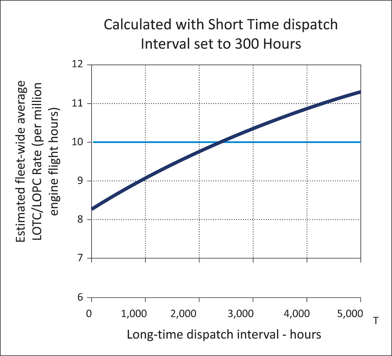
In this
example,
—
The
analysis was conducted with the Short Time dispatch interval set to 300 hours
based on the assumption that the desired Short Time approval was 150 hours.
This ratio is in accordance with paragraph (4)
—
The
target average LOTC / LOPC rate is 10 per million engine flight hours
—
The
analysis shows that the target rate is not exceeded with a declared Short Time
dispatch interval set to 150 (= 300/2) hours and the Long Time less than 2700
hours. However, the long-time interval would be limited to an operational time
of 1,350 hours. Again this ratio is in accordance with paragraph (4).
—
In
the case of an entry level system the short-time Fault category would be
limited to an operational time period of 125 hours, and Faults in the
long-time interval would be limited to an operational time of 250 hours. This
is in accordance with Table 2.
—
If
the long-time Faults were to be addressed using the periodic inspection/repair
maintenance approach, the inspection/repair interval could not be longer than
500 hours for entry level system and 2,700 hours for a mature level system.
This in accordance with Table 3.
—
If
the short-time Faults were to be addressed using the periodic
inspection/repair maintenance approach, the inspection/repair interval could
not be longer than 250 hours for entry level system and 300 hours for a mature
level system. This in accordance with Table 3.
[Amdt No: E/1]