AMC E 800 Bird Strike and Ingestion
ED Decision 2018/014/R
(1) Ingestion tests
(a) Single large bird
(i) The applicant is required to provide an analysis substantiating the definition of the 'most critical exposed location' (CS-E 800(b)(1)(iii)). Determination of this location should include evidence where necessary on:
— the effect of the bird strike on rotating components (excluding any spinner);
— the compressor casing strength;
— the possibility of multiple blade Failures;
— the strength of the Engine structure and main shafts relative to the unbalance and the excess torque that are likely to occur.
(ii) To comply with CS-E 800(b)(1)(ii)(A), rig tests may be used to determine whether a bird of a particular size will pass through the inlet.
(iii) The complete loss of power or thrust is acceptable after the ingestion of the single large bird.
(b) Large flocking bird
The following advisory material applies to the test required by CS-E 800(c):
(i) The minimum first stage rotor rotational speed (N1) at which the Engine should be stabilised before ingestion should be determined from the Engine performance data. The term 'Rated Take Off Thrust' means the maximum take-off thrust produced at sea-level static conditions on an ISA standard day.
(ii) The applicant should select a target on the first exposed rotating stage(s) of the Engine (e.g. the fan) at a blade span height of 50%, or further outboard, as required by CS-E 800(c)(1)(iv) (see the figure below). The specified target location is at the discretion of the applicant.
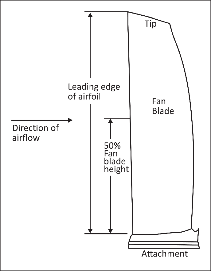
The use of ‘stage(s)’ is intended to allow for alternative designs such as rear-mounted fans for which each exposed stage will be evaluated independently.
(iii) When setting the thrust between the steps of the 20-minutes run-on period, momentary thrust drops below the specified values may be acceptable as long as the duration does not exceed 3 seconds.
(iv) The Engine is required to continue to run for 20 minutes and produce no less than 50% of the Rated Take-off Thrust for the initial 14 minutes. During the first minute, the thrust lever is not to be manipulated. During step 2, the thrust lever may be manipulated at the discretion of the applicant to seek a power setting where the engine can continue to operate, for example to minimise exceedances and/or vibration, provided that at least 50% of the Rated Take-off Thrust is maintained. However, a momentary thrust drop below this value may be acceptable as long as the duration does not exceed 3 seconds.
(v) Following the initial 14 minutes, the thrust is reduced, and a maximum of 30 seconds is allowed for the applicant to manipulate the thrust lever to find the specified thrust. This is to allow for potential damage to the Engine, which might require careful throttle management.
(vi) The components referred to in CS-E 800(g)(3)(ii)(A) include, for example, fan blades and their retention / spacer components, fan outlet guide vanes, spinners, fan disks and shafts, fan cases, frames, main bearings and bearing supports, including frangible bearing assemblies or devices. The intent is that a subassembly test should adequately represent the mechanical aspects of a type design Engine during the large flocking bird ingestion.
(vii) The dynamic effects (and related operability concerns) referred to in CS-E 800(g)(3)(ii)(C) include, but are not limited to, surge and stall, flameout, limit exceedances, and any other considerations relative to the ability of the type-design Engine to comply with the specifications of CS-E 800(c).
(c) Medium and small flocking birds
(i) The Engine test of CS-E 800(d) will demonstrate that the Engine will produce the required power or thrust, while maintaining acceptable handling characteristics during a 20-minute run-on simulating a return to the airport after the ingestion of medium or small flocking birds at take-off. This will consequently demonstrate compliance with CS-E 540(b).
(ii) The applicant will identify under CS-E 800(d)(1)(ii) all the critical locations and those which have to be used during the small or medium bird engine ingestion tests, and appropriately consider the potential effects of the assumed aircraft installations. The spinner and the other parts of the front of the Engine may be evaluated separately under CS-E 800(f).
(iii) In the tests performed under paragraph CS-E 800(d), the Engine is required to produce at least 75% of the test conditions power or thrust after the ingestion of either small or medium birds. Nevertheless, a momentary power/ thrust drop below this value is acceptable, but its duration should not exceed 3 seconds after the ingestion.
(iv) Exceedances of Engine operating limitations associated with Take-off conditions should not occur during the first 2 minutes following the ingestion of the birds in the 20-minute run-on test. If an exceedance of limits occurs during these 2 minutes, except during the first 3 seconds of the test, this should be considered when complying with CS-E 700. After these initial 2 minutes without any power lever movement, it is permitted to control exceedances, if any. Any intervention to control exceedances should be recorded, and suitable instructions should be provided in the instructions for the installation of the Engine. After any such power lever adjustment, the Engine should still produce the required power or thrust for the test. In CS-E 800(d)(1)(iii) and (iv), a movement of the power lever means an action on the means which provides a power or thrust setting for the Engine control. This can be a mechanical device in the test facility control room or an electronic signal sent to the Engine Control System.
(d) Core
Engine flocking bird ingestion test
(i) Determining
climb rotor speeds
The
calculation of the core ingestion test Engine rotor speeds associated with the
climb phase will depend on the aeroplane and the type of flight that is flown.
For each Engine model and installation (where known), the Engine manufacturer
should:
—
determine the Engine rotor speeds that provide the
thrust that is required, at an altitude of 3 000 ft (above
ground level) to climb
—
through that altitude, in International Standard
Atmosphere (ISA) standard day conditions at 250 knots indicated airspeed
(IAS);
—
include the rotor speeds that were assumed in the
instructions for installation as required by CS-E 20(d);
—
establish the associated minimum mechanical fan
rotor speed for this condition using Engine performance simulations;
—
the fan speed chosen should be associated with the
lowest rated thrust Engine model offered for that aircraft installation; if
multiple climb settings are available for an intended aircraft, then the
lowest climb setting should be used to determine the core ingestion rotor
speed targets.
(ii) Climb
rotor speed considerations
There is typically little or no difference between the take-off and
climb rotor speeds for the smaller turbofan Engines that are installed on
business jets. For this reason, the climb conditions for the core ingestion
demonstration will often be very close to the conditions prescribed for the
medium flocking bird (MFB) test of CS-E 800(d), in which the largest MFB is
targeted at the core at the full-rated take-off condition.
The most significant difference between the MFB test and the core
ingestion demonstration is expected to be the bird speed determined in CS-E
800(f) versus the 250-knot IAS core Engine test bird speed. An applicant who
wants to demonstrate the recommended 250-knot IAS core bird within the
existing MFB rated take-off test may do so if the applicant can show an
equivalent level of test severity. Therefore, it is possible for the MFB core
ingestion requirements to be satisfied by a single test at the rated Take-off
Thrust in which the largest MFB that is aimed at the core is fired into the
engine at the 250-knot IAS climb airspeed while the remaining bird velocities,
targeting and run-on would follow the current MFB criteria. All the birds in
the test would still have to be fired within the 1-second requirement of CS-E
800(d)(1)(iii). The objective is to show that the core ingestion is as
rigorous at the current MFB fan speed condition as it would be at the
aeroplane recommended climb fan speed condition.
(iii) Target
selection and timing
—
The bird should be targeted at the Engine in order
to maximise the amount of bird material that enters the core for the given
test condition. This will ensure that the core ingestion test properly
challenges the core during an Engine demonstration.
—
The optimum target location varies with the Engine
design. The span-wise location will depend on the geometric features of the
front of the Engine.
—
The core bird target location should be determined
so that it maximises the amount of core ingested bird material for the core
ingestion test by:
—
analysis based on component testing;
—
dynamic simulation verified by test; or
—
experience with similar designs.
(iv) Engine
operation
—
A momentary, 3 seconds maximum, power or thrust
decrease below the required value of each segment, or when setting power
between segments, is acceptable.
—
A power or thrust loss of greater than 3 seconds
duration below the required value of each segment, or when setting power
between segments, is considered to be a sustained power loss.
(v) Run-on
sequence requirements
—
The total test duration may exceed 20 minutes, due
to the time used for accelerations and decelerations.
—
If a percentage of the maximum rated Take-off
Power or Thrust is specified, the rotor speed to attain the specified Power
setting will vary with the test day conditions.
—
The Power settings are a percentage of the maximum
rated Take-off Power or Thrust, and not a percentage of the actual test day
pre-ingestion Power or Thrust specified in CS-E 800(e)(1) or (4).
(vi) Core
ingestion prediction analyses
—
Some Engine configurations may include features
that reject all bird material from the core intake at the take-off and climb
conditions specified in CS-E 800(d) and (e)(1). Such Engines would be:
—
exempt from the recommended climb ingestion
criteria;
—
subject only to the approach core ingestion test;
and
—
required to demonstrate 100 % bird rejection
capability by analysis or similarity.
—
Any analyses used to predict core ingestion will
need to be validated using data that may be derived from:
—
rig testing;
—
Engine testing; or
—
field experience.
—
If the standard CS-E 800(d) MFB core demonstration
results in any amount of bird material being found in the core, including a
single feather or tissue fluorescence under ultraviolet light illumination,
then:
—
the prediction of zero core ingestion under the
climb conditions of CS-E 800(e)(1) will be considered to be invalid; and
—
the core ingestion capability in the climb
condition should be demonstrated.
(2) Test facility related conditions
(a) The test facility should be appropriately calibrated to ensure that those controlling parameters defined by the analysis of the critical conditions which cannot be accurately controlled (e.g. the bird speed, aiming locations) are within an acceptable tolerance. This tolerance band should be derived from an analysis of the sensitivity of the critical impact parameter (CIP) to variations in the controlling parameters.
The 'critical impact parameter (CIP)' is defined as a parameter that is used to characterise the state of stress, strain, deflection, twist, or other condition which will result in the maximum impact damage to the Engine for the prescribed bird ingestion condition.
The CIP is generally a function of such things as the bird mass, bird velocity, fan/rotor speed, impact location, and fan/rotor blade geometry. The state of maximum impact damage to the Engine is relative to the ability to meet the criteria of CS-E 800. The CIP for most modern turbofan Engines is the fan blade leading edge stress, although other features or parameters may be more critical as a function of the operating conditions or the basic design. For turboprop and turbojet Engines, a core feature will most likely be the critical consideration. Regardless of the Engine design, the most limiting parameter should be identified and understood prior to any demonstration, as any unplanned variations in controlling test parameters will be evaluated for their effect on the CIP and CS-E 800 specifications.
For turbofan first stage fan blades, increasing the bird velocity or bird mass will increase the slice mass, and could shift the CIP from the leading edge stress to the blade root stress. For fan blades with part span shrouds, it may be the blade deflection that produces shroud shingling and either a thrust loss or a blade fracture that could be the limiting event. For unshrouded wide chord fan blades it may be the twist of the blade in the dovetail that allows it to impact the trailing blade, resulting in trailing blade damage.
For certification tests, the CIP variation should not be greater than 10% as a function of any deviation in the controlling parameters of the test.
(b) The installation and especially the gun arrangement in some test facilities can induce air distortion in the Engine inlet, which can artificially reduce the stability margins of the Engine. This should be identified prior to the test.
(c) Power or thrust should be measured by a means which can be shown to be accurate throughout the test to enable the power or thrust to be set without undue delay and maintained to within ± 3 percentage points of the specified levels. For the test of CS-E 800(d), if, after the first 2 minutes, operation at the specified power or thrust levels would result in a sustained high vibratory condition, the power or thrust may be varied within the ± 3% band. Alternative load devices of some test facilities may be unable to control the power level tolerance band to the desired level. This should be identified and approved prior to the test. Any exceedance of this ± 3% band should be justified in relation to the objectives of CS-E 540(b) or CS-E 800(d).
(d) If turboprop or turboshaft Engines are tested using an alternative load device which could induce different Engine response characteristics than when the Engine is coupled with a propeller or installed in the aircraft, the interface with the test facility and aircraft or propeller systems should be monitored during the test and should be used to determine how the Engine would respond in a representative installation, and to ensure that the Engine would then comply with the specifications.
(e) Input and output data across the Engine interfaces with the aircraft systems should be provided by the Engine manufacturer in the instructions for installation regarding the expected interaction of the Engine with these systems during ingestion events. Of particular interest would be dynamic interactions such as auto surge recovery, any propeller autofeather.
(3) Impact
(a) The front of the Engine is defined as any part of the Engine which can be struck by a bird. This includes but is not limited to components such as a nose cone/spinner on the fan or compressor rotor, an Engine inlet guide vane assembly including the centrebody, any protection device, or inletmounted components.
(b) Ingestion is defined as the passage of a bird into the rotating blades.
(c) The term 'first stage rotor blades' when used in CS-E 800 includes the first stage of any fan or compressor rotor which is susceptible to a bird strike or bird ingestion. These first stage rotor blades are considered to be part of the front of the Engine. This definition encompasses ducted, unducted and aft fan designs. For aft fan designs, blades on two different rotors (in the primary and secondary flows) would probably need to be considered.
(4) General
(a) The Engine configuration for the test should comply with CS-E 140. The normal functioning of automatic systems that do not require pilot intervention is acceptable provided that the dispatch criticality is addressed in the appropriate documentation. Systems which are not part of the Engine, such as a propeller autofeather system, should be disabled. Any OEI ratings do not have to be taken into account for compliance with CS-E 800(d).
(b) The minimum Engine referred to in CS-E 800(b)(1)(i) or (d)(1)(i) is defined as a new Engine that exhibits the type design’s most limiting operating parameters with respect to the bird ingestion conditions prescribed by CS-E 800. These operating parameters include, but are not limited to the power or thrust, turbine temperature and rotor speed(s).
(c) CS-E 800(g)(1) is intended to allow the certification of design changes or derivative Engines without conducting a full Engine test. It is not intended, considering the present state of the art, to be used for the certification of new Engines. However, it offers the possibility of future advancement. Any parametric analysis used to substantiate derivative Engines as allowed under CS-E 800(g)(1) should fall within a 10% variation in the CIP that was used to substantiate the original base Engine. The CIP(s) is (are) often associated with the impact load at the point of bird and rotor blade contact. This is generally a function of bird speed, rotor speed, and blade twist angle. This 10% variation in the CIP should not be assumed to be a direct tolerance on the applicant's proposed changes to the take-off power or thrust ratings themselves.
(d) Any analytical means used in place of a test demonstration (where analysis is permitted) should be validated by evidence that is based on representative tests and should have demonstrated its capability to predict Engine test results.
(e) When reference is made to an “exposed location”, this should be understood to be any part of the Engine which is not shielded.
(f) When the CS-E 810 test is proposed as an alternative to the single large bird test (see CS-E 800(g)(2)), the demonstration should include consideration of unbalance, as well as effects of the axial loading from the bird strike on bearings or other structures.
(g) Artificial birds may be used in the tests if they are internationally standardised and are acceptable to the Agency.
[Amdt No: E/1]
[Amdt No: E/5]