AMC E 515 Engine Critical Parts
ED Decision 2018/014/R
(1) Introduction
Because the Failure of an Engine Critical Part is likely to result in a Hazardous Engine Effect, it is necessary to take precautions to avoid the occurrence of Failures of such parts. Under CS-E 510(c), they are required to meet prescribed integrity specifications.
For that purpose, an Engineering Plan, a Manufacturing Plan and a Service Management Plan are required under CS-E 515. These three plans define a closed-loop system which link the assumptions made in the Engineering Plan to how the part is manufactured and maintained in service; the latter two aspects are controlled by the Manufacturing and Service Management Plans respectively. These plans may generate limitations which are published in the Airworthiness Limitation Section of the Instruction for Continued Airworthiness. This AMC provides means for the establishment of such plans.
(2) General
(a) Identification of Engine Critical Parts
The safety analysis required under CS-E 510 identifies Engine Critical Parts that are required to comply with CS-E 515. An Engine Critical Part is a Critical Part, by definition, with regard to compliance with Part 21.
If a part is made of various sub-parts, which are finally integrated in an inseparable manner into a unique part, and any one of the sub-parts is identified as an Engine Critical Part, the entire part is then treated as an Engine Critical Part.
(b) Attributes of a part
‘Attributes’ include, but are not limited to, material mechanical properties, material microstructure, material anomalies, residual stress, surface condition, and geometric tolerances. Processes such as alloy melting practise, ingot conversion to billet or bar, forging, casting, machining, welding, coating, shot peening, finishing, assembly, inspection, storage, repair, maintenance and handling may influence the Attributes of the finished part. Environmental conditions experienced in service may also affect the Attributes.
(c) Content of a plan
The Engineering Plan, Manufacturing Plan and Service Management Plan should provide clear and unambiguous information for the management of the Engine Critical Parts.
‘Plan’, in the context of this rule, does not necessarily mean having all technical information contained in a single document. If the relevant information exists elsewhere, the plan may make reference to drawings, material specifications, process specifications, manuals, etc., as appropriate. It should be noted that these references should be clear enough to uniquely identify the referenced document. The plan should allow the history of the individual part number to be traced.
(3) Means for defining an Engineering Plan
(a) Introduction
The Engineering Plan consists of comprehensive life assessment processes and technologies that ensure that each Engine Critical Part can be withdrawn from service at a life before Hazardous Engine Effects can occur. These processes and technologies address the design, test validation, and certification aspects, and also define those manufacturing and service management processes that should be controlled in order to achieve the Engine Critical Part design intent.
(b) Elements
of the Engineering Plan
The Engineering Plan should address the following subjects:
— Analytical and empirical engineering processes applied to determine the Approved Life.
— Structured component and Engine testing conducted to confirm Engine internal operating conditions and to enhance confidence in the Approved Life.
— Establishment of the attributes to be provided and maintained for the manufacture and service management of Engine Critical Parts.
— Development and certification testing, and service experience required to validate the adequacy of the design and Approved Life. Any in-service inspections identified as critical elements to the overall part integrity, should be incorporated into the Service Management Plan.
(c) Establishment
of the Approved Life – General
Determining the life capability of an Engine Critical Part involves the consideration of many separate factors, each of which may have a significant influence on the final results.
It is possible that the final life calculated may be in excess of that considered to be likely for the associated airframe application. However, the life, in terms of cycles or hours, as appropriate, should still be recorded in the Airworthiness Limitations Section in order for the usage of the part to be properly tracked.
(d) Establishment of the Approved Life - Rotating parts
The following describes a typical process for establishing the Approved Life of rotating parts:
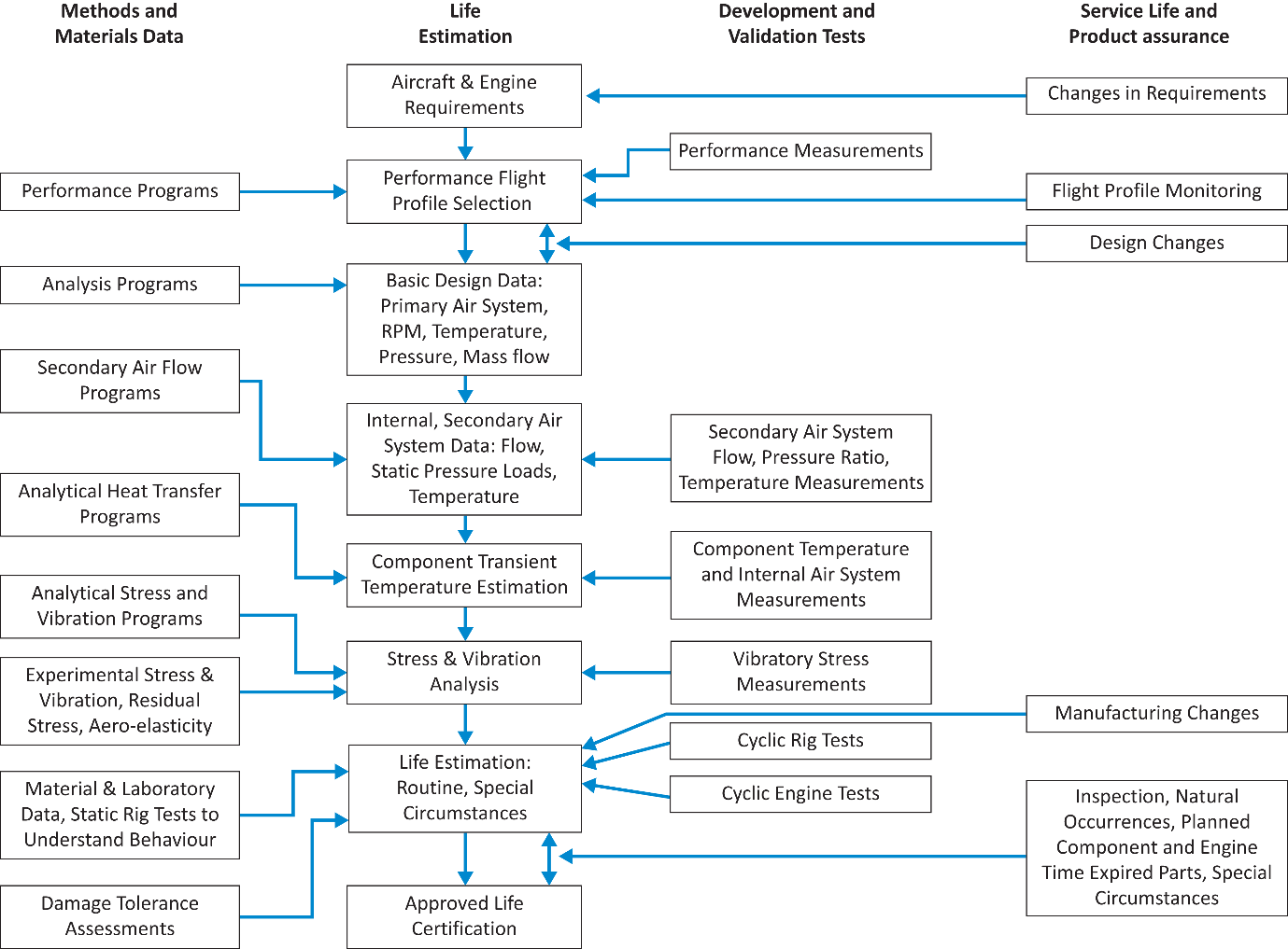
The major elements of the analysis are:
(i) Operating conditions.
For the purposes of certification, an appropriate flight profile or combination of profiles and the expected range of ambient conditions and operational variations will determine the predicted service environment. The Engine Flight Cycle should include the various flight segments such as start, idle, takeoff, climb, cruise, approach, landing, reverse and shutdown. The assumed hold times at the various flight segments should correspond to the assumed limiting installation variables (aircraft weight, climb rates, etc.). For Rotorcraft turbine Engines, the representative usage of the 30-minute Power rating should be considered in the Engine Flight Cycle when establishing the Approved Life of each Engine critical part. A maximum severity cycle that is known to be conservative may be used as an alternative.
The corresponding rotor speeds, internal pressures, and temperatures during each flight segment should be adjusted to account for Engine performance variation due to production tolerances and installation trim procedures, as well as Engine deterioration that can be expected between heavy maintenance intervals. The range of ambient temperature and take-off altitude conditions encountered during the Engines’ service life as well as the impact of cold and hot Engine starts should also be considered.
The appropriateness of the Engine Flight Cycle should be validated and maintained over the lifetime of the design. The extent of the validation is dependent upon the approach taken in the development of the Engine Flight Cycle. For example, a conservative flight cycle where all the variables are placed at the most life-damaging value would require minimum validation, whereas a flight cycle which more accurately represents some portion of the actual flight profile but is inherently less conservative, would require more extensive validation. Further refinements may be applied when significant field operation data is gathered.
(ii) Thermal analysis.
Analytical and empirical engineering processes are applied to determine the Engine internal environment (temperatures, pressures, flows, etc.) from which the component steady-state and transient temperatures are determined for the Engine Flight Cycle. The Engine internal environment and the component temperatures should be correlated and verified experimentally during Engine development testing.
(iii) Stress analysis.
The stress determination is used to identify the limiting locations such as bores, holes, changes in section, welds or attachment slots, and the limiting loading conditions. Analytical and empirical engineering processes are applied to determine the stress distribution for each part. The analyses evaluate the effects on part stress of Engine speed, pressure, part temperature and thermal gradients at many discrete Engine cycle conditions. From this, the part’s cyclic stress history is constructed. All methods of stress analysis should be validated by experimental measurements.
(iv) Life analysis.
The life analysis combines the stress, strain, temperature and material data to establish the life of the minimum property part. Plasticity- and creep-related effects should also be considered. Relevant service experience gained through a successful programme of parts retirement or precautionary sampling inspections, or both, may be included to adjust the life prediction system.
The fatigue life prediction system is based upon test data obtained from cyclic testing of representative laboratory, subcomponent, or specific component specimens and should account for the manufacturing processes that affect low-cycle fatigue (LCF) capability, including fabrication from production grade material. Sufficient testing should be performed to evaluate the effects of elevated temperatures and hold times, as well as interaction with other material Failure mechanisms such as high-cycle fatigue and creep. The fatigue life prediction system should also account for environmental effects, such as vibration and corrosion, and cumulative damage.
When the fatigue life is based on cyclic testing of specific parts, the test results should be corrected for inherent fatigue scatter. The factors used to account for scatter should be justified. In order to utilise this approach, the test should be designed to be representative of the critical Engine conditions in terms of temperature and stress at the specific features, e.g. bore, rim or blade attachment details, of the part being tested. Appropriate analytical and empirical tools should be utilised such that the fatigue life can be adjusted for any differences between the Engine conditions and cyclic test. In the event the test is terminated by burst or complete Failure, crack initiation for this particular test may be defined using the appropriate crack growth calculations and/or fracture surface observations. It may also be possible to utilise the number of cycles at the last crack-free inspection to define the crack initiation point. This approach requires an inspection technique with a high level of detection capability consistent with that used by the Engine industry for rotating parts.
The test data should be reduced statistically in order to express the results in terms of minimum LCF capability (1/1000 or alternately -3 sigma). The fatigue life should be determined as a minimum life to initiation of a fatigue crack, defined typically as a crack length of 0.75mm.
An alternative way of using the data is to base the fatigue life on an agreed safety margin to burst of a minimum strength part. Typically a 2/3 factor has been applied to the minimum (1/1000 or alternatively -3 sigma) burst life; however, any factor used should be justified for a particular material.
(v) Damage Tolerance Assessment.
Damage Tolerance Assessments should be performed to minimise the potential for Failure from material, manufacturing- and service-induced anomalies within the Approved Life of the part. Service experience with gas turbine Engines has demonstrated that material-, manufacturing- and service-induced anomalies do occur which can potentially degrade the structural integrity of Engine Critical Parts. Historically, life management methodology has been founded on the assumption of the existence of nominal material variations and manufacturing conditions. Consequently, the methodology has not explicitly addressed the occurrence of such anomalies, although some level of tolerance to anomalies is implicitly built-in using design margins, factory and field inspections, etc. A Damage Tolerance Assessment explicitly addresses the anomalous condition(s) and complements the fatigue life prediction system. It should be noted that the ‘Damage Tolerance Assessment’ is part of the design process and not a method for returning cracked parts to service whilst monitoring crack growth.
The Damage Tolerance Assessment process typically includes the following primary elements:
Anomaly size and frequency distributions.
A key input in the Damage Tolerance Assessment is the size and rate of occurrence of the anomalies. This type of information may be statistical in nature and can be presented in a form that plots a number of anomalies that exceed a particular size in a specified amount of material. Anomalies should be treated as sharp propagating cracks from the first stress cycle unless there is sufficient data to indicate otherwise.
Crack growth analysis.
This determines the number of cycles for a given anomaly to grow to a critical size. This prediction should be based upon knowledge of the part stress, temperature, geometry, stress gradient, anomaly size and orientation, and material properties. The analysis approach should be validated against relevant test data.
Inspection techniques and intervals.
Manufacturing and in-service inspections are an option to address the fracture potential from inherent and induced anomalies. The intervals for each specified in-service inspection should be identified. Engine removal rates and module and piece part availability data could serve as the basis for establishing the inspection interval. The manufacturing inspections assumed in the Damage Tolerance Assessments should be incorporated into the Manufacturing Plan. Likewise, the assumed in-service inspection procedures and intervals should be integrated into the Service Management Plan and included, as appropriate, in the Airworthiness Limitations Section of the Instructions for Continued Airworthiness.
Inspection Probability of Detection (POD).
The Probability of Detection (POD) of the individual inspection processes, such as eddy-current, penetrant fluid or ultrasonic, used to detect potential anomalies should be based upon the statistical review of sufficient quantities of relevant testing or experience. The relevance of this data should be based upon the similarity of parameters such as:
— the size, shape, orientation, location, and chemical or metallurgical character of the anomaly;
— the condition of the surface condition and cleanliness of the parts;
— the material being inspected (such as its composition, grain size, conductivity, surface texture, etc.);
— variations in the inspection materials or equipment (such as the specific penetrant fluid and developer, equipment capability or condition, etc.);
— specific inspection process parameters such as the scan index;
— the inspector (such as their visual acuity, attention span, training, etc.).
In addition, the following should be noted with regard to the above:
— appropriate Damage Tolerance Assessments.
In the context of CS-E 515(a), “appropriate Damage Tolerance Assessments” recognises that industry standards on suitable anomaly size and frequency distributions, and analysis techniques used in the Damage Tolerance Assessment process are not available in every case listed in the paragraphs below. In such cases, compliance with the rule should be based on such considerations as the design margins applied, application of damage tolerance design concepts, historical experience, crack-growth rate comparisons to successful experience, etc. Anomalies for which a common understanding has been reached within the Engine community and the Authorities should be considered in the analysis.
Material anomalies.
Material anomalies consist of abnormal discontinuities or non-homogeneities introduced during the production of the input material or melting of the material. Some examples of material anomalies that should be considered are hard alpha anomalies in titanium, oxide/carbide (slag) stringers in nickel alloys, and ceramic particulate anomalies in powder metallurgy materials unintentionally generated during powder manufacturing.
Manufacturing anomalies.
Manufacturing anomalies include anomalies produced in the conversion of the ingot-to-billet and billet-to-forging steps as well as anomalies generated by the metal removal and finishing processes used during manufacture and/or repair. Examples of conversion-related anomalies are forging laps and strain-induced porosity. Some examples of metal-removal-related anomalies are tears due to broaching, arc burns from various sources and disturbed microstructure due to localised overheating of the machined surface.
Service-induced anomalies.
Service-induced anomalies such as non-repaired nicks, dings and scratches, corrosion, etc., should be considered. Similarity of hardware design, installation, exposure and maintenance practice should be used to determine the relevance of the experience.
(e) Establishment
of the Approved Life - Static, pressure loaded parts
(i) General
Principles
The general principles which are used to establish the Approved Life are similar to those used for rotating parts.
However, for static pressure loaded parts, the Approved Life may be based on the crack initiation life plus a portion of the residual crack growth life. The portion of the residual life used should consider the margin to burst. If the Approved Life includes reliance on the detection of cracks prior to reaching the Approved Life, the reliability of the crack detection should be considered. If, as part of the Engineering Plan any dependence is placed upon crack detection to support the Approved Life, this should result in mandatory inspections being included in the Service Management Plan and in the Airworthiness Limitations Section of the Instructions for Continued Airworthiness. Crack growth analysis techniques should be validated experimentally.
Some construction techniques, such as welding or casting, contain inherent anomalies. Such anomalies should be considered as part of the methodology to establish the Approved Life. Fracture mechanics is a common method for such assessments.
In determining the life of the part, the temperature of the part, any temperature gradients, any significant vibratory or other loads (for example, flight manoeuvre) should be taken into account in addition to the pressure loads.
Manufacturing and in-service inspections are an option to address the potential for fracture. The intervals for each specified in-service inspection should be identified. Engine removal rates and module and piece part availability data could serve as the basis for establishing the inspection interval. The manufacturing inspections should be incorporated into the Manufacturing Plan. Likewise, the assumed in-service inspection procedures and intervals should be integrated into the Service Management Plan and included, as appropriate, in the Airworthiness Limitations Section of the Instructions for Continued Airworthiness.
(ii) Tests
When using testing as part of the substantiation of the life of the part, the basic load cycle should be from substantially zero differential pressure to a value that simulates the most critical operation stress condition and returning to substantially zero differential pressure.
When a test is performed, the test pressure level should be adjusted to include the effects of stress due to thermal gradients in actual operation. When this is impossible, due to over-stress of regions other than the critical location or stress reversal in the Engine Flight Cycle for example, the fatigue capability in operation should be established by an additional analysis.
If the part is subject to loads in addition to those resulting from differential pressure (e.g. flight manoeuvre loads, Engine mounting loads, etc.), an analysis should be made of these additional loads and their effect examined. If the effect of these loads is small, it may be possible to simulate them by an addition to the test pressure differential. However, if the loads are of significant magnitude or cannot adequately be represented by a pressure increment, the test should be carried out with such loads acting in addition to the pressure loads.
The part should be tested at the temperature associated with the most critical stress case or alternatively the test pressure differential may be increased to simulate the loss of relevant properties as a result of temperature.
Any fatigue scatter factors used should be justified.
During pressure testing, the methods of mounting and restraint by the test facility or test equipment of any critical section should be such as to simulate the actual conditions occurring on the Engine.
(iii) Analytical Modelling Methods
An analytical modelling method may be used to determine the adequate fatigue life, provided that the modelling method is validated by testing or successful field experience with parts of similar design.
(f) Establishment
of the Approved Life - Other Parts
It is possible that the Safety Analysis required by CS-E 510 may identify Engine Critical Parts other than rotating parts or static pressure loaded parts. In such instances, a methodology for determining the Approved Life will need to be agreed with the Authority, using the general principles for rotating and static pressure loaded parts as a guideline.
(g) Maintaining
the Approved Life
At certification, the Approved Life is based on predictions of the Engine operation, material behaviour, environment, etc., which all can be expected to influence the life at which the part should be withdrawn from service to avoid Hazardous Engine Effects.
After certification, it may be necessary to check the accuracy of such predictions, recognising that many aspects, for example, the usage of the Engine and its operating environment, may change during its operational life, especially with a change of ownership. It is important to use any service feedback to confirm that any assumptions made in the Engineering Plan remain valid, or are modified if required. The Engineering Plan should describe not only the basis of the Approved Life, but also those actions subsequent to certification, which will be necessary to ensure that the Approved Life is appropriate throughout the operational life of the Engine.
A regular review of the assumptions made when establishing the Approved Life may be required, depending on the conservative nature of the assumptions made when determining the Approved Life. The Engineering Plan should detail when such reviews should occur and what information will be required in order to complete the review.
Aspects which may be considered include, but need not be limited to:
— the frequency of Approved Life reviews;
— detailed inspection of service run parts, including time-expired parts;
— review of flight plans;
— findings during maintenance;
— Engine development experience;
— lessons learned from other engine projects;
— any in-service events.
(h) Influencing
Parts
Engine Critical Parts are part of a complex system and other parts of the Engine can have an impact on the Engine Critical Parts and their life capability. Therefore, the Engineering Plan needs to address these parts, and particularly changes to them. Examples of influencing parts include a turbine blade, a mating part, and a static part that impacts on the environment (temperatures, pressures, etc.) around the Engine Critical Part. Examples of changes to influencing parts include a blade with a different weight, centre of gravity, or root coating; a mating part made of a material that has a different coefficient of thermal expansion; and a static part where changes in geometry or material modify the thermal and/or mechanical response of the component and could, as a result, affect the environment around the Engine Critical Part.
(4) Means
for Defining a Manufacturing Plan
(a) Introduction
The Manufacturing Plan is a portion of the overall integrity process intended to ensure the life capability of the part. The Engineering Plan includes assumptions about how Engine Critical Parts are designed, manufactured, operated and maintained: each can have an impact on the part life capability. Therefore, it is essential to ensure that the Attributes required by the Engineering Plan are maintained.
(b) Elements
of a Manufacturing Plan
The part specific Manufacturing Plan should consider the Attributes of the part delivered by the manufacturing process from raw material to finished part and should highlight all sensitive parameters identified as being significant with regard to part life which should not be changed without proper verification. Such parameters may include, but may not be limited to: material controls, including any zoned areas for special properties, manufacturing method specifications, manufacturing method order of application, inspection method and sensitivity, and any special part rough machining methods or finishing method(s), especially any methods intended to improve fatigue capability or minimise induced anomalies.
(c) Development and Verification of the Manufacturing Plan
The Manufacturing Plan should be reviewed and verified by the following key Engineering and Manufacturing skills:
— Engineering (Design & Lifing)
— Material Engineering
— Non-Destructive Inspection
— Quality Assurance
— Manufacturing Engineering (Development & Production)
Hence, this same skill mix should evaluate and approve process validation and the procedures for manufacturing change control and non-conformance disposition to ensure that the product of manufacturing is consistent with the design assumptions of the Engineering Plan. The intent is that:
— Manufacturing processes are developed and applied with the appropriate level of oversight to ensure the part life capability assumed in the Engineering Plan is consistently achieved. Substantiation programmes are agreed up-front and executed as part of the process validation.
— Changes to such manufacturing processes and practices are visible and are not made without crossfunctional review and approval.
— When a suspected non-conformance event occurs, it is reviewed with the appropriate skill mix prior to disposition.
The level of detail in the Plan may vary depending on the specific process step being considered, the sensitivity of the particular process step, and the level of control required to achieve the required life capability.
For instance, consider the case where a process specification exists to control the drilling of holes. If the use of this specification produces a hole that meets the life capability specifications for a flange bolt hole, the plan may simply note that the flange bolt hole will be produced per the specification. However, if a rim air hole requires cold expansion, after drilling per the specification, to meet the life capability specifications, it may be necessary to reference the cold expansion process in the plan.
(5) Means
for defining a Service Management Plan.
(a) Introduction
The Service Management Plan forms part of the overall process intended to maintain the integrity of Engine Critical Parts throughout their service life. The Engineering Plan includes assumptions about the way in which the Engine Critical Parts are manufactured, operated and maintained: each can have an impact on the life capability of the part. Therefore, it is essential to ensure that these assumptions remain valid. The Service Management Plan conveys the processes for in-service repair and maintenance to remain consistent with the assumptions made in the Engineering Plan.
(b) Determining
the acceptability of repair and maintenance processes
Repair and maintenance processes should be reviewed by the following key skills:
— Engineering (Design & Lifing)
— Material Engineering
— Non-Destructive Inspection
— Quality Assurance
— Product Support Engineering
— Repair Development Engineering
The role of this cross-functional review is consistent with that laid out for the Manufacturing Plan. The review should include process validation, change control and non-conformance to ensure the product of any repair or maintenance is consistent with the engineering specification. The intent is that:
— Repair and maintenance processes and practices are developed with the appropriate level of oversight, and with due regard to their possible impact on the life capability of the part. Substantiation programmes are agreed up-front and executed as part of the validation process.
— Changes to such processes and practices are visible to all parties, and are not made without crossfunctional review and approval.
— When a suspected non-conformance event occurs, it is reviewed with the appropriate skill mix prior to disposition.
To achieve the necessary control of the application of those processes and practices, the procedures for repair and maintenance should be clearly articulated in the appropriate section(s) of the engine shop manual. These procedures should also include clearly delineated limits to these processes and practices that will ensure that Engine Critical Parts maintain attributes consistent with those assumed in the Engineering Plan.
(c) Service
Management Aspects of Static Pressure Loaded Parts or Other Parts
The difference in approach to lifing for static pressure loaded parts or other parts means that in addition to the Approved Life, instructions for continued airworthiness may typically contain:
— A defined periodic inspection interval in the airworthiness limitations section.
— The inspection method(s) to be used.
— A detailed description of the area(s) to be inspected.
— Inspection result acceptability limits.
— Acceptable repair methods, if applicable.
— Any other instructions necessary to carry out the required inspection and allowable maintenance procedures.
(6) Airworthiness Limitations Section
(a) To ensure a closed-loop between the in-service parts and the Engineering Plan, the importance of the limits to the repair and maintenance of Engine Critical Parts should be highlighted in the Engine manuals required by CS-E 25. Further, since inappropriate repair or maintenance could impact the integrity of the part in a hazardous manner, visibility should be provided through the airworthiness limitations section (ALS) of instructions for continued airworthiness. Wording as, or similar to, that shown below should be placed in the appropriate section of the ALS.
“The following airworthiness limitations have been substantiated based on engineering analysis that assumes this product will be operated and maintained using the procedures and inspections provided in the instructions for continued airworthiness supplied with this product by the Type Certificate holder, or its licensees. For Engine Critical Parts and parts that influence Engine Critical Parts, any repair, modification or maintenance procedures not approved by the Type Certificate holder, or its licensees, or any substitution of such parts not supplied by the Type Certificate holder, or its licensees, may materially affect these limits.”
(b) For engines with OEI ratings, the airworthiness limitations section should include a method for accounting for the number of cycles used in operation at the OEI ratings. This may be accomplished by adding a finite number of cycles to the expended life of the affected Engine Critical Parts or by using appropriate life reduction factors for each of the OEI power excursions.
[Amdt No: E/1]
[Amdt No: E/5]