Light
Dark
System
Log In
Loading...
Compare / EASA/
Incorporated Amendments
/
Compare & Highlight Differences
CS-VLA 423 Manoeuvring loads
Available versions for ERULES-1963177438-8074
ED Decision 2003/18/RM
found in: CS-VLA Amdt 1 - Very Light Aeroplanes (Mar 2009)
Version
CS-VLA Amdt 1 - Ve... (Mar 2009)
Section
Share
Version
Show details
Hide details
Version
CS-VLA 423 Manoeuvring loads ED Decision 2003/18/RM Each horizontal tail surface must be designed for manoeuvring loads imposed by one of the following conditions (a) plus (b), or (c), or (d): (a) A sudden deflection of the elevator control, at VA, to (1) the maximum upward deflection, and (2) the maximum downward deflection, as limited by the control stops, or pilot effort, whichever is critical. The average loading of [B11 of Appendix B](#_DxCrossRefBm584936706) of Appendix B and the distribution in figure B7 of Appendix B may be used. (b) A sudden upward deflection of the elevator, at speeds above VA, followed by a downward deflection of the elevator, resulting in the following combinations of normal and angular acceleration: <table border="0" cellpadding="0" cellspacing="0" width="567"><tr><td valign="top" width="175"><p>Condition </p></td><td valign="top" width="175"><p>Normal acceleration (n)</p></td><td valign="top" width="217"><p>Angular acceleration (radian/sec2) </p></td></tr><tr><td valign="top" width="175"><p>Down load </p></td><td valign="top" width="175"><p>1.0 </p></td><td valign="top" width="217"><p><div class="image-container"><img alt="EASA EAR image" src="/static/files/file_CbObCD5goL3/image027.jpg"/></div> n<sub>m</sub> (n<sub>m</sub>−1.5) </p></td></tr><tr><td valign="top" width="175"><p>Up load </p></td><td valign="top" width="175"><p>n<sub>m</sub></p></td><td valign="top" width="217"><p><div class="image-container"><img alt="EASA EAR image" src="/static/files/file_CbObCD5goL3/image029.jpg"/></div> n<sub>m</sub> (n<sub>m</sub>−1.5)</p></td></tr></table> where – (1) nm = positive limit manoeuvring load factor used in the design of the aeroplane; and (2) V = initial speed in m/s. The conditions in this paragraph involve loads corresponding to the loads that may occur in a ‘checked manoeuvre’ (a manoeuvre in which the pitching control is suddenly displaced in one direction and then suddenly moved in the opposite direction), the deflections and timing avoiding exceeding the limit manoeuvring loads factor. The total tail load for both down and up load conditions is the sum of the balancing tail loads a V and the specified value of the normal load factor n, plus the manouvring load increment due to the specified value of the normal load factor n, plus the manoeuvring load increment due to the specified value of the angular acceleration. The manoeuvring load increment in figure B2 of Appendix B and the distributions in figure B7 (for down loads) and in figure B8 (for up loads) of [Appendix B](#_DxCrossRefBm584936706) may be used. (c) A sudden deflection of the elevator, the following cases must be considered: (i) Speed VA, maximum upward deflection; (ii) Speed VA, maximum downward deflection; (iii) Speed VD, one-third maximum upward deflection; (iv) Speed VD, one-third maximum downward deflection. The following assumptions must be made: (A) The aeroplane is initially in level flight, and its attitude and air speed do not change. (B) The toads are balanced by inertia forces. (d) A sudden deflection of the elevator such as to cause the normal acceleration to change from an initial value to a final value, the following cases being considered (see Figure 1): <table border="0" cellpadding="0" cellspacing="0" width="567"><thead><tr><td valign="top" width="114"><p>Speed </p></td><td valign="top" width="151"><p>Initial Condition </p></td><td valign="top" width="151"><p>Final Condition </p></td><td valign="top" width="151"><p>Load Factor Increment </p></td></tr></thead><tr><td rowspan="4" valign="top" width="114"><p>V<sub>A</sub></p></td><td valign="top" width="151"><p>A<sub>1</sub></p></td><td valign="top" width="151"><p>A </p></td><td valign="top" width="151"><p>n1 – 1 </p></td></tr><tr><td valign="top" width="151"><p>A </p></td><td valign="top" width="151"><p>A<sub>1</sub></p></td><td valign="top" width="151"><p>1 – n1 </p></td></tr><tr><td valign="top" width="151"><p>A<sub>1</sub></p></td><td valign="top" width="151"><p>G </p></td><td valign="top" width="151"><p>n4 – 1 </p></td></tr><tr><td valign="top" width="151"><p>G </p></td><td valign="top" width="151"><p>A<sub>1</sub></p></td><td valign="top" width="151"><p>1 – n4 </p></td></tr><tr><td rowspan="4" valign="top" width="114"><p>V<sub>D</sub></p></td><td valign="top" width="151"><p>D<sub>1</sub></p></td><td valign="top" width="151"><p>D </p></td><td valign="top" width="151"><p>n2 – 1 </p></td></tr><tr><td valign="top" width="151"><p>D </p></td><td valign="top" width="151"><p>D<sub>1</sub></p></td><td valign="top" width="151"><p>1 – n2 </p></td></tr><tr><td valign="top" width="151"><p>D<sub>1</sub></p></td><td valign="top" width="151"><p>E </p></td><td valign="top" width="151"><p>n3 – 1 </p></td></tr><tr><td valign="top" width="151"><p>E </p></td><td valign="top" width="151"><p>D<sub>1</sub></p></td><td valign="top" width="151"><p>1 – n3 </p></td></tr></table> (See [CS-VLA 33](#_DxCrossRefBm584936622).) For the purpose of this calculation the difference in air speed between VA and the value corresponding to point G on the manoeuvring envelope can be ignored. The following assumptions must be made: (1) The aeroplane is initially in level flight, and its attitude and airspeed do not change; (2) The loads are balanced by inertia forces; (3) The aerodynamic tail load increment is given by -  <table border="0" cellpadding="0" cellspacing="0"><tr><td colspan="3" valign="top" width="524"><p>where -</p></td><td width="3"></td></tr><tr><td valign="top" width="32"><p>∆P</p></td><td valign="top" width="19"><p>=</p></td><td colspan="2" valign="top" width="475"><p>horizontal tail load increment, positive upwards (N) </p></td></tr><tr><td valign="top" width="32"><p>∆n</p></td><td valign="top" width="19"><p>=</p></td><td colspan="2" valign="top" width="475"><p>load factor increment </p></td></tr><tr><td valign="top" width="32"><p>M</p></td><td valign="top" width="19"><p>=</p></td><td colspan="2" valign="top" width="475"><p>mass of the aeroplane (kg) </p></td></tr><tr><td valign="top" width="32"><p>g</p></td><td valign="top" width="19"><p>=</p></td><td colspan="2" valign="top" width="475"><p>acceleration due to gravity (m/s<sup>2</sup>) </p></td></tr><tr><td valign="top" width="32"><p>x<sub>cg</sub></p></td><td valign="top" width="19"><p>=</p></td><td colspan="2" valign="top" width="475"><p>longitudinal distance of aeroplane c.g. aft of aerodynamic centre of aeroplane less horizontal tail (m) </p></td></tr><tr><td valign="top" width="32"><p>S<sub>ht</sub></p></td><td valign="top" width="19"><p>=</p></td><td colspan="2" valign="top" width="475"><p>horizontal tail area (m<sup>2</sup>) </p></td></tr><tr><td valign="top" width="32"><p>a<sub>ht</sub></p></td><td valign="top" width="19"><p>=</p></td><td colspan="2" valign="top" width="475"><p>slope of horizontal tail lift curve per radian </p></td></tr><tr><td valign="bottom" width="32"><p>dε</p></td><td rowspan="2" width="19"><p>=</p></td><td colspan="2" rowspan="2" width="475"><p>rate of change of downwash angle with angle of attack</p></td></tr><tr><td valign="top" width="32"><p>dα</p></td></tr><tr><td valign="top" width="32"><p>ρ<sub>o</sub></p></td><td valign="top" width="19"><p>=</p></td><td colspan="2" valign="top" width="475"><p>density of air at sea-level (kg/m<sup>3</sup>) </p></td></tr><tr><td valign="top" width="32"><p>l<sub>t</sub></p></td><td valign="top" width="19"><p>=</p></td><td colspan="2" valign="top" width="475"><p>tail arm (m) </p></td></tr><tr><td valign="top" width="32"><p>S</p></td><td valign="top" width="19"><p>=</p></td><td colspan="2" valign="top" width="475"><p>wing area (m<sup>2</sup>) </p></td></tr><tr><td valign="top" width="32"><p>a</p></td><td valign="top" width="19"><p>=</p></td><td colspan="2" valign="top" width="475"><p>slope of wing lift curve per radian</p></td></tr><tr height="0"></tr></table> 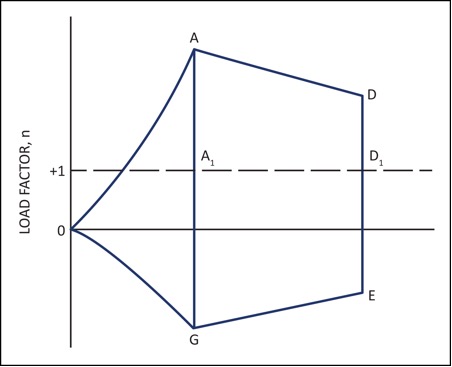 FIGURE 1 PITCHING MANOUEVRES