Light
Dark
System
Log In
Loading...
Compare / EASA/
Incorporated Amendments
/
Compare & Highlight Differences
AMC No 2 to 27.351 Yaw manoeuvre conditions
Available versions for ERULES-1963177438-6698
ED Decision 2016/024/R
found in: CS-27 Amdt 9 - Small Rotorcraft (Dec 2021)
From
CS-27 Amdt 10 - Sm... (Feb 2023)
CS-27 Amdt 9 - Sma... (Dec 2021)
From section
To
CS-27 Amdt 10 - Sm... (Feb 2023)
CS-27 Amdt 9 - Sma... (Dec 2021)
To section
No visible text changes
0 removals
0 additions
View
Rich
Plain
Sync scrolling
Share
From
Show details
Hide details
To
Show details
Hide details
Version
Show side by side
AMC No 2 to 27.351 Yaw manoeuvre conditions ED Decision 2016/024/R 1. Introduction This AMC provides further guidance and acceptable means of compliance to supplement FAA AC 271B § AC 27.351. § 27.351 to meet the Agency's interpretation of [CS 27.351](#_DxCrossRefBm472493256). As such it should be used in conjunction with the FAA AC but take precedence over it, where stipulated, in the showing of compliance. Specifically, this AMC addresses two areas where the FAA AC has been deemed by the Agency as being unclear or at variance to the Agency’s interpretation. These areas are as follows: a. Aerodynamic Loads The certification specification [CS 27.351](#_DxCrossRefBm472493256) provides a minimum safety standard for the design of rotorcraft structural components that are subjected in flight to critical loads combinations of antitorque system thrust (e.g. tail rotor), inertia and aerodynamics. A typical example of these structural components is the tailboom. However, compliance with this standard according to FAA AC may not necessarily be adequate for the design of rotorcraft structural components that are principally subjected in flight to significant aerodynamic loads (e.g. vertical empennage, fins, cowlings and doors). For these components and their supporting structure, suitable design criteria should be developed by the Applicant and agreed with the Agency. In lieu of acceptable design criteria developed by the applicant, a suitable combination of sideslip angle and airspeed for the design of rotorcraft components subjected to aerodynamic loads may be obtained from a simulation of the yaw manoeuvre of [CS 27.351](#_DxCrossRefBm472493256), starting from the initial directional control input specified in [CS 27.351(b)(1) and (c)(1)](#_DxCrossRefBm472493256), until the rotorcraft reaches the maximum transient sideslip angle (overswing) resulting from its motion around the yaw axis. b. Interaction of System and Structure Maximum displacement of the directional control, except as limited by pilot effort ([CS 27.397(a)](#_DxCrossRefBm472493272)), is required for the conditions cited in the certification specification. In the load evaluation credit may be taken for consideration of the effects of control system limiting devices. However, the probability of failure or malfunction of these system(s) should also be considered and if it is shown not to be extremely improbable then further load conditions with the system in the failed state should be evaluated. This evaluation may include Flight Manual Limitations, if failure of the system is reliably indicated to the crew. A yaw limiting device is a typical example of a system whose failed condition should be investigated in the assessment of the loads requested by [CS 27.351](#_DxCrossRefBm472493256). An acceptable methodology to investigate the effects of all system failures not shown to be extremely improbable on the loading conditions of [CS 27.351](#_DxCrossRefBm472493256) is as follows: (i) With the system in the failed state and considering any appropriate reconfiguration and flight limitations, it should be shown that the rotorcraft structure can withstand without failure the loading conditions of [CS 27.351](#_DxCrossRefBm472493256), when the manoeuvre is performed in accordance with the provisions of this AMC. (ii) The factor of safety to apply to the above specified loading conditions to comply with [CS 27.305](#_DxCrossRefBm472493264) is defined in the figure below. 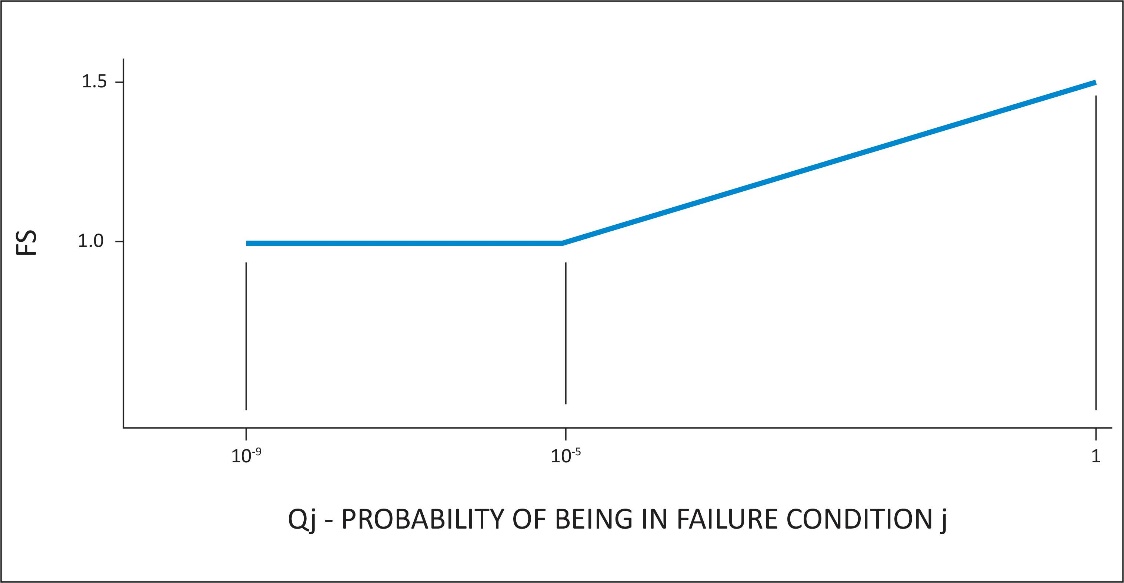 Qj = (Tj)(Pj) where: Tj = Average flight time spent with a failed limiting system j (in hours) Pj = Probability of occurrence of failure of control limiting system j (per hour) Note: If Pj is greater than 1x10³ per flight hour then a 1.5 factor of safety should be applied to all limit load conditions evaluated for the system failure under consideration. [Amdt 27/2] [Amdt 27/4]
AMC No 2 to 27.351 Yaw manoeuvre conditions ED Decision 2016/024/R 1. Introduction This AMC provides further guidance and acceptable means of compliance to supplement FAA AC 271B § AC 27.351. § 27.351 to meet the Agency's interpretation of [CS 27.351](#_DxCrossRefBm8893814). As such it should be used in conjunction with the FAA AC but take precedence over it, where stipulated, in the showing of compliance. Specifically, this AMC addresses two areas where the FAA AC has been deemed by the Agency as being unclear or at variance to the Agency’s interpretation. These areas are as follows: a. Aerodynamic Loads The certification specification [CS 27.351](#_DxCrossRefBm8893814) provides a minimum safety standard for the design of rotorcraft structural components that are subjected in flight to critical loads combinations of antitorque system thrust (e.g. tail rotor), inertia and aerodynamics. A typical example of these structural components is the tailboom. However, compliance with this standard according to FAA AC may not necessarily be adequate for the design of rotorcraft structural components that are principally subjected in flight to significant aerodynamic loads (e.g. vertical empennage, fins, cowlings and doors). For these components and their supporting structure, suitable design criteria should be developed by the Applicant and agreed with the Agency. In lieu of acceptable design criteria developed by the applicant, a suitable combination of sideslip angle and airspeed for the design of rotorcraft components subjected to aerodynamic loads may be obtained from a simulation of the yaw manoeuvre of [CS 27.351](#_DxCrossRefBm8893814), starting from the initial directional control input specified in [CS 27.351(b)(1) and (c)(1)](#_DxCrossRefBm8893814), until the rotorcraft reaches the maximum transient sideslip angle (overswing) resulting from its motion around the yaw axis. b. Interaction of System and Structure Maximum displacement of the directional control, except as limited by pilot effort ([CS 27.397(a)](#_DxCrossRefBm8893838)), is required for the conditions cited in the certification specification. In the load evaluation credit may be taken for consideration of the effects of control system limiting devices. However, the probability of failure or malfunction of these system(s) should also be considered and if it is shown not to be extremely improbable then further load conditions with the system in the failed state should be evaluated. This evaluation may include Flight Manual Limitations, if failure of the system is reliably indicated to the crew. A yaw limiting device is a typical example of a system whose failed condition should be investigated in the assessment of the loads requested by [CS 27.351](#_DxCrossRefBm8893814). An acceptable methodology to investigate the effects of all system failures not shown to be extremely improbable on the loading conditions of [CS 27.351](#_DxCrossRefBm8893814) is as follows: (i) With the system in the failed state and considering any appropriate reconfiguration and flight limitations, it should be shown that the rotorcraft structure can withstand without failure the loading conditions of [CS 27.351](#_DxCrossRefBm8893814), when the manoeuvre is performed in accordance with the provisions of this AMC. (ii) The factor of safety to apply to the above specified loading conditions to comply with [CS 27.305](#_DxCrossRefBm8893823) is defined in the figure below. 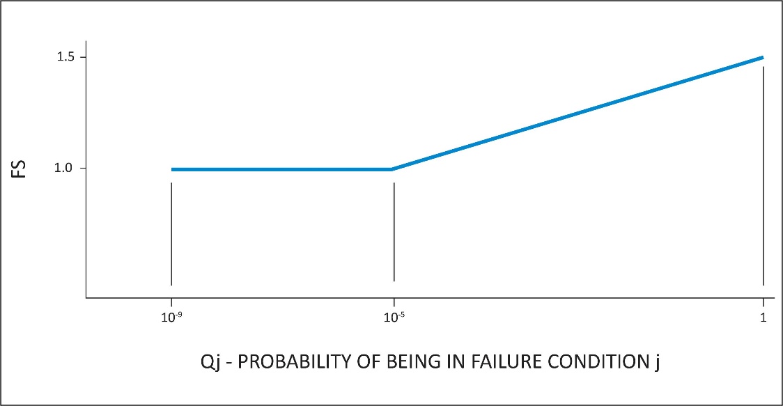 Qj = (Tj)(Pj) where: Tj = Average flight time spent with a failed limiting system j (in hours) Pj = Probability of occurrence of failure of control limiting system j (per hour) Note: If Pj is greater than 1x10³ per flight hour then a 1.5 factor of safety should be applied to all limit load conditions evaluated for the system failure under consideration. [Amdt 27/2] [Amdt 27/4]