Light
Dark
System
Log In
Loading...
Compare / EASA/
Incorporated Amendments
/
Compare & Highlight Differences
CS 29.339 Resultant limit manoeuvring loads
Available versions for ERULES-1963177438-5608
ED Decision 2003/16/RM
found in: CS-29 Amdt 10 - Large Rotercraft (Jan 2023)
From
CS-29 Amdt 12 - La... (Mar 2026)
CS-29 Amdt 11 - La... (Feb 2023)
CS-29 Amdt 10 - La... (Jan 2023)
From section
To
CS-29 Amdt 12 - La... (Mar 2026)
CS-29 Amdt 11 - La... (Feb 2023)
CS-29 Amdt 10 - La... (Jan 2023)
To section
No visible text changes
0 removals
0 additions
View
Rich
Plain
Sync scrolling
Share
From
Show details
Hide details
To
Show details
Hide details
Version
Show side by side
CS 29.339 Resultant limit manoeuvring loads ED Decision 2003/16/RM The loads resulting from the application of limit manoeuvring load factors are assumed to act at the centre of each rotor hub and at each auxiliary lifting surface, and to act in directions and with distributions of load among the rotors and auxiliary lifting surfaces, so as to represent each critical manoeuvring condition, including power-on and power-off flight with the maximum design rotor tip speed ratio. The rotor tip speed ratio is the ratio of the rotorcraft flight velocity component in the plane of the rotor disc to the rotational tip speed of the rotor blades and is expressed as follows: 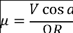 where: V = The airspeed along the flight path (m/s (fps)); a = The angle between the projection, in the plane of symmetry, of the axis of no feathering and a line perpendicular to the flight path (radians, positive when axis is pointing aft); Ω = The angular velocity of rotor (radians per second); and R = The rotor radius (m (ft)).
CS 29.339 Resultant limit manoeuvring loads ED Decision 2003/16/RM The loads resulting from the application of limit manoeuvring load factors are assumed to act at the centre of each rotor hub and at each auxiliary lifting surface, and to act in directions and with distributions of load among the rotors and auxiliary lifting surfaces, so as to represent each critical manoeuvring condition, including power-on and power-off flight with the maximum design rotor tip speed ratio. The rotor tip speed ratio is the ratio of the rotorcraft flight velocity component in the plane of the rotor disc to the rotational tip speed of the rotor blades and is expressed as follows:  where: V = The airspeed along the flight path (m/s (fps)); a = The angle between the projection, in the plane of symmetry, of the axis of no feathering and a line perpendicular to the flight path (radians, positive when axis is pointing aft); Ω = The angular velocity of rotor (radians per second); and R = The rotor radius (m (ft)).
#### CS 29.339 Resultant limit manoeuvring loads *ED Decision 2003/16/RM* The loads resulting from the application of limit manoeuvring load factors are assumed to act at the centre of each rotor hub and at each auxiliary lifting surface, and to act in directions and with distributions of load among the rotors and auxiliary lifting surfaces, so as to represent each critical manoeuvring condition, including power-on and power-off flight with the maximum design rotor tip speed ratio. The rotor tip speed ratio is the ratio of the rotorcraft flight velocity component in the plane of the rotor disc to the rotational tip speed of the rotor blades and is expressed as follows: where: V = The airspeed along the flight path (m/s (fps)); a = The angle between the projection, in the plane of symmetry, of the axis of no feathering and a line perpendicular to the flight path (radians, positive when axis is pointing aft); Ω = The angular velocity of rotor (radians per second); and R = The rotor radius (m (ft)).