Light
Dark
System
Log In
Loading...
Compare / EASA/
Incorporated Amendments
/
Compare & Highlight Differences
GM1 26.110(e)(4) Emergency Exit Markings
Available versions for ERULES-1963177438-2937
ED Decision 2015/013/R
found in: CS-26 Additional Airworthiness Specifications for Operations (No 2015/640) Part-26 (Mar 2023)
From
CS-26 Additional A... (Oct 2025)
CS-26 Additional A... (Mar 2023)
From section
To
CS-26 Additional A... (Oct 2025)
CS-26 Additional A... (Mar 2023)
To section
No visible text changes
0 removals
0 additions
View
Rich
Plain
Sync scrolling
Share
From
Show details
Hide details
To
Show details
Hide details
Version
Show side by side
GM1 26.110(e)(4) Emergency Exit Markings ED Decision 2015/013/R The indicating markings for all Type II and larger passenger emergency exit unlocking handle motions should conform to the general shapes and dimensions indicated by Figures 1 and 2. NOTE: As far as is practicable the markings should be located to avoid obscuring viewing windows located on or alongside the exits, or coincidence with any other required marking or safety feature. FIGURE 1 EXAMPLE MARKING FOR INDICATION OF LINEAR OPENING MOTION Where practical and unambiguous arrow point and base of arrow shaft to be within ±25 mm (1 inch) 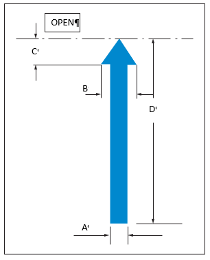 of fully unlocked and fully locked positions respectively DIMENSIONS A = 19 mm (0•75") minimum B = 2 x A C = B (recommended) D = Indicative of the full extent of handle travel (each installation to be individually assessed) FIGURE 2 EXAMPLE MARKING FOR INDICATION OF ROTARY OPENING MOTION Arrow point and base of arrow shaft to be within ±25 mm (1 inch) of fully unlocked and fully locked positions respectively 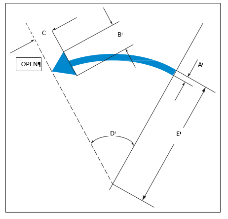 DIMENSIONS A = 19 mm (0•75") minimum B = 2 x A C = B (recommended) D = Full extent of handle centreline travel E = Three quarters of handle length (where practicable)
##### GM1 26.110(e)(4) Emergency Exit Markings *ED Decision 2015/013/R* The indicating markings for all Type II and larger passenger emergency exit unlocking handle motions should conform to the general shapes and dimensions indicated by Figures 1 and 2. NOTE: As far as is practicable the markings should be located to avoid obscuring viewing windows located on or alongside the exits, or coincidence with any other required marking or safety feature. **FIGURE 1** **EXAMPLE MARKING FOR INDICATION OF LINEAR OPENING MOTION** Where practical and unambiguous arrow point and base of arrow shaft to be within ±25 mm (1 inch) 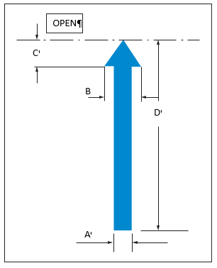 of fully unlocked and fully locked positions respectively *DIMENSIONS* *A = 19 mm (0•75") minimum* *B = 2 x A* *C = B (recommended)* *D = Indicative of the full extent of handle travel (each installation to be individually assessed)* **FIGURE 2** **EXAMPLE MARKING FOR INDICATION OF ROTARY OPENING MOTION** Arrow point and base of arrow shaft to be within ±25 mm (1 inch) of fully unlocked and fully locked positions respectively 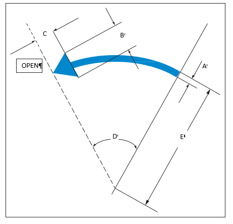 *DIMENSIONS* *A = 19 mm (0•75") minimum* *B = 2 x A* *C = B (recommended)* *D = Full extent of handle centreline travel* *E = Three quarters of handle length (where practicable)*