Light
Dark
System
Log In
Loading...
Compare / EASA/
Incorporated Amendments
/
Compare & Highlight Differences
GM6 ADR.OPS.B.010(a)(2) Rescue and firefighting services
Available versions for ERULES-1963177438-2860
ED Decision 2016/009/R
found in: Aerodromes (139/2014) Part-ADR.AR Part-ADR.OR Part-ADR.OPS CS-ADR-DSN CS-HPT-DSN (Dec 2024)
From
Easy Access Rules ... (Mar 2026)
Aerodromes (139/20... (Dec 2024)
Aerodromes (139/20... (Jun 2023)
From section
To
Easy Access Rules ... (Mar 2026)
Aerodromes (139/20... (Dec 2024)
Aerodromes (139/20... (Jun 2023)
To section
No visible text changes
0 removals
0 additions
View
Rich
Plain
Sync scrolling
Share
From
Show details
Hide details
To
Show details
Hide details
Version
Show side by side
GM6 ADR.OPS.B.010(a)(2) Rescue and firefighting services ED Decision 2016/009/R CRITICAL AREA FOR CALCULATING QUANTITIES OF WATER (a) The ICAO critical-area concept is applied for rescuing the occupants of an aeroplane. It seeks to control only that area of fire adjacent to the fuselage. The objective is to safeguard the integrity of the fuselage and maintain tolerable conditions for the occupants of the aeroplane. The size of the controlled area required to achieve this for a specific aeroplane has been determined by experimental means. (b) There is a need to distinguish between the theoretical critical area, within which it may be necessary to control the fire, and the practical critical area, which is representative of actual aeroplane accident conditions. The theoretical critical area serves only as a means of categorising aeroplanes in terms of the magnitude of the potential fire hazard in which they may become involved. It is not intended to represent the average maximum or minimum spill fire size associated with a particular aeroplane. The theoretical critical area is a rectangle having as one dimension the overall length of the aeroplane and as the other dimension a length which varies with the fuselage’s length and width. (c) From experiments performed, it has been established that for an aeroplane with a fuselage length equal to or greater than 24 m, in wind conditions of 16–19 km/h and at right angles to the fuselage, the theoretical critical area extends from the fuselage to a distance of 24 m upwind and 6 m downwind. For smaller aeroplanes, a distance of 6 m on either side is adequate. To provide for a progressive increase in the theoretical critical area however, a transition is used when the fuselage length is between 12 and 24 m. (d) The overall length of the aeroplane is considered appropriate for the theoretical critical area as the entire length of the aeroplane must be protected from burning. If not, the fire might burn through the skin and enter the fuselage. Moreover, other aeroplanes, such as T-tail ones, often have engines or exit points in their extended portion. (e) The formula for the theoretical critical area AT should be the following: <table border="1" cellpadding="0" cellspacing="0" width="566"><tr><td valign="top" width="283"><p align="center"><b>Overall length</b></p></td><td valign="top" width="283"><p align="center"><b>Theoretical critical area A<sub>T</sub></b></p></td></tr><tr><td valign="top" width="283"><p align="center">L < 12 m</p></td><td valign="top" width="283"><p align="center">L × (12 + W)</p></td></tr><tr><td valign="top" width="283"><p align="center">12 m ≤ L < 18 m</p></td><td valign="top" width="283"><p align="center">L × (14 + W)</p></td></tr><tr><td valign="top" width="283"><p align="center">18 m ≤ L < 24 m</p></td><td valign="top" width="283"><p align="center">L × (17 + W)</p></td></tr><tr><td valign="top" width="283"><p align="center">L ≥ 24 m</p></td><td valign="top" width="283"><p align="center">L × (30 + W)</p></td></tr></table> where ‘L’ is the overall length of the aeroplane, and ‘W’ is the maximum width of the aeroplane fuselage. (f) In practice, it is seldom that the entire theoretical critical area is subject to fire; thus, a smaller area for which it is proposed to have firefighting capacity is referred to as the practical critical area. As a result of a statistical analysis of actual aeroplane accidents, the practical critical area AP has been found to be approximately two thirds of the theoretical critical area AT, or  (g) The quantity of water for foam production should be calculated with the following formula: 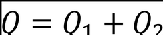 where: — ‘Q’ is the total water required; — ‘Q1’ is the water used to control the fire in the practical critical area; and — ‘Q2’ is the water required after control of the fire has been established, and is needed for maintaining this control and/or extinguishing the remaining fire. (h) The water required for control of the fire in the practical critical area (Q1) may be expressed by the following formula:  where: — ‘Ap’ is the practical critical area; — ‘R’ is the rate of application; and — ‘T’ is the time of application. (i) The amount of water required for Q2 may not be exactly calculated as it depends on a number of variables. The factors considered to be of primary importance are: (1) the maximum gross mass of the aeroplane; (2) the maximum passenger capacity of the aeroplane; (3) the maximum fuel load of the aeroplane; and (4) previous experience (analysis of aeroplane RFF operations). These factors, when plotted on a graph, are used to calculate the total amount of water required for each airport category. The volume of water for Q2, as a percentage of Q1, varies from about 0 % for category 1 aerodromes to about 190 % for a category 10 aerodrome. (j) The relation between Q1 and Q2 for aeroplanes representative of each airport category is shown in the following table: <table border="1" cellpadding="0" cellspacing="0" width="565"><tr><td valign="top" width="283"><p align="center"><b>Aerodrome category</b></p></td><td valign="top" width="283"><p align="center"><b>Q<sub>2</sub> = percentage of Q<sub>1</sub></b></p></td></tr><tr><td valign="top" width="283"><p align="center">1</p></td><td valign="top" width="283"><p align="center">0 %</p></td></tr><tr><td valign="top" width="283"><p align="center">2</p></td><td valign="top" width="283"><p align="center">27 %</p></td></tr><tr><td valign="top" width="283"><p align="center">3</p></td><td valign="top" width="283"><p align="center">30 %</p></td></tr><tr><td valign="top" width="283"><p align="center">4</p></td><td valign="top" width="283"><p align="center">58 %</p></td></tr><tr><td valign="top" width="283"><p align="center">5</p></td><td valign="top" width="283"><p align="center">75 %</p></td></tr><tr><td valign="top" width="283"><p align="center">6</p></td><td valign="top" width="283"><p align="center">100 %</p></td></tr><tr><td valign="top" width="283"><p align="center">7</p></td><td valign="top" width="283"><p align="center">129 %</p></td></tr><tr><td valign="top" width="283"><p align="center">8</p></td><td valign="top" width="283"><p align="center">152 %</p></td></tr><tr><td valign="top" width="283"><p align="center">9</p></td><td valign="top" width="283"><p align="center">170 %</p></td></tr><tr><td valign="top" width="283"><p align="center">10</p></td><td valign="top" width="283"><p align="center">190 %</p></td></tr></table>
GM6 ADR.OPS.B.010(a)(2) Rescue and firefighting services ED Decision 2016/009/R CRITICAL AREA FOR CALCULATING QUANTITIES OF WATER (a) The ICAO critical-area concept is applied for rescuing the occupants of an aeroplane. It seeks to control only that area of fire adjacent to the fuselage. The objective is to safeguard the integrity of the fuselage and maintain tolerable conditions for the occupants of the aeroplane. The size of the controlled area required to achieve this for a specific aeroplane has been determined by experimental means. (b) There is a need to distinguish between the theoretical critical area, within which it may be necessary to control the fire, and the practical critical area, which is representative of actual aeroplane accident conditions. The theoretical critical area serves only as a means of categorising aeroplanes in terms of the magnitude of the potential fire hazard in which they may become involved. It is not intended to represent the average maximum or minimum spill fire size associated with a particular aeroplane. The theoretical critical area is a rectangle having as one dimension the overall length of the aeroplane and as the other dimension a length which varies with the fuselage’s length and width. (c) From experiments performed, it has been established that for an aeroplane with a fuselage length equal to or greater than 24 m, in wind conditions of 16–19 km/h and at right angles to the fuselage, the theoretical critical area extends from the fuselage to a distance of 24 m upwind and 6 m downwind. For smaller aeroplanes, a distance of 6 m on either side is adequate. To provide for a progressive increase in the theoretical critical area however, a transition is used when the fuselage length is between 12 and 24 m. (d) The overall length of the aeroplane is considered appropriate for the theoretical critical area as the entire length of the aeroplane must be protected from burning. If not, the fire might burn through the skin and enter the fuselage. Moreover, other aeroplanes, such as T-tail ones, often have engines or exit points in their extended portion. (e) The formula for the theoretical critical area AT should be the following: <table border="1" cellpadding="0" cellspacing="0" width="566"><tr><td valign="top" width="283"><p align="center"><b>Overall length</b></p></td><td valign="top" width="283"><p align="center"><b>Theoretical critical area A<sub>T</sub></b></p></td></tr><tr><td valign="top" width="283"><p align="center">L < 12 m</p></td><td valign="top" width="283"><p align="center">L × (12 + W)</p></td></tr><tr><td valign="top" width="283"><p align="center">12 m ≤ L < 18 m</p></td><td valign="top" width="283"><p align="center">L × (14 + W)</p></td></tr><tr><td valign="top" width="283"><p align="center">18 m ≤ L < 24 m</p></td><td valign="top" width="283"><p align="center">L × (17 + W)</p></td></tr><tr><td valign="top" width="283"><p align="center">L ≥ 24 m</p></td><td valign="top" width="283"><p align="center">L × (30 + W)</p></td></tr></table> where ‘L’ is the overall length of the aeroplane, and ‘W’ is the maximum width of the aeroplane fuselage. (f) In practice, it is seldom that the entire theoretical critical area is subject to fire; thus, a smaller area for which it is proposed to have firefighting capacity is referred to as the practical critical area. As a result of a statistical analysis of actual aeroplane accidents, the practical critical area AP has been found to be approximately two thirds of the theoretical critical area AT, or  (g) The quantity of water for foam production should be calculated with the following formula: 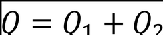 where: — ‘Q’ is the total water required; — ‘Q1’ is the water used to control the fire in the practical critical area; and — ‘Q2’ is the water required after control of the fire has been established, and is needed for maintaining this control and/or extinguishing the remaining fire. (h) The water required for control of the fire in the practical critical area (Q1) may be expressed by the following formula:  where: — ‘Ap’ is the practical critical area; — ‘R’ is the rate of application; and — ‘T’ is the time of application. (i) The amount of water required for Q2 may not be exactly calculated as it depends on a number of variables. The factors considered to be of primary importance are: (1) the maximum gross mass of the aeroplane; (2) the maximum passenger capacity of the aeroplane; (3) the maximum fuel load of the aeroplane; and (4) previous experience (analysis of aeroplane RFF operations). These factors, when plotted on a graph, are used to calculate the total amount of water required for each airport category. The volume of water for Q2, as a percentage of Q1, varies from about 0 % for category 1 aerodromes to about 190 % for a category 10 aerodrome. (j) The relation between Q1 and Q2 for aeroplanes representative of each airport category is shown in the following table: <table border="1" cellpadding="0" cellspacing="0" width="565"><tr><td valign="top" width="283"><p align="center"><b>Aerodrome category</b></p></td><td valign="top" width="283"><p align="center"><b>Q<sub>2</sub> = percentage of Q<sub>1</sub></b></p></td></tr><tr><td valign="top" width="283"><p align="center">1</p></td><td valign="top" width="283"><p align="center">0 %</p></td></tr><tr><td valign="top" width="283"><p align="center">2</p></td><td valign="top" width="283"><p align="center">27 %</p></td></tr><tr><td valign="top" width="283"><p align="center">3</p></td><td valign="top" width="283"><p align="center">30 %</p></td></tr><tr><td valign="top" width="283"><p align="center">4</p></td><td valign="top" width="283"><p align="center">58 %</p></td></tr><tr><td valign="top" width="283"><p align="center">5</p></td><td valign="top" width="283"><p align="center">75 %</p></td></tr><tr><td valign="top" width="283"><p align="center">6</p></td><td valign="top" width="283"><p align="center">100 %</p></td></tr><tr><td valign="top" width="283"><p align="center">7</p></td><td valign="top" width="283"><p align="center">129 %</p></td></tr><tr><td valign="top" width="283"><p align="center">8</p></td><td valign="top" width="283"><p align="center">152 %</p></td></tr><tr><td valign="top" width="283"><p align="center">9</p></td><td valign="top" width="283"><p align="center">170 %</p></td></tr><tr><td valign="top" width="283"><p align="center">10</p></td><td valign="top" width="283"><p align="center">190 %</p></td></tr></table>
##### GM6 ADR.OPS.B.010(a)(2) Rescue and firefighting services *ED Decision 2016/009/R* **CRITICAL AREA FOR CALCULATING QUANTITIES OF WATER** (a) The ICAO critical-area concept is applied for rescuing the occupants of an aeroplane. It seeks to control only that area of fire adjacent to the fuselage. The objective is to safeguard the integrity of the fuselage and maintain tolerable conditions for the occupants of the aeroplane. The size of the controlled area required to achieve this for a specific aeroplane has been determined by experimental means. (b) There is a need to distinguish between the theoretical critical area, within which it may be necessary to control the fire, and the practical critical area, which is representative of actual aeroplane accident conditions. The theoretical critical area serves only as a means of categorising aeroplanes in terms of the magnitude of the potential fire hazard in which they may become involved. It is not intended to represent the average maximum or minimum spill fire size associated with a particular aeroplane. The theoretical critical area is a rectangle having as one dimension the overall length of the aeroplane and as the other dimension a length which varies with the fuselage’s length and width. (c) From experiments performed, it has been established that for an aeroplane with a fuselage length equal to or greater than 24 m, in wind conditions of 16–19 km/h and at right angles to the fuselage, the theoretical critical area extends from the fuselage to a distance of 24 m upwind and 6 m downwind. For smaller aeroplanes, a distance of 6 m on either side is adequate. To provide for a progressive increase in the theoretical critical area however, a transition is used when the fuselage length is between 12 and 24 m. (d) The overall length of the aeroplane is considered appropriate for the theoretical critical area as the entire length of the aeroplane must be protected from burning. If not, the fire might burn through the skin and enter the fuselage. Moreover, other aeroplanes, such as T-tail ones, often have engines or exit points in their extended portion. (e) The formula for the theoretical critical area AT should be the following: <table bgcolor="#d9d9d9" cellpadding="7" cellspacing="0"> <col/> <col/> <tr valign="top"> <td bgcolor="#808080"><p align="center"> <b>Overall length</b></p> </td> <td bgcolor="#808080"><p align="center"> <b>Theoretical critical area A<sub>T</sub></b></p> </td> </tr> <tr valign="top"> <td bgcolor="#d9d9d9"><p align="center"> L < 12 m</p> </td> <td bgcolor="#d9d9d9"><p align="center"> L × (12 + W)</p> </td> </tr> <tr valign="top"> <td bgcolor="#d9d9d9"><p align="center"> 12 m ≤ L < 18 m</p> </td> <td bgcolor="#d9d9d9"><p align="center"> L × (14 + W)</p> </td> </tr> <tr valign="top"> <td bgcolor="#d9d9d9"><p align="center"> 18 m ≤ L < 24 m</p> </td> <td bgcolor="#d9d9d9"><p align="center"> L × (17 + W)</p> </td> </tr> <tr valign="top"> <td bgcolor="#d9d9d9"><p align="center"> L ≥ 24 m</p> </td> <td bgcolor="#d9d9d9"><p align="center"> L × (30 + W)</p> </td> </tr> </table> where ‘L’ is the overall length of the aeroplane, and ‘W’ is the maximum width of the aeroplane fuselage. (f) In practice, it is seldom that the entire theoretical critical area is subject to fire; thus, a smaller area for which it is proposed to have firefighting capacity is referred to as the practical critical area. As a result of a statistical analysis of actual aeroplane accidents, the practical critical area AP has been found to be approximately two thirds of the theoretical critical area AT, or (g) The quantity of water for foam production should be calculated with the following formula: where: — ‘Q’ is the total water required; — ‘Q1’ is the water used to control the fire in the practical critical area; and — ‘Q2’ is the water required after control of the fire has been established, and is needed for maintaining this control and/or extinguishing the remaining fire. (h) The water required for control of the fire in the practical critical area (Q1) may be expressed by the following formula: where: — ‘Ap’ is the practical critical area; — ‘R’ is the rate of application; and — ‘T’ is the time of application. (i) The amount of water required for Q2 may not be exactly calculated as it depends on a number of variables. The factors considered to be of primary importance are: (1) the maximum gross mass of the aeroplane; (2) the maximum passenger capacity of the aeroplane; (3) the maximum fuel load of the aeroplane; and (4) previous experience (analysis of aeroplane RFF operations). These factors, when plotted on a graph, are used to calculate the total amount of water required for each airport category. The volume of water for Q2, as a percentage of Q1, varies from about 0 % for category 1 aerodromes to about 190 % for a category 10 aerodrome. (j) The relation between Q1 and Q2 for aeroplanes representative of each airport category is shown in the following table: <table bgcolor="#d9d9d9" cellpadding="7" cellspacing="0"> <col/> <col/> <tr valign="top"> <td bgcolor="#808080"><p align="center"> <b>Aerodrome category</b></p> </td> <td bgcolor="#808080"><p align="center"> <b>Q<sub>2</sub> = percentage of Q<sub>1</sub></b></p> </td> </tr> <tr valign="top"> <td bgcolor="#d9d9d9"><p align="center"> 1</p> </td> <td bgcolor="#d9d9d9"><p align="center"> 0 %</p> </td> </tr> <tr valign="top"> <td bgcolor="#d9d9d9"><p align="center"> 2</p> </td> <td bgcolor="#d9d9d9"><p align="center"> 27 %</p> </td> </tr> <tr valign="top"> <td bgcolor="#d9d9d9"><p align="center"> 3</p> </td> <td bgcolor="#d9d9d9"><p align="center"> 30 %</p> </td> </tr> <tr valign="top"> <td bgcolor="#d9d9d9"><p align="center"> 4</p> </td> <td bgcolor="#d9d9d9"><p align="center"> 58 %</p> </td> </tr> <tr valign="top"> <td bgcolor="#d9d9d9"><p align="center"> 5</p> </td> <td bgcolor="#d9d9d9"><p align="center"> 75 %</p> </td> </tr> <tr valign="top"> <td bgcolor="#d9d9d9"><p align="center"> 6</p> </td> <td bgcolor="#d9d9d9"><p align="center"> 100 %</p> </td> </tr> <tr valign="top"> <td bgcolor="#d9d9d9"><p align="center"> 7</p> </td> <td bgcolor="#d9d9d9"><p align="center"> 129 %</p> </td> </tr> <tr valign="top"> <td bgcolor="#d9d9d9"><p align="center"> 8</p> </td> <td bgcolor="#d9d9d9"><p align="center"> 152 %</p> </td> </tr> <tr valign="top"> <td bgcolor="#d9d9d9"><p align="center"> 9</p> </td> <td bgcolor="#d9d9d9"><p align="center"> 170 %</p> </td> </tr> <tr valign="top"> <td bgcolor="#d9d9d9"><p align="center"> 10</p> </td> <td bgcolor="#d9d9d9"><p align="center"> 190 %</p> </td> </tr> </table>