Light
Dark
System
Log In
Loading...
Compare / EASA/
Incorporated Amendments
/
Compare & Highlight Differences
GM1 ADR-DSN.B.075 Distance between slope changes on runways
Available versions for ERULES-1963177438-2360
ED Decision 2014/013/R
found in: Aerodromes (139/2014) Part-ADR.AR Part-ADR.OR Part-ADR.OPS CS-ADR-DSN CS-HPT-DSN (Dec 2024)
From
Easy Access Rules ... (Mar 2026)
Aerodromes (139/20... (Dec 2024)
Aerodromes (139/20... (Jun 2023)
From section
To
Easy Access Rules ... (Mar 2026)
Aerodromes (139/20... (Dec 2024)
Aerodromes (139/20... (Jun 2023)
To section
No visible text changes
0 removals
0 additions
View
Rich
Plain
Sync scrolling
Share
From
Show details
Hide details
To
Show details
Hide details
Version
Show side by side
GM1 ADR-DSN.B.075 Distance between slope changes on runways ED Decision 2014/013/R The following example illustrates how the distance between slope changes is to be determined (see Figure GM-B-2): D for a runway where the code number is 3 should be at least: 15 000 (│x – y│ + │y – z│) m │x – y│ being the absolute numerical value of x – y │y – z│ being the absolute numerical value of y – z Assuming x = +0.01 y = –0.005 z = +0.005 then │x – y│ = 0.015 then │y – z│ = 0.01 To comply with the specifications, D should be not less than: 15 000 (0.015 + 0.01) m, that is, 15 000 × 0.025 = 375 m When a runway is planned that should combine the extreme values for the slopes and changes in slope permitted, as prescribed in [CS ADR-DSN.B.060](#_DxCrossRefBm151830599) to [CS ADR-DSN.B.080](#_DxCrossRefBm151830607), a study should be made to ensure that the resulting surface profile should not hamper the operation of aeroplanes. 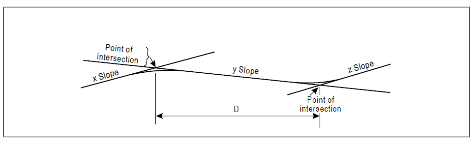 Figure GM-B-2. Profile on centre line of runway
GM1 ADR-DSN.B.075 Distance between slope changes on runways ED Decision 2014/013/R The following example illustrates how the distance between slope changes is to be determined (see Figure GM-B-2): D for a runway where the code number is 3 should be at least: 15 000 (│x – y│ + │y – z│) m │x – y│ being the absolute numerical value of x – y │y – z│ being the absolute numerical value of y – z Assuming x = +0.01 y = –0.005 z = +0.005 then │x – y│ = 0.015 then │y – z│ = 0.01 To comply with the specifications, D should be not less than: 15 000 (0.015 + 0.01) m, that is, 15 000 × 0.025 = 375 m When a runway is planned that should combine the extreme values for the slopes and changes in slope permitted, as prescribed in [CS ADR-DSN.B.060](#_DxCrossRefBm1800047461) to [CS ADR-DSN.B.080](#_DxCrossRefBm1800047469), a study should be made to ensure that the resulting surface profile should not hamper the operation of aeroplanes. 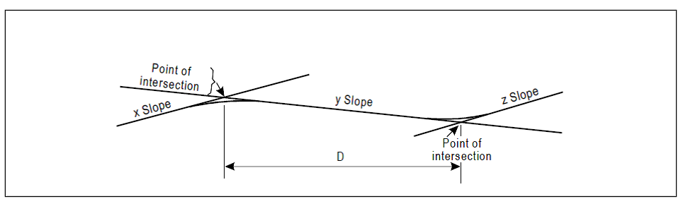 Figure GM-B-2. Profile on centre line of runway
##### GM1 ADR-DSN.B.075 Distance between slope changes on runways *ED Decision 2014/013/R* The following example illustrates how the distance between slope changes is to be determined (see Figure GM-B-2): D for a runway where the code number is 3 should be at least: 15 000 (│x – y│ + │y – z│) m │x – y│ being the absolute numerical value of x – y │y – z│ being the absolute numerical value of y – z Assuming x = +0.01 y = –0.005 z = +0.005 then │x – y│ = 0.015 then │y – z│ = 0.01 To comply with the specifications, D should be not less than: 15 000 (0.015 + 0.01) m, that is, 15 000 × 0.025 = 375 m When a runway is planned that should combine the extreme values for the slopes and changes in slope permitted, as prescribed in [CS ADR-DSN.B.060](#_DxCrossRefBm1262885038) to [CS ADR-DSN.B.080](#_DxCrossRefBm1262885046), a study should be made to ensure that the resulting surface profile should not hamper the operation of aeroplanes. 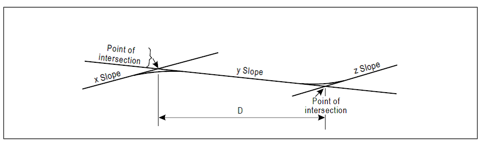 ***Figure GM-B-2. Profile on centre line of runway***