Light
Dark
System
Log In
Loading...
Compare / EASA/
Incorporated Amendments
/
Compare & Highlight Differences
CS ADR-DSN.M.630 Precision approach Category I lighting system
Available versions for ERULES-1963177438-2272
ED Decision 2021/004/R
found in: Aerodromes (139/2014) Part-ADR.AR Part-ADR.OR Part-ADR.OPS CS-ADR-DSN CS-HPT-DSN (Dec 2024)
From
Easy Access Rules ... (Mar 2026)
Aerodromes (139/20... (Dec 2024)
Aerodromes (139/20... (Jun 2023)
From section
To
Easy Access Rules ... (Mar 2026)
Aerodromes (139/20... (Dec 2024)
Aerodromes (139/20... (Jun 2023)
To section
No visible text changes
0 removals
0 additions
View
Rich
Plain
Sync scrolling
Share
From
Show details
Hide details
To
Show details
Hide details
Version
Show side by side
CS ADR-DSN.M.630 Precision approach Category I lighting system ED Decision 2021/004/R (a) The safety objective of the approach lighting system is to provide alignment and roll guidance, and limited distance-to-go information to enable safe approach to a runway. (b) Location and composition (1) General: A precision approach Category I lighting system should consist of a row of lights on the extended centre line of the runway extending wherever possible, over a distance of 900 m from the runway threshold with a row of lights forming a crossbar 30 m in length at a distance of 300 m from the runway threshold (see Figure M-2). (2) Crossbar lights: The lights forming the crossbar should be as close as practicable in a horizontal straight line at right angles to, and bisected by, the line of the centre line lights. The lights of the crossbar should be spaced so as to produce a linear effect, except that gaps may be left on each side of the centre line. These gaps should be kept to a minimum to meet local requirements and each should not exceed 6 m. (3) Centre line lights: The lights forming the centre line should be placed at longitudinal intervals of 30 m with the innermost light located 30 m from the threshold. (4) The system should lie as nearly as practicable in the horizontal plane passing through the threshold, provided that: (i) no object other than an ILS or MLS azimuth antenna should protrude through the plane of the approach lights within a distance of 60 m from the centre line of the system; and (ii) no light other than a light located within the central part of a crossbar or a centre line barrette (not their extremities) should be screened from an approaching aircraft. (iii) Any ILS or MLS azimuth antenna protruding through the plane of the lights should be treated as an obstacle and marked and lighted accordingly. (c) Characteristics: (1) The centre line and crossbar lights of a precision approach Category I lighting system should be fixed lights showing variable white. Each centre line light position should consist of either: (i) a single light source in the innermost 300 m of the centre line, two light sources in the central 300 m of the centre line, and three light sources in the outer 300 m of the centre line to provide distance information; or (ii) a barrette. (2) Where the serviceability level of the approach lights specified as a maintenance objective in [ADR.OPS.C.015](#_DxCrossRefBm151830496) can be demonstrated, each centre line light position should consist of either: (i) a single light source; or (ii) a barrette. When barrettes are composed of lights approximating to point sources, the lights should be uniformly spaced at intervals of not more than 1.5 m. The barrettes should be at least 4 m in length. (3) If the centre line consists of lights as described in paragraph (c)(1)(i) or (c)(2)(i) above, additional crossbars of lights to the crossbar provided at 300 m from the threshold should be provided at 150 m, 450 m, 600 m and 750 m from the threshold. The lights forming each crossbar should be as nearly as practicable in a horizontal straight line at right angles to, and bisected by, the line of the centre line lights. The lights should be spaced so as to produce a linear effect, except that gaps may be left on each side of the centre line. These gaps should be kept to a minimum to meet local requirements and each should not exceed 6 m. (4) Where the additional crossbars are incorporated in the system, the outer ends of the crossbars should lie on two straight lines that either are parallel to the line of the centre line lights or converge to meet the runway centre line 300 m upwind from threshold. (5) The characteristics of lights should be in accordance with the specifications in [CS ADR-DSN.U.940](#_DxCrossRefBm151830505), Figure U-5. The chromaticity of lights should be in accordance with the specifications in[CS ADR-DSN.U.930](#_DxCrossRefBm151830859) and Figure U-1A or U-1B, as appropriate. (6) If the centre line consists of barrettes as described in paragraph (c)(1)(ii) or (c)(2)(ii) above, each barrette should be supplemented by a flashing light, except where such lighting is considered unnecessary taking into account the characteristics of the system, and the nature of the meteorological conditions. (7) Each flashing light, as described in paragraph (c)(6), should be flashed twice a second in sequence, beginning with the outermost light and progressing toward the threshold to the innermost light of the system. The design of the electrical circuit should be such that these lights can be operated independently of the other lights of the approach lighting system. 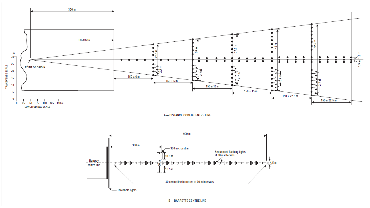 Figure M-2. Precision approach Category I lighting systems [Issue: ADR-DSN/3] [Issue: ADR-DSN/4] [Issue: ADR-DSN/5]
CS ADR-DSN.M.630 Precision approach Category I lighting system ED Decision 2021/004/R (a) The safety objective of the approach lighting system is to provide alignment and roll guidance, and limited distance-to-go information to enable safe approach to a runway. (b) Location and composition (1) General: A precision approach Category I lighting system should consist of a row of lights on the extended centre line of the runway extending wherever possible, over a distance of 900 m from the runway threshold with a row of lights forming a crossbar 30 m in length at a distance of 300 m from the runway threshold (see Figure M-2). (2) Crossbar lights: The lights forming the crossbar should be as close as practicable in a horizontal straight line at right angles to, and bisected by, the line of the centre line lights. The lights of the crossbar should be spaced so as to produce a linear effect, except that gaps may be left on each side of the centre line. These gaps should be kept to a minimum to meet local requirements and each should not exceed 6 m. (3) Centre line lights: The lights forming the centre line should be placed at longitudinal intervals of 30 m with the innermost light located 30 m from the threshold. (4) The system should lie as nearly as practicable in the horizontal plane passing through the threshold, provided that: (i) no object other than an ILS or MLS azimuth antenna should protrude through the plane of the approach lights within a distance of 60 m from the centre line of the system; and (ii) no light other than a light located within the central part of a crossbar or a centre line barrette (not their extremities) should be screened from an approaching aircraft. (iii) Any ILS or MLS azimuth antenna protruding through the plane of the lights should be treated as an obstacle and marked and lighted accordingly. (c) Characteristics: (1) The centre line and crossbar lights of a precision approach Category I lighting system should be fixed lights showing variable white. Each centre line light position should consist of either: (i) a single light source in the innermost 300 m of the centre line, two light sources in the central 300 m of the centre line, and three light sources in the outer 300 m of the centre line to provide distance information; or (ii) a barrette. (2) Where the serviceability level of the approach lights specified as a maintenance objective in [ADR.OPS.C.015](#_DxCrossRefBm1800047358) can be demonstrated, each centre line light position should consist of either: (i) a single light source; or (ii) a barrette. When barrettes are composed of lights approximating to point sources, the lights should be uniformly spaced at intervals of not more than 1.5 m. The barrettes should be at least 4 m in length. (3) If the centre line consists of lights as described in paragraph (c)(1)(i) or (c)(2)(i) above, additional crossbars of lights to the crossbar provided at 300 m from the threshold should be provided at 150 m, 450 m, 600 m and 750 m from the threshold. The lights forming each crossbar should be as nearly as practicable in a horizontal straight line at right angles to, and bisected by, the line of the centre line lights. The lights should be spaced so as to produce a linear effect, except that gaps may be left on each side of the centre line. These gaps should be kept to a minimum to meet local requirements and each should not exceed 6 m. (4) Where the additional crossbars are incorporated in the system, the outer ends of the crossbars should lie on two straight lines that either are parallel to the line of the centre line lights or converge to meet the runway centre line 300 m upwind from threshold. (5) The characteristics of lights should be in accordance with the specifications in [CS ADR-DSN.U.940](#_DxCrossRefBm1800047367), Figure U-5. The chromaticity of lights should be in accordance with the specifications in[CS ADR-DSN.U.930](#_DxCrossRefBm1800047721) and Figure U-1A or U-1B, as appropriate. (6) If the centre line consists of barrettes as described in paragraph (c)(1)(ii) or (c)(2)(ii) above, each barrette should be supplemented by a flashing light, except where such lighting is considered unnecessary taking into account the characteristics of the system, and the nature of the meteorological conditions. (7) Each flashing light, as described in paragraph (c)(6), should be flashed twice a second in sequence, beginning with the outermost light and progressing toward the threshold to the innermost light of the system. The design of the electrical circuit should be such that these lights can be operated independently of the other lights of the approach lighting system. 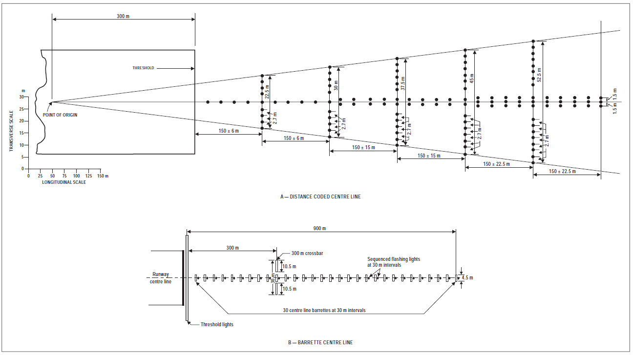 Figure M-2. Precision approach Category I lighting systems [Issue: ADR-DSN/3] [Issue: ADR-DSN/4] [Issue: ADR-DSN/5]
#### CS ADR-DSN.M.630 Precision approach Category I lighting system *ED Decision 2021/004/R* (a) The safety objective of the approach lighting system is to provide alignment and roll guidance, and limited distance-to-go information to enable safe approach to a runway. (b) Location and composition (1) General: A precision approach Category I lighting system should consist of a row of lights on the extended centre line of the runway extending wherever possible, over a distance of 900 m from the runway threshold with a row of lights forming a crossbar 30 m in length at a distance of 300 m from the runway threshold (see Figure M-2). (2) Crossbar lights: The lights forming the crossbar should be as close as practicable in a horizontal straight line at right angles to, and bisected by, the line of the centre line lights. The lights of the crossbar should be spaced so as to produce a linear effect, except that gaps may be left on each side of the centre line. These gaps should be kept to a minimum to meet local requirements and each should not exceed 6 m. (3) Centre line lights: The lights forming the centre line should be placed at longitudinal intervals of 30 m with the innermost light located 30 m from the threshold. (4) The system should lie as nearly as practicable in the horizontal plane passing through the threshold, provided that: (i) no object other than an ILS or MLS azimuth antenna should protrude through the plane of the approach lights within a distance of 60 m from the centre line of the system; and (ii) no light other than a light located within the central part of a crossbar or a centre line barrette (not their extremities) should be screened from an approaching aircraft. (iii) Any ILS or MLS azimuth antenna protruding through the plane of the lights should be treated as an obstacle and marked and lighted accordingly. (c) Characteristics: (1) The centre line and crossbar lights of a precision approach Category I lighting system should be fixed lights showing variable white. Each centre line light position should consist of either: (i) a single light source in the innermost 300 m of the centre line, two light sources in the central 300 m of the centre line, and three light sources in the outer 300 m of the centre line to provide distance information; or (ii) a barrette. (2) Where the serviceability level of the approach lights specified as a maintenance objective in [ADR.OPS.C.015](#_DxCrossRefBm1262884935) can be demonstrated, each centre line light position should consist of either: (i) a single light source; or (ii) a barrette. When barrettes are composed of lights approximating to point sources, the lights should be uniformly spaced at intervals of not more than 1.5 m. The barrettes should be at least 4 m in length. (3) If the centre line consists of lights as described in paragraph (c)(1)(i) or (c)(2)(i) above, additional crossbars of lights to the crossbar provided at 300 m from the threshold should be provided at 150 m, 450 m, 600 m and 750 m from the threshold. The lights forming each crossbar should be as nearly as practicable in a horizontal straight line at right angles to, and bisected by, the line of the centre line lights. The lights should be spaced so as to produce a linear effect, except that gaps may be left on each side of the centre line. These gaps should be kept to a minimum to meet local requirements and each should not exceed 6 m. (4) Where the additional crossbars are incorporated in the system, the outer ends of the crossbars should lie on two straight lines that either are parallel to the line of the centre line lights or converge to meet the runway centre line 300 m upwind from threshold. (5) The characteristics of lights should be in accordance with the specifications in [CS ADR-DSN.U.940](#_DxCrossRefBm1262884944), Figure U-5. The chromaticity of lights should be in accordance with the specifications in [CS ADR-DSN.U.930](#_DxCrossRefBm1262885298) and Figure U-1A or U-1B, as appropriate. (6) If the centre line consists of barrettes as described in paragraph (c)(1)(ii) or (c)(2)(ii) above, each barrette should be supplemented by a flashing light, except where such lighting is considered unnecessary taking into account the characteristics of the system, and the nature of the meteorological conditions. (7) Each flashing light, as described in paragraph (c)(6), should be flashed twice a second in sequence, beginning with the outermost light and progressing toward the threshold to the innermost light of the system. The design of the electrical circuit should be such that these lights can be operated independently of the other lights of the approach lighting system. 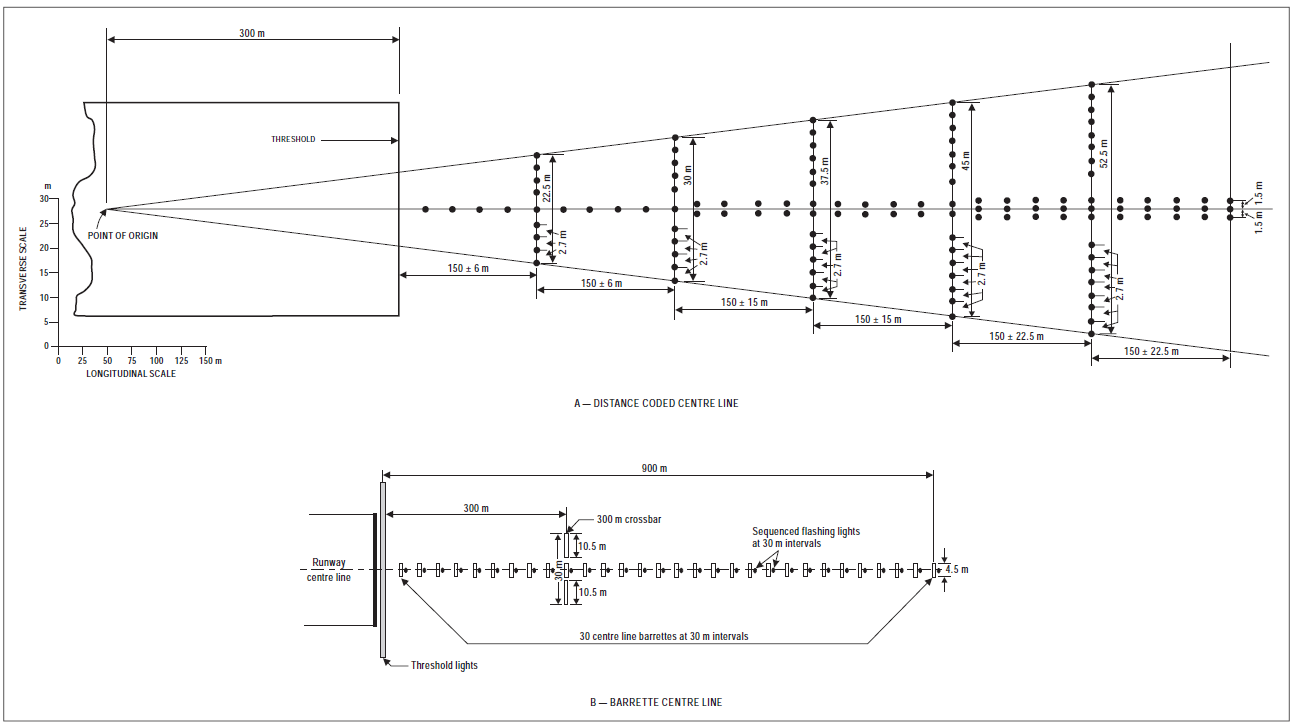 ***Figure M-2. Precision approach Category I lighting systems*** [Issue: ADR-DSN/3] [Issue: ADR-DSN/4] [Issue: ADR-DSN/5]