Light
Dark
System
Log In
Loading...
Compare / EASA/
Incorporated Amendments
/
Compare & Highlight Differences
Appendix 2.7 to ETSO-C153a - Integrated Modular Avionics (IMA) Platform and Module Minimum Performance Standard (MPS)
Available versions for ERULES-1963177438-18130
ED Decision 2020/011/R
found in: CS-ETSO Amdt 17 - European Technical Standard Orders (Oct 2026)
Version
CS-ETSO Amdt 17 - ... (Oct 2026)
Section
Share
Version
Show details
Hide details
Version
**Appendix 2.7 to ETSO-C153a – Integrated Modular Avionics (IMA) Platform and Module Minimum Performance Standard (MPS)** *ED Decision 2020/011/R* **CLASS PS: Power Supply (PS)** **1. Purpose and scope** 1.1. Introduction This Appendix contains the Minimum Performance Standard (MPS) for the CLASS PS Intended Function: Power Supply (PS). These standards specify module characteristics that should be useful to designers, manufacturers, installers and users of the module. 1.2. Definitions For ETSO-C153a CLASS PS, the IMA module is a module, mounted into a rack or the rack itself, able to supply power received from the aircraft electrical network to one or more hardware modules mounted in the same rack. The following definitions are used: — Power supply unit: a set of physical components (hardware and or software) in charge of managing a power supply (or a part of the power supply) resource. — Power supply resource: obtained electrical energy from the aircraft electrical network to be distributed to electrical loads which are modules mounted into the rack. — Power rail: a part of supplied electrical energy for which a level of isolation is guaranteed by the IMA module. — Mounted: it refers to another hardware module installed and fixed inside the IMA Rack Module after a manual operation. — Slot: a physical space inside the Rack Module allocated to one hardware module. — Hold-up Capacity: The capacity of the power supply to continue supplying output current after the input voltage drops below the minimum level. This is usually expressed as the time from the input voltage drop to the reset generated by the power supply to the processor. — Output Current Capacity: the continuously operating maximum current supplied for each output voltage. — Power Monitors & Status Outputs: a separate circuitry which checks the output voltage levels and current loading of the power supply. This circuitry will generate one or more binary signals that may be connected to the processor to alert it to the ‘out of spec’ condition. These binary signals may also force the power supply to shutdown to prevent damage to power supply components. — Power Resets: a binary signal output from the power supply that is asserted when the output voltages are outside acceptable tolerances. — Regulation: the percentage of variation of the output voltages when subjected to changes in load, changes in temperature, and changes in all input voltage transients and deviations. — Transient Immunity: the ability of the power supply to continue operating normally during variations in the input voltage. This is usually expressed as the time duration and the voltage level of the transient. — Voltage Outputs and Tolerances: the voltage levels and tolerances of the outputs produced by the power supply. In the context of PS class, the ‘concurrent item’ defined in Appendix 2.1, paragraph 1 means ‘Power Rail’. 1.3. Intended Function For ETSO-C153a CLASS PS, the intended function is to provide the capability to share the Power Supply resource supplied by one or more Power Supply unit(s). The following figure provides an overview of the above-mentioned intended function and definitions: 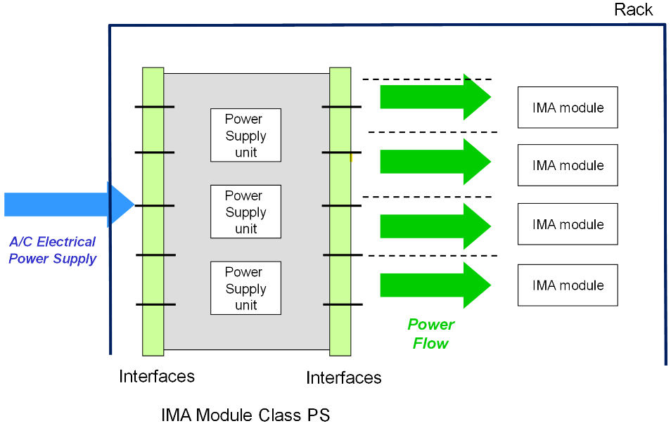 ***Figure 22: IMA module overview of ETSO-C153a CLASS PS*** **2. Requirements** 2.1. Functional requirements for ETSO-C153a CLASS PS PS.a) The IMA module shall provide to hardware modules mounted in the same rack Power Supply Resource which has the capacity to deliver a quantity of electrical energy from power supply unit(s) to the hardware modules while performing the regulation operations. PS.b) The IMA module shall provide to hardware modules mounted into the same rack the capacity to share the power supply resource thanks to power rails accessible through physical interface(s). 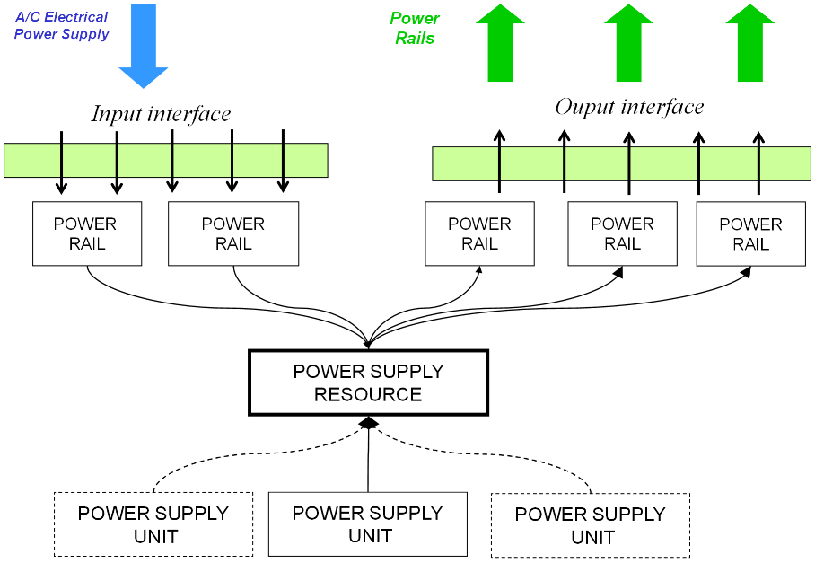 ***Figure 23: CLASS PS (PS) — the relationship between the elements*** 2.2. Characterisation requirements PS.c) All aspects of the performance of the Power Supply of the shared Power Supply Unit of the IMA module shall be characterised, including but not limited to the following: 1. The needed input power budget characteristics (e.g. as a function of temperature and load) 2. The performance of Output Currents and Tolerances; 3. The performance of Hold-up Capacity; 4. The performance of Power Monitors and Status Outputs; 5. The performance of Power Resets; 6. The performance of Power Regulation; 7. The performance of Transient Immunity; 8. The performance of Voltage Outputs and Tolerances; 9. The performance of User Interface Mechanism(s), Protocol(s) and Service(s); 10. The performance of a supported Power Rail Type; 11. The Input and Output impedance; and 12. The capacitive load. Note: These performance requirements are additional to those applicable to and dictated by the design of the IMA module itself (according to the ‘COMMON’ requirement of Appendix 2.1). PS.d) In addition to the Common Requirement 0, the characterisation shall address the safety aspects of events such as a too low voltage or current, and a too high voltage or current. The transient, as well as permanent effects, shall also be characterised, if relevant. PS.e) The characterisation shall provide any data needed to evaluate the power profile characteristics (e.g. Maximum Value, InRush Current) of managed power rails, and the IMA module power on/power off behaviour characteristics. **3. Verification procedures** The following table gives the verification method for each MPS; nevertheless, an alternative method may be proposed to the certification authority: <table bgcolor="#d9d9d9" cellpadding="7" cellspacing="0"> <col/> <col/> <col/> <col/> <col/> <tr valign="top"> <td bgcolor="#808080"><p align="center"> <b>Requirement identifier</b></p> </td> <td bgcolor="#808080"><p align="center"> <b>Verification method</b></p> </td> <td bgcolor="#808080"><p align="center"> <b>Test under normal conditions</b></p> </td> <td bgcolor="#808080"><p align="center"> <b>Test under </b> </p> <p align="center"><b>environmental conditions</b></p> </td> <td bgcolor="#808080"><p align="center"> <b>Comment</b></p> </td> </tr> <tr valign="top"> <td bgcolor="#d9d9d9"><p align="center"> <b>PS.a)</b></p> </td> <td bgcolor="#d9d9d9"><p align="center"> T</p> </td> <td bgcolor="#d9d9d9"><p align="center"> Y</p> </td> <td bgcolor="#d9d9d9"><p align="center"> Y</p> </td> <td bgcolor="#d9d9d9"><p align="center"> <br/> </p> </td> </tr> <tr valign="top"> <td bgcolor="#d9d9d9"><p align="center"> <b>PS.b)</b></p> </td> <td bgcolor="#d9d9d9"><p align="center"> T</p> </td> <td bgcolor="#d9d9d9"><p align="center"> Y</p> </td> <td bgcolor="#d9d9d9"><p align="center"> Y</p> </td> <td bgcolor="#d9d9d9"><p align="center"> <br/> </p> </td> </tr> <tr valign="top"> <td bgcolor="#d9d9d9"><p align="center"> <b>PS.c)</b></p> </td> <td bgcolor="#d9d9d9"><p align="center"> T(A*)</p> </td> <td bgcolor="#d9d9d9"><p align="center"> Y</p> </td> <td bgcolor="#d9d9d9"><p align="center"> Y<sup>(1)</sup></p> </td> <td bgcolor="#d9d9d9"><p align="center"> <br/> </p> </td> </tr> <tr valign="top"> <td bgcolor="#d9d9d9"><p align="center"> <b>PS.d)</b></p> </td> <td bgcolor="#d9d9d9"><p align="center"> T(A*)</p> </td> <td bgcolor="#d9d9d9"><p align="center"> Y</p> </td> <td bgcolor="#d9d9d9"><p align="center"> <br/> </p> </td> <td bgcolor="#d9d9d9"><p align="center"> <br/> </p> </td> </tr> <tr valign="top"> <td bgcolor="#d9d9d9"><p align="center"> <b>PS.e)</b></p> </td> <td bgcolor="#d9d9d9"><p align="center"> A</p> </td> <td bgcolor="#d9d9d9"><p align="center"> <br/> </p> </td> <td bgcolor="#d9d9d9"><p align="center"> <br/> </p> </td> <td bgcolor="#d9d9d9"><p align="center"> <br/> </p> </td> </tr> </table> ***Table 7: Verification Acceptance Criteria*** (A\*) means that verification by the Analysis method is possible for the item that cannot be tested. Note (1): applicable for a functional subset cf. CO.gg. [Amdt ETSO/10] [Amdt ETSO/16]
Contact support