Light
Dark
System
Log In
Loading...
Compare / EASA/
Incorporated Amendments
/
Compare & Highlight Differences
CS HPT-DSN.F.650 Visual alignment guidance system
Available versions for ERULES-1963177438-12355
ED Decision 2019/012/R
found in: Aerodromes (139/2014) Part-ADR.AR Part-ADR.OR Part-ADR.OPS CS-ADR-DSN CS-HPT-DSN (Dec 2024)
From
Easy Access Rules ... (Mar 2026)
Aerodromes (139/20... (Dec 2024)
Aerodromes (139/20... (Jun 2023)
From section
To
Easy Access Rules ... (Mar 2026)
Aerodromes (139/20... (Dec 2024)
Aerodromes (139/20... (Jun 2023)
To section
No visible text changes
0 removals
0 additions
View
Rich
Plain
Sync scrolling
Share
From
Show details
Hide details
To
Show details
Hide details
Version
Show side by side
CS HPT-DSN.F.650 Visual alignment guidance system ED Decision 2019/012/R (a) Applicability: Where provided at a heliport, a visual alignment guidance system should provide guidance to the pilot during the approach to a heliport. (b) Location: (1) The visual alignment guidance system should be located such that a helicopter is guided along the prescribed track towards the FATO. (2) The system should be located at the downwind edge of the FATO and aligned along the preferred approach direction. (3) The light units should be frangible and mounted as low as possible. (4) Where the lights of the system need to be seen as discrete sources, light units should be located such that at the extremes of system coverage, the angle subtended between the units as seen by the pilot should not be less than 3 minutes of arc. (5) The angles subtended between the light units of the system and other units of comparable or greater intensities should also be not less than 3 minutes of arc. (6) The requirements of paragraphs (4) and (5) above can be met for lights on a line normal to the line of sight if the light units are separated by 1 m for every kilometre of viewing range. (c) Signal format: (1) The signal format of the alignment guidance system should include a minimum of three discrete signal sectors providing ‘offset to the right’, ‘on track’ and ‘offset to the left’ signals. (2) The divergence of the ‘on track’ sector of the system should be 1° as shown in Figure F-8. (3) The signal format should be such that there is no possibility of confusion between the system and any associated visual approach slope indicator or other visual aids. (4) The system should avoid the use of the same coding as any associated visual approach slope indicator. (5) The signal format should be such that the system is unique and conspicuous in all operational environments. (6) The system should not significantly increase the pilot workload. (d) Light distribution: (1) The usable coverage of the visual alignment guidance system should be equal to or better than that of the visual approach slope indicator system with which it is associated. (2) A suitable intensity control should be provided so as to allow adjustment to meet the prevailing conditions and to avoid dazzling the pilot during approach and landing. (e) Approach track and azimuth setting: (1) A visual alignment guidance system should be capable of adjustment in azimuth to within ± 5 minutes of arc of the desired approach path. (2) The angle of the azimuth guidance system should be such that during an approach, the pilot of a helicopter at the boundary of the ‘on track’ signal would clear all objects in the approach area by a safe margin. (3) The characteristics of the obstacle protection surface specified in [CS HPT-DSN.F.660(h)(2)](#_DxCrossRefBm151831041), Table F-1 and Figure F-10 should equally apply to the system. (f) Characteristics of the visual alignment guidance system: (1) In the event of a failure of any component affecting the signal format, the system should be automatically switched off. (2) The light units should be so designed that deposits of condensation, ice, dirt, etc. on optically transmitting or reflecting surfaces would interfere to the least possible extent with the light signal and should not cause spurious or false signals to be generated. 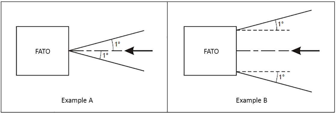 Figure F-8. Divergence of the ‘on track’ sector <table border="0" cellpadding="0" cellspacing="0"><tr><td valign="top" width="299"><p><div class="image-container"><img alt="EASA EAR image" src="/static/files/file_n2QwpTY1nQp/image177.png"/></div></p><p>Illustration 1 − Approach light steady burning</p></td><td valign="top" width="299"><p><div class="image-container"><img alt="EASA EAR image" src="/static/files/file_n2QwpTY1nQp/image178.png"/></div></p><p>Illustration 2 − Approach light flashing</p></td></tr><tr><td valign="top" width="299"><p><div class="image-container"><img alt="EASA EAR image" src="/static/files/file_n2QwpTY1nQp/image179.png"/></div></p><p>Illustration 3 − HAPI system</p></td><td valign="top" width="299"><p><div class="image-container"><img alt="EASA EAR image" src="/static/files/file_n2QwpTY1nQp/image180.png"/></div></p><p>Illustration 4 − Final approach and take-off lights and aiming point lights</p></td></tr><tr><td valign="top" width="299"><p><b><i><div class="image-container"><img alt="EASA EAR image" src="/static/files/file_n2QwpTY1nQp/image181.png"/></div></i></b></p><p>Note − Additional values may be required in the case of installations requiring identification by means of the lights at an elevation of less than two degrees.</p><p>Illustration 5 − TLOF perimeter lights and flight path alignment guidance lighting system</p></td><td valign="top" width="299"><p><b><i><div class="image-container"><img alt="EASA EAR image" src="/static/files/file_n2QwpTY1nQp/image182.png"/></div></i></b></p><p>Illustration 6 − Touchdown and lift-off area luminescent panels</p></td></tr></table> Figure F-9. Isocandela diagrams <table border="1" cellpadding="0" cellspacing="0"><tr><td valign="top" width="203"><p><b>SURFACE AND DIMENSIONS</b></p></td><td colspan="2" valign="top" width="396"><p><b>FATO</b></p></td></tr><tr><td valign="top" width="203"><p>Length of inner edge</p></td><td colspan="2" valign="top" width="396"><p>Width of safety area</p></td></tr><tr><td valign="top" width="203"><p>Distance from end of FATO</p></td><td colspan="2" valign="top" width="396"><p>3 m minimum</p></td></tr><tr><td valign="top" width="203"><p>Divergence</p></td><td colspan="2" valign="top" width="396"><p>10 %</p></td></tr><tr><td valign="top" width="203"><p>Total length</p></td><td colspan="2" valign="top" width="396"><p>2 500 m</p></td></tr><tr><td valign="top" width="203"><p>Slope</p></td><td valign="top" width="198"><p>PAPI</p></td><td valign="top" width="198"><p>A<sup>a</sup> – 0.57°</p></td></tr><tr><td valign="top" width="203"></td><td valign="top" width="198"><p>HAPI</p></td><td valign="top" width="198"><p>A<sup>b</sup> – 0.65°</p></td></tr><tr><td valign="top" width="203"></td><td valign="top" width="198"><p>APAPI</p></td><td valign="top" width="198"><p>A<sup>a</sup> – 0.9°</p></td></tr><tr><td colspan="3" valign="top" width="599"><p>a. As indicated in CS ADR-DSN.M.645, Figure M-4.</p><p>b. The angle of the upper boundary of the ‘below slope’ signal.</p></td></tr></table> Table F-1. Dimensions and slopes of the obstacle protection surface for heliport visual approach indicator system ***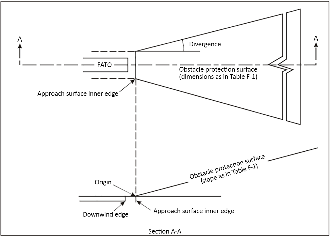*** Figure F-10. Obstacle protection surface for visual approach slope indicator systems
CS HPT-DSN.F.650 Visual alignment guidance system ED Decision 2019/012/R (a) Applicability: Where provided at a heliport, a visual alignment guidance system should provide guidance to the pilot during the approach to a heliport. (b) Location: (1) The visual alignment guidance system should be located such that a helicopter is guided along the prescribed track towards the FATO. (2) The system should be located at the downwind edge of the FATO and aligned along the preferred approach direction. (3) The light units should be frangible and mounted as low as possible. (4) Where the lights of the system need to be seen as discrete sources, light units should be located such that at the extremes of system coverage, the angle subtended between the units as seen by the pilot should not be less than 3 minutes of arc. (5) The angles subtended between the light units of the system and other units of comparable or greater intensities should also be not less than 3 minutes of arc. (6) The requirements of paragraphs (4) and (5) above can be met for lights on a line normal to the line of sight if the light units are separated by 1 m for every kilometre of viewing range. (c) Signal format: (1) The signal format of the alignment guidance system should include a minimum of three discrete signal sectors providing ‘offset to the right’, ‘on track’ and ‘offset to the left’ signals. (2) The divergence of the ‘on track’ sector of the system should be 1° as shown in Figure F-8. (3) The signal format should be such that there is no possibility of confusion between the system and any associated visual approach slope indicator or other visual aids. (4) The system should avoid the use of the same coding as any associated visual approach slope indicator. (5) The signal format should be such that the system is unique and conspicuous in all operational environments. (6) The system should not significantly increase the pilot workload. (d) Light distribution: (1) The usable coverage of the visual alignment guidance system should be equal to or better than that of the visual approach slope indicator system with which it is associated. (2) A suitable intensity control should be provided so as to allow adjustment to meet the prevailing conditions and to avoid dazzling the pilot during approach and landing. (e) Approach track and azimuth setting: (1) A visual alignment guidance system should be capable of adjustment in azimuth to within ± 5 minutes of arc of the desired approach path. (2) The angle of the azimuth guidance system should be such that during an approach, the pilot of a helicopter at the boundary of the ‘on track’ signal would clear all objects in the approach area by a safe margin. (3) The characteristics of the obstacle protection surface specified in [CS HPT-DSN.F.660(h)(2)](#_DxCrossRefBm1800047903), Table F-1 and Figure F-10 should equally apply to the system. (f) Characteristics of the visual alignment guidance system: (1) In the event of a failure of any component affecting the signal format, the system should be automatically switched off. (2) The light units should be so designed that deposits of condensation, ice, dirt, etc. on optically transmitting or reflecting surfaces would interfere to the least possible extent with the light signal and should not cause spurious or false signals to be generated. 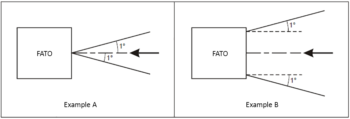 Figure F-8. Divergence of the ‘on track’ sector <table border="0" cellpadding="0" cellspacing="0"><tr><td valign="top" width="299"><p><div class="image-container"><img alt="EASA EAR image" src="/static/files/file_MR7pKKhZylO/image176.png"/></div></p><p>Illustration 1 − Approach light steady burning</p></td><td valign="top" width="299"><p><div class="image-container"><img alt="EASA EAR image" src="/static/files/file_MR7pKKhZylO/image177.png"/></div></p><p>Illustration 2 − Approach light flashing</p></td></tr><tr><td valign="top" width="299"><p><div class="image-container"><img alt="EASA EAR image" src="/static/files/file_MR7pKKhZylO/image178.png"/></div></p><p>Illustration 3 − HAPI system</p></td><td valign="top" width="299"><p><div class="image-container"><img alt="EASA EAR image" src="/static/files/file_MR7pKKhZylO/image179.png"/></div></p><p>Illustration 4 − Final approach and take-off lights and aiming point lights</p></td></tr><tr><td valign="top" width="299"><p><b><i><div class="image-container"><img alt="EASA EAR image" src="/static/files/file_MR7pKKhZylO/image180.png"/></div></i></b></p><p>Note − Additional values may be required in the case of installations requiring identification by means of the lights at an elevation of less than two degrees.</p><p>Illustration 5 − TLOF perimeter lights and flight path alignment guidance lighting system</p></td><td valign="top" width="299"><p><b><i><div class="image-container"><img alt="EASA EAR image" src="/static/files/file_MR7pKKhZylO/image181.png"/></div></i></b></p><p>Illustration 6 − Touchdown and lift-off area luminescent panels</p></td></tr></table> Figure F-9. Isocandela diagrams <table border="1" cellpadding="0" cellspacing="0"><tr><td valign="top" width="203"><p><b>SURFACE AND DIMENSIONS</b></p></td><td colspan="2" valign="top" width="396"><p><b>FATO</b></p></td></tr><tr><td valign="top" width="203"><p>Length of inner edge</p></td><td colspan="2" valign="top" width="396"><p>Width of safety area</p></td></tr><tr><td valign="top" width="203"><p>Distance from end of FATO</p></td><td colspan="2" valign="top" width="396"><p>3 m minimum</p></td></tr><tr><td valign="top" width="203"><p>Divergence</p></td><td colspan="2" valign="top" width="396"><p>10 %</p></td></tr><tr><td valign="top" width="203"><p>Total length</p></td><td colspan="2" valign="top" width="396"><p>2 500 m</p></td></tr><tr><td valign="top" width="203"><p>Slope</p></td><td valign="top" width="198"><p>PAPI</p></td><td valign="top" width="198"><p>A<sup>a</sup> – 0.57°</p></td></tr><tr><td valign="top" width="203"></td><td valign="top" width="198"><p>HAPI</p></td><td valign="top" width="198"><p>A<sup>b</sup> – 0.65°</p></td></tr><tr><td valign="top" width="203"></td><td valign="top" width="198"><p>APAPI</p></td><td valign="top" width="198"><p>A<sup>a</sup> – 0.9°</p></td></tr><tr><td colspan="3" valign="top" width="599"><p>a. As indicated in CS ADR-DSN.M.645, Figure M-4.</p><p>b. The angle of the upper boundary of the ‘below slope’ signal.</p></td></tr></table> Table F-1. Dimensions and slopes of the obstacle protection surface for heliport visual approach indicator system ***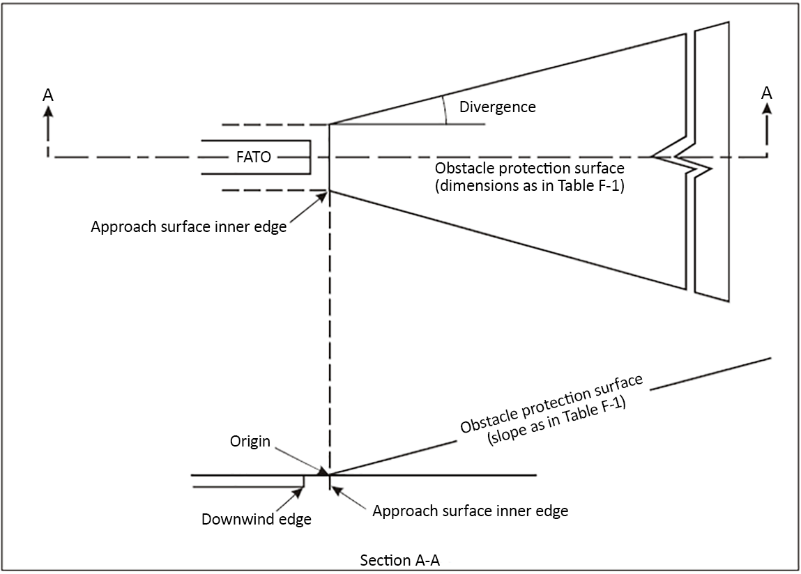*** Figure F-10. Obstacle protection surface for visual approach slope indicator systems
#### CS HPT-DSN.F.650 Visual alignment guidance system *ED Decision 2019/012/R* (a) Applicability: Where provided at a heliport, a visual alignment guidance system should provide guidance to the pilot during the approach to a heliport. (b) Location: (1) The visual alignment guidance system should be located such that a helicopter is guided along the prescribed track towards the FATO. (2) The system should be located at the downwind edge of the FATO and aligned along the preferred approach direction. (3) The light units should be frangible and mounted as low as possible. (4) Where the lights of the system need to be seen as discrete sources, light units should be located such that at the extremes of system coverage, the angle subtended between the units as seen by the pilot should not be less than 3 minutes of arc. (5) The angles subtended between the light units of the system and other units of comparable or greater intensities should also be not less than 3 minutes of arc. (6) The requirements of paragraphs (4) and (5) above can be met for lights on a line normal to the line of sight if the light units are separated by 1 m for every kilometre of viewing range. (c) Signal format: (1) The signal format of the alignment guidance system should include a minimum of three discrete signal sectors providing ‘offset to the right’, ‘on track’ and ‘offset to the left’ signals. (2) The divergence of the ‘on track’ sector of the system should be 1° as shown in Figure F-8. (3) The signal format should be such that there is no possibility of confusion between the system and any associated visual approach slope indicator or other visual aids. (4) The system should avoid the use of the same coding as any associated visual approach slope indicator. (5) The signal format should be such that the system is unique and conspicuous in all operational environments. (6) The system should not significantly increase the pilot workload. (d) Light distribution: (1) The usable coverage of the visual alignment guidance system should be equal to or better than that of the visual approach slope indicator system with which it is associated. (2) A suitable intensity control should be provided so as to allow adjustment to meet the prevailing conditions and to avoid dazzling the pilot during approach and landing. (e) Approach track and azimuth setting: (1) A visual alignment guidance system should be capable of adjustment in azimuth to within ± 5 minutes of arc of the desired approach path. (2) The angle of the azimuth guidance system should be such that during an approach, the pilot of a helicopter at the boundary of the ‘on track’ signal would clear all objects in the approach area by a safe margin. (3) The characteristics of the obstacle protection surface specified in [CS HPT-DSN.F.660(h)(2)](#_DxCrossRefBm1262885480), Table F-1 and Figure F-10 should equally apply to the system. (f) Characteristics of the visual alignment guidance system: (1) In the event of a failure of any component affecting the signal format, the system should be automatically switched off. (2) The light units should be so designed that deposits of condensation, ice, dirt, etc. on optically transmitting or reflecting surfaces would interfere to the least possible extent with the light signal and should not cause spurious or false signals to be generated. 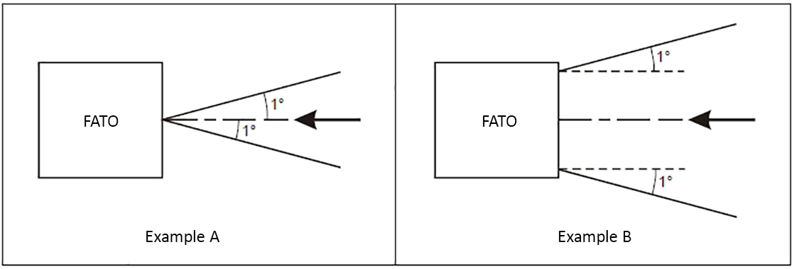 ***Figure F-8. Divergence of the ‘on track’ sector*** <table cellpadding="7" cellspacing="0"> <col/> <col/> <tr valign="top"> <td><p align="center"> <img align="bottom" border="0" name="Image66" src="source-marked.part-0002_html_bfdda6f2.png"/> </p> <p align="center"> <br/> </p> <p align="center">Illustration 1 − Approach light steady burning</p> </td> <td><p align="center"> <img align="bottom" border="0" name="Image67" src="source-marked.part-0002_html_68ab23e3.png"/> </p> <p align="center"> <br/> </p> <p align="center">Illustration 2 − Approach light flashing</p> </td> </tr> <tr valign="top"> <td><p align="center"> <img align="bottom" border="0" name="Image68" src="source-marked.part-0002_html_9963f3d1.png"/> </p> <p align="center">Illustration 3 − HAPI system</p> </td> <td><p align="center"> <img align="bottom" border="0" name="Image69" src="source-marked.part-0002_html_1869c8d0.png"/> </p> <p align="center"> <br/> </p> <p align="center">Illustration 4 − Final approach and take-off lights and aiming point lights</p> </td> </tr> <tr valign="top"> <td><p align="center"> <img align="bottom" border="0" name="Image70" src="source-marked.part-0002_html_550a0306.png"/> </p> <p align="left"> Note − Additional values may be required in the case of installations requiring identification by means of the lights at an elevation of less than two degrees.</p> <p align="center">Illustration 5 − TLOF perimeter lights and flight path alignment guidance lighting system</p> </td> <td><p align="center"> <img align="bottom" border="0" name="Image71" src="source-marked.part-0002_html_d8f2f46f.png"/> </p> <p align="center">Illustration 6 − Touchdown and lift-off area luminescent panels</p> </td> </tr> </table> ***Figure F-9. Isocandela diagrams*** <table bgcolor="#d9d9d9" cellpadding="7" cellspacing="0"> <col/> <col/> <col/> <tr valign="top"> <td bgcolor="#808080"><p align="left"> <b>SURFACE AND DIMENSIONS</b></p> </td> <td bgcolor="#808080" colspan="2"><p align="center"> <b>FATO</b></p> </td> </tr> <tr valign="top"> <td bgcolor="#d9d9d9"><p align="left"> Length of inner edge</p> </td> <td bgcolor="#d9d9d9" colspan="2"><p align="center"> Width of safety area</p> </td> </tr> <tr valign="top"> <td bgcolor="#d9d9d9"><p align="left"> Distance from end of FATO</p> </td> <td bgcolor="#d9d9d9" colspan="2"><p align="center"> 3 m minimum</p> </td> </tr> <tr valign="top"> <td bgcolor="#d9d9d9"><p align="left"> Divergence</p> </td> <td bgcolor="#d9d9d9" colspan="2"><p align="center"> 10 %</p> </td> </tr> <tr valign="top"> <td bgcolor="#d9d9d9"><p align="left"> Total length</p> </td> <td bgcolor="#d9d9d9" colspan="2"><p align="center"> 2 500 m</p> </td> </tr> <tr valign="top"> <td bgcolor="#d9d9d9"><p align="left"> Slope</p> </td> <td bgcolor="#d9d9d9"><p align="left"> PAPI</p> </td> <td bgcolor="#d9d9d9"><p align="left"> A<sup>a</sup> – 0.57°</p> </td> </tr> <tr valign="top"> <td bgcolor="#d9d9d9"><p align="left"> <br/> </p> </td> <td bgcolor="#d9d9d9"><p align="left"> HAPI</p> </td> <td bgcolor="#d9d9d9"><p align="left"> A<sup>b</sup> – 0.65°</p> </td> </tr> <tr valign="top"> <td bgcolor="#d9d9d9"><p align="left"> <br/> </p> </td> <td bgcolor="#d9d9d9"><p align="left"> APAPI</p> </td> <td bgcolor="#d9d9d9"><p align="left"> A<sup>a</sup> – 0.9°</p> </td> </tr> <tr> <td bgcolor="#d9d9d9" colspan="3" valign="top"><p align="left"> a. As indicated in CS ADR-DSN.M.645, Figure M-4.</p> <p align="left"> b. The angle of the upper boundary of the ‘below slope’ signal.</p> </td> </tr> </table> ***Table F-1. Dimensions and slopes of the obstacle protection surface for heliport visual approach indicator system*** 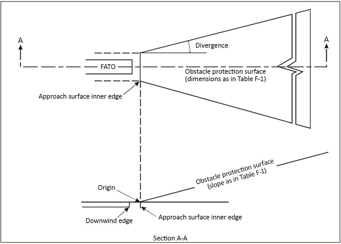 ***Figure F-10. Obstacle protection surface for visual approach slope indicator systems***