Light
Dark
System
Log In
Loading...
Compare / EASA/
Incorporated Amendments
/
Compare & Highlight Differences
CS HPT-DSN.F.620 Flight path alignment guidance marking
Available versions for ERULES-1963177438-12347
ED Decision 2019/012/R
found in: Aerodromes (139/2014) Part-ADR.AR Part-ADR.OR Part-ADR.OPS CS-ADR-DSN CS-HPT-DSN (Jun 2023)
From
Easy Access Rules ... (Mar 2026)
Aerodromes (139/20... (Dec 2024)
Aerodromes (139/20... (Jun 2023)
From section
To
Easy Access Rules ... (Mar 2026)
Aerodromes (139/20... (Dec 2024)
Aerodromes (139/20... (Jun 2023)
To section
No visible text changes
0 removals
0 additions
View
Rich
Plain
Sync scrolling
Share
From
Show details
Hide details
To
Show details
Hide details
Version
Show side by side
CS HPT-DSN.F.620 Flight path alignment guidance marking ED Decision 2019/012/R (a) Applicability: Where provided at a heliport, a flight path alignment guidance marking (or markings) should indicate the available approach and/or departure path direction(s). (b) Location: The flight path alignment guidance marking should be located in a straight line along the direction of approach and/or departure path on one or more of the TLOF, FATO, safety area or any suitable surface in the immediate vicinity of the FATO or the safety area. (c) Characteristics: (1) A flight path alignment guidance marking should consist of one or more arrows marked on the TLOF, FATO and/or safety area surface, as shown in Figure F-6. The stroke of the arrow(s) should be 50 cm in width and at least 3 m in length. When combined with a flight path alignment guidance lighting system, it should take the form shown in Figure F-6, which includes the scheme for marking the ‘heads of the arrows’, which are always of the same size, regardless of the stroke length. (2) In the case of a flight path limited to a single approach direction or a single departure direction, the arrow marking may be unidirectional. In the case of a heliport with only a single approach/departure path available, one bidirectional arrow is marked. (3) The markings should be in a colour, preferably white, which provides good contrast against the background colour of the surface on which they are marked. 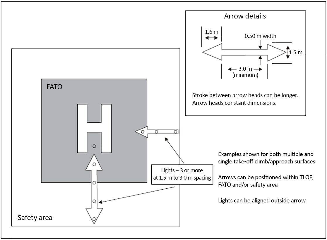 Figure F-6. Flight path alignment guidance markings and lights
CS HPT-DSN.F.620 Flight path alignment guidance marking ED Decision 2019/012/R (a) Applicability: Where provided at a heliport, a flight path alignment guidance marking (or markings) should indicate the available approach and/or departure path direction(s). (b) Location: The flight path alignment guidance marking should be located in a straight line along the direction of approach and/or departure path on one or more of the TLOF, FATO, safety area or any suitable surface in the immediate vicinity of the FATO or the safety area. (c) Characteristics: (1) A flight path alignment guidance marking should consist of one or more arrows marked on the TLOF, FATO and/or safety area surface, as shown in Figure F-6. The stroke of the arrow(s) should be 50 cm in width and at least 3 m in length. When combined with a flight path alignment guidance lighting system, it should take the form shown in Figure F-6, which includes the scheme for marking the ‘heads of the arrows’, which are always of the same size, regardless of the stroke length. (2) In the case of a flight path limited to a single approach direction or a single departure direction, the arrow marking may be unidirectional. In the case of a heliport with only a single approach/departure path available, one bidirectional arrow is marked. (3) The markings should be in a colour, preferably white, which provides good contrast against the background colour of the surface on which they are marked. 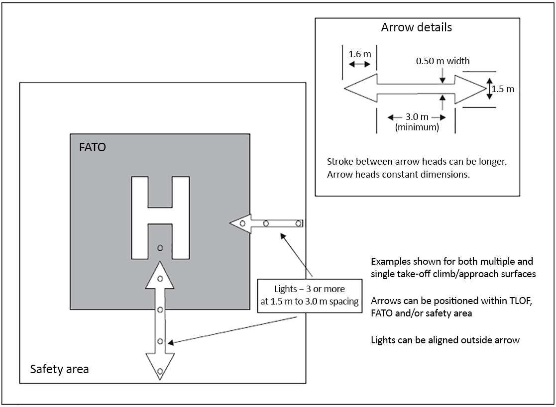 Figure F-6. Flight path alignment guidance markings and lights
#### CS HPT-DSN.F.620 Flight path alignment guidance marking *ED Decision 2019/012/R* (a) Applicability: Where provided at a heliport, a flight path alignment guidance marking (or markings) should indicate the available approach and/or departure path direction(s). (b) Location: The flight path alignment guidance marking should be located in a straight line along the direction of approach and/or departure path on one or more of the TLOF, FATO, safety area or any suitable surface in the immediate vicinity of the FATO or the safety area. (c) Characteristics: (1) A flight path alignment guidance marking should consist of one or more arrows marked on the TLOF, FATO and/or safety area surface, as shown in Figure F-6. The stroke of the arrow(s) should be 50 cm in width and at least 3 m in length. When combined with a flight path alignment guidance lighting system, it should take the form shown in Figure F-6, which includes the scheme for marking the ‘heads of the arrows’, which are always of the same size, regardless of the stroke length. (2) In the case of a flight path limited to a single approach direction or a single departure direction, the arrow marking may be unidirectional. In the case of a heliport with only a single approach/departure path available, one bidirectional arrow is marked. (3) The markings should be in a colour, preferably white, which provides good contrast against the background colour of the surface on which they are marked. 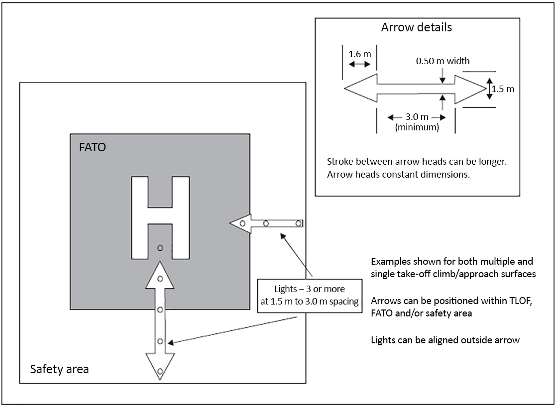 ***Figure F-6. Flight path alignment guidance markings and lights***