Light
Dark
System
Log In
Loading...
Compare / EASA/
Incorporated Amendments
/
Compare & Highlight Differences
AMC E 790(a)(2) Rain and Hail Ingestion - Turbine Engine Power/ Thrust Loss and Instability in Extreme Conditions of Rain and Hail
Available versions for ERULES-1963177438-11549
ED Decision 2018/014/R
found in: CS-E Amdt 5 - Engines (Dec 2018)
Version
...18)
Text
Removed: 0
Added: 0
Unchanged: 0
Share
AMC E 790(a)(2) Rain and Hail Ingestion – Turbine Engine Power/ Thrust Loss and Instability in Extreme Conditions of Rain and Hail ED Decision 2018/014/R (1) Definitions The following terms are defined for the purpose of this AMC: <table border="0" cellpadding="0" cellspacing="0" width="578"><tr><td valign="top" width="193"><p>Critical point(s) </p></td><td valign="top" width="384"><p>Operating conditions within the Engine flight envelope at which an Engine's operability margin is reduced to a minimum level. Operability margin includes compressor surge and stall margin, fuel control rundown margin, combustor flameout margin and instrumentation sensing errors. </p></td></tr><tr><td valign="top" width="193"><p>Flameout </p></td><td valign="top" width="384"><p>The total extinction of flame within the combustor, resulting in a rundown and, ultimately, a shutdown of the Engine. </p></td></tr><tr><td valign="top" width="193"><p>Hail </p></td><td valign="top" width="384"><p>Water in a solid granular state, either in its naturally occurring form or in a fabricated form, for the purpose of testing Engines. </p></td></tr><tr><td valign="top" width="193"><p>Hail water content (HWC)</p></td><td valign="top" width="384"><p>The concentration, in the air, of water in the form of hail, expressed in grams of hail per cubic metre of air. </p></td></tr><tr><td valign="top" width="193"><p>Rain </p></td><td valign="top" width="384"><p>Water in liquid droplet state, either in its naturally occurring form, or created artificially by discharging water from spray nozzles, for the purpose of testing Engines. </p></td></tr><tr><td valign="top" width="193"><p>Rain water content (RWC)</p></td><td valign="top" width="384"><p>The concentration, in the air, of water in the form of rain, expressed in grams of rain per cubic metre of air.</p></td></tr><tr><td valign="top" width="193"><p>Rundown</p></td><td valign="top" width="384"><p>The uncommanded reduction of Engine rotor speed that will result from the fuel control steady state operating line coinciding with the fuel control acceleration schedule.</p></td></tr><tr><td valign="top" width="193"><p>Scoop factor</p></td><td valign="top" width="384"><p>The ratio of nacelle inlet highlight area (A<sub>h</sub>) to the area of the captured air stream tube (A<sub>c</sub>) (Scoop factor = A<sub>h</sub>/A<sub>c</sub>).</p></td></tr><tr><td valign="top" width="193"><p>Stall</p></td><td valign="top" width="384"><p>An airflow breakdown at one or more compressor aerofoil stages.</p></td></tr><tr><td valign="top" width="193"><p>Surge</p></td><td valign="top" width="384"><p>The response of an entire Engine that is characterised by a significant airflow stoppage or reversal in the compression system. </p></td></tr><tr><td valign="top" width="193"><p>Sustained power or thrust loss</p></td><td valign="top" width="384"><p>A permanent reduction in power or thrust at the Engine's primary power/thrust set parameter (e.g., rotor speed, Engine pressure ratio, torque, shaft power).</p></td></tr></table> (2) Power-Loss and Instability Phenomena (a) General There have been multiple Engine power-loss and instability events, forced landings, and accidents attributed to turbine Engine malfunction in extreme conditions of rain or hail. Investigations have revealed that ambient concentrations of rain and hail can be amplified significantly through the Engine core at certain combinations of flight speed and Engine power/thrust condition. In some instances, the resulting increased amounts of ingested rain and hail have been sufficient to produce Engine anomalies such as surging, power loss and Engine flameout. (b) Meteorological Data [Appendix A](#_DxCrossRefBm1371447809) to CS-E defines the atmospheric conditions of rain and hail for the purpose of establishing certification test standards. Note that the water concentrations defined for rain and hail in [Appendix A](#_DxCrossRefBm1371447809) represent ambient conditions, not test conditions at the Engine inlet. (c) Rain and Hail Concentration Amplification and Attenuation Effects During in-flight encounters with rain and hail, changes in Engine power/thrust and flight speed can alter the rain or hail concentration within the Engine for any given atmospheric rain or hail content. (i) Scoop Factor Effect (Refer to Figure 1) The inlet capture stream tube for airflow varies widely across the spectrum of Engine power/thrust and flight speed. At low Engine power/thrust and high flight speed, the air intake specifications are minimal in comparison to the available ram air. Consequently, a significant portion of the air in front of the inlet spills outside the inlet lip (see Figure 1). Due to their mass, large rain droplets and hail are relatively unaffected by this spillage and will be captured by the inlet. The amount of rain or hail captured through the inlet will be established by the inlet highlight area. The amount of this amplification effect is equal to the ratio of the nacelle inlet highlight area (Ah) to the captured air stream tube area (Ac). This ratio is the scoop factor and it increases with decreasing Engine speed and increasing aircraft speed, due to the increase in inlet airflow spillage resulting from a smaller captured air stream tube. Further, by-pass turbofan engines may have an additional internal scoop factor effect due to the divergence of the Engine core stream tube from the nacelle inlet to the core inlet at low Engine power and high flight speed. Therefore although the scoop factor effect generally results in concentration amplification, the amplification is greatest when high flight speed is combined with low power / thrust. 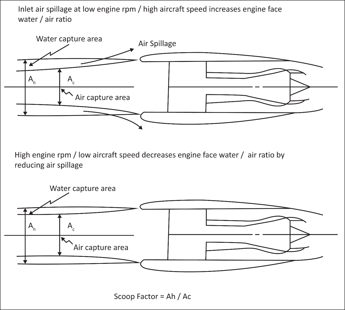 Figure 1 Scoop Factor (ii) Relative velocity centrifuging effects Some of the rain and hail will be centrifuged away from the Engine core by a fan and, to a lesser extent, away from the Engine by a Propeller. This beneficial effect is dependent upon the fan or Propeller geometry and rotational speed, inlet design and location, Engine design, aircraft velocity and on the sizes of the rain droplets and hailstones. (A) Turbofan and turbojet aeroplane Engines (Refer to Figure 2) — Rain The inlet diffusing flow field pressure gradients act to shear large droplets into small droplets that decelerate and enter the fan at velocities close to the inlet air velocity. As depicted in Figure 2, the majority of droplets that enter the Engine at gas path speeds will strike the fan and be centrifuged away from the Engine core. The forces acting upon the rain droplets in flight will vary with aeroplane velocity and altitude. A portion of the rain droplets entering the Engine may have sufficient mass such that deceleration to gas path velocity is not possible. At low Engine rotational speeds and high flight speeds, the velocity of the large rain droplets, relative to the fan, may allow that portion of the rain droplets to pass through the fan without impact (refer to hail velocity vector diagram in Figure 2) and could possibly result in higher water concentrations in the Engine core. — Hail Hail particles will maintain their size and will not be significantly affected by the Engine inlet flow field. Consequently, the hail particles will enter the Engine at close to aeroplane speed. At low Engine rotational speeds, a significant portion of the hail particles, like large rain droplets, may pass through the fan without impact (see Figure 2) and could possibly result in higher hail concentrations in the Engine core. 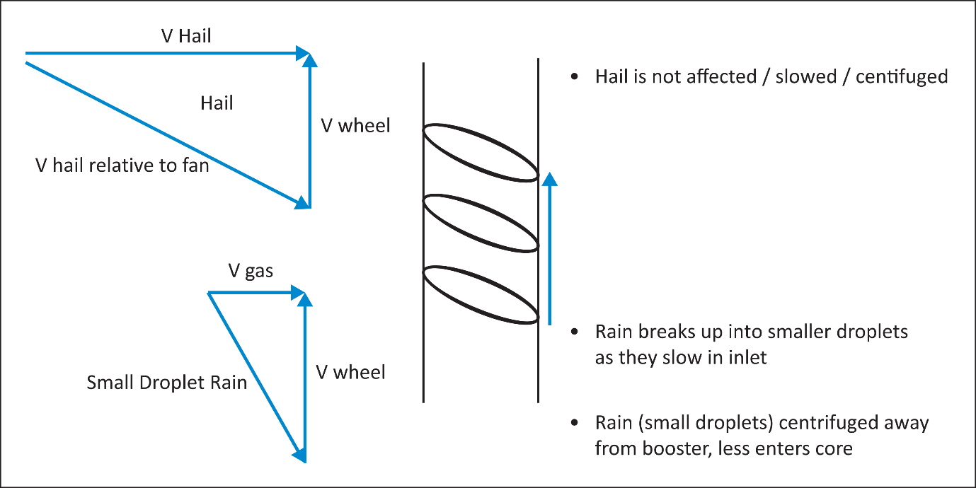 Figure 2 Velocity Vector Diagram (B) Turboprop Aeroplane Engines — Rain When compared to a turbofan Engine, the inlet flow field effect of the Propeller on droplet size and the relative velocity centrifugal effects are reduced because of the lower solidity of the Propeller. Conducting this type of test without the Propeller, either by using some other load-absorbing device or running the gas generator alone, normally results in an added degree of conservatism. Unlike turbofan Engines, the Propeller rotational speed does not vary significantly in flight, regardless of power setting. Thus, any beneficial effect of the Propeller will remain reasonably independent of altitude and power setting. Where an inlet particle separation system is incorporated, credit may be taken for its characteristics. — Hail As with rain, the effects of the Propeller on hail ingestion are generally considered beneficial by reducing the effective core concentrations so that conducting a hail test without a Propeller should result in an added degree of conservatism. Another consideration is the effect of the Propeller spinner. In a continuous hail encounter, the spinner may redirect hail into the general area of the Engine intake. The trajectory of this material will influence the effective inlet concentration and should be included in any supportive analysis for other than full-scale powerplant tests. 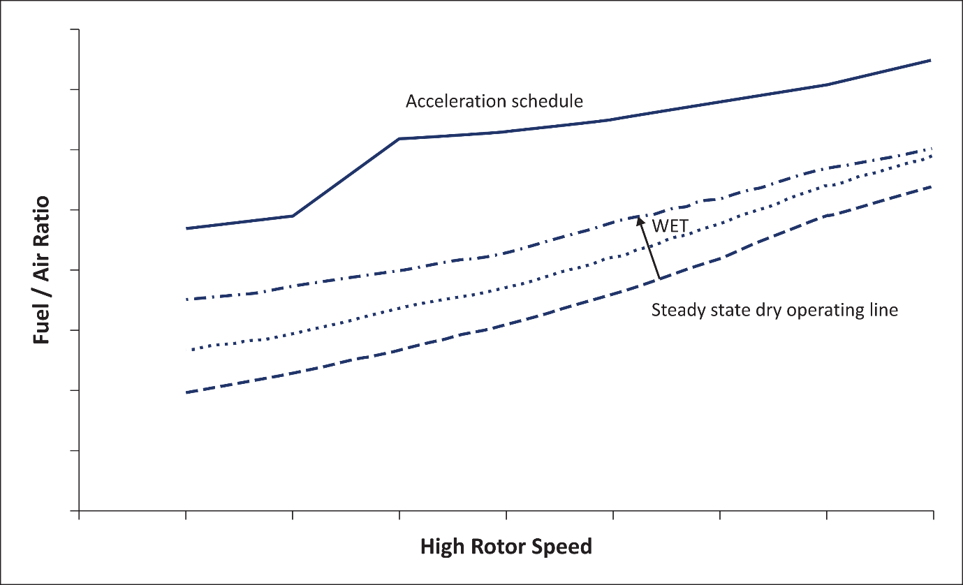 Figure 3 Typical Engine Control Characteristics (d) Rotorcraft Turbine Engines For rotorcraft applications, testing to the specifications of [CS-E 790(a)(2)](#_DxCrossRefBm1371447599) may be replaced by the static rain ingestion test specified in [CS-E 790(b)](#_DxCrossRefBm1371447599). While it may be possible to define in-flight rain and hail concentration amplification and attenuation effects for rotorcraft installations similar to aeroplane installations, these effects are typically small. When compared to aeroplanes, the proportionately higher Engine power during descent and the lower flight speeds of rotorcraft result in a small scoop factor effect. Rotorcraft turbine engines might not have rotating components that centrifuge rain or hail away from the Engine. While differences in centrifuging capability between static test conditions and flight operation is an important consideration for turbofan engines, it typically has no applicability to rotorcraft turbine engines. Increasing the ambient rain concentration from [Appendix A](#_DxCrossRefBm1371447809) values to 4 percent water droplet flow to airflow, by weight, will usually compensate for any flight effects. (e) Turbine Engine Operability Effects As stated previously, rain and hail ingested into a turbine Engine can be at greater than ambient concentrations in the Engine at certain combinations of flight speed and Engine power/thrust condition. Ingestion of rain or hail through the Engine core can produce a number of Engine operational anomalies including compressor surge, power/thrust loss and flameout. These operational anomalies are partly a result of the changes in the thermodynamic cycle of the turbine Engine because of the presence of water as a result of ingesting rain or hail. (i) Compressor rematch The presence of rain or hail particles or water from melted hail in the gas path causes the compressor to assume new operating conditions. The net overall effect may result in an increase in compressor operating line, with a corresponding decrease in compressor surge and stall margins. (ii) Engine control response (Refer to Figure 3) The fuel control steady state operating line will move upward toward the acceleration schedule as the amount of ingested rain or hail increases (see Figure 3). A higher operating line means that more fuel is required to sustain steady-state operation. When the operating line coincides with the acceleration schedule, the fuel control may be unable to deliver additional fuel to accommodate the increasing rain or hail ingestion. Under this condition, the Engine may rundown and could result in sub-idle Engine operation, a loss of throttle response, or flameout. (iii) Combustor response The evaporation, in the combustor, of the liquid water resulting from the ingestion of rain or hail will cause a reduction in combustor flame temperature and will adversely affect combustor performance. The reduced temperature will result in slowing of the chemical reaction rate and inhibit complete combustion. This results in reductions in combustor efficiency and stability. Typically, the combustor is most susceptible to flameout when it is required to operate at a sub-idle operating condition. Therefore, a flameout condition may be preceded by Engine rundown as discussed previously in paragraph (2)(e)(ii) of this AMC. (f) Case Contraction As rain or hail is ingested into any turbine Engine, the temperature of the compressor case may decrease at a faster rate than the compressor rotor. This would result in a reduction in compressor blade tip clearances and may result in blade tip rubs. Turbine Engine types, such as turbojets, that have a significant scoop factor effect but lack design features to direct rain or hail away from the Engine core (e.g. fan blades, bypass splitter, etc.) may be more susceptible to damage resulting from case contraction. (3) Design Factors (a) General The response of a turbine Engine to a rain or hail encounter depends on a number of design and operational factors. The manufacturer can greatly improve the operability of the Engine during an extreme rain or hail encounter by incorporating certain design features. However, there may be a trade-off with some of these design features. For instance, a spinner designed to maximise hail rebound and rain droplet centrifuging may also result in a spinner which is more susceptible to large ice accretions. (b) Design Features With knowledge of the power-loss and instability phenomena, the applicant can incorporate design features that increase the Engine's tolerance to rain and hail ingestion. (i) Fan blade or Propeller design and operating speeds. The fan blade or Propeller, under the right conditions, can effectively centrifuge small droplets of rain away from the Engine core. Hail particles and large droplets of rain can also be moved away from the Engine core by the fan blade or Propeller, but with considerably less effectiveness. The applicant should consider the relative velocity effects at the critical points when establishing fan blade or Propeller geometry and operating speeds. (ii) Spinner or nose cone A spinner or nose cone can effectively deflect rain and hail away from the Engine core. Designing the spinner or nose cone to maximise hail deflection requires knowledge of the post impact trajectory characteristics of hail particles. (iii) Bypass splitter In the case of turbofan Engines, increasing the gap between the fan blades' trailing edges and the bypass splitter will normally tend to enhance the benefits, to the Engine core, of the centrifugal effects of the fan blades. (iv) Engine air bleeds Engine air bleeds ports provide a direct means of redirecting or extracting rain and hail away from the Engine core and a direct means of improving compressor surge and stall margins. The effectiveness of the bleed port in extracting liquid water or hail particles out of the Engine core will depend on the radial distribution of the water or hail particles, the location and the entrance geometry of the bleed port and the bleed control logic. Also, in the case of hail, the bleed port should be designed to minimise the likelihood of clogging and blockage. (v) Engine and aircraft accessory loads Accessory loads will tend to move the fuel control operating line closer to the acceleration schedule and, therefore, should be minimised, where possible, while in rain and hail conditions. (vi) Fuel control Fuel controls that schedule fuel using a rate change of compressor speed should provide consistent acceleration and deceleration thrust response during rain or hail ingestion. (vii) Variable stator vane The schedule of the compressor variable stator vanes directly affects the compressor performance, operability and stability characteristics. Weather-related sensing or scheduling errors may cause a loss of surge or stall margin. (c) Operational Factors With knowledge of the power-loss and instability phenomena, the applicant can establish an operating envelope which minimises the power-loss and instability threats. (i) Increased power/thrust levels Increasing Engine power/thrust will increase rotor speeds and air intake specifications. This is beneficial because an increase in rotor speed will tend to improve centrifuging, while an increase in airflow will tend to decrease the adverse scoop factor effect. Combustor stability margin will also be improved with increased power / thrust. (ii) Avoidance of Engine transients Avoidance of Engine transients improves the stall and surge tolerance of the Engine and reduces the likelihood of rundown. However, avoidance of throttle transients should not be used by the applicant to show compliance with the rain and hail ingestion specifications. (iii) Decreased flight speeds Reduced aircraft speed, like increased power levels, is beneficial because it improves centrifuging while decreasing the adverse scoop factor effect. (4) Critical Point Analysis (a) General Compliance with the specifications of [CS-E 790(a)(2)](#_DxCrossRefBm1371447599) is a two-step procedure. The first step is to identify, through analysis, the critical operating points for rain and hail ingestion. The second step is to test the Engine at selected critical points to validate the Engine's capability to adequately withstand extreme rain and hail encounters. The applicant should develop a critical point analysis and submit the analysis to the Agency for concurrence, prior to the rain and hail ingestion testing. (b) Critical Point Analysis Elements The purpose of the critical point analysis is to identify operating points within the Engine flight envelope where operability margins are minimised due to the ingestion of rain or hail. The analysis should encompass the full range of all pertinent variables. These variable include, but are not limited to: (i) Atmospheric conditions The rain and hail threats identified in Figure A1 and Tables A1 to A4 in [Appendix A](#_DxCrossRefBm1371447809) of CS-E should be used for this purpose. The critical point analysis should consider the effects of nominal, as well as extreme, levels of rain or hail on the function of all relevant Engine components and systems. (ii) Rain and hail concentration amplification and attenuation effects The critical point analysis should quantify the amount of rain and, separately, the amount of hail ingested into the Engine core. Therefore, amplification and attenuation effects, such as the scoop factor effect and the relative velocity effect, should be quantified. This may necessitate assessing a representative installation aerodynamic flow field and probable flight profiles. In the case of rain ingestion, droplet break-up characteristics need to be established or conservatively assessed. In the case of hail ingestion, the trajectories of hail particles after impacting nose cones, spinners, inlet surfaces, blades and vanes, etc. need to be established or conservatively assessed for determining critical points. (iii) Engine power level The entire envelope of power/thrust conditions should be analysed. While rundown and flameout are predominantly low power/thrust anomalies, compressor stability problems could occur at high power/thrust. (iv) Engine parasitics The variability of Engine parasitics, such as air bleeds and accessory loads, should be analysed for their effect on the critical points. (c) Critical Point Analysis Procedure The critical point analysis is an assessment of the Engine's capability throughout its operating envelope, given the range of event variables described above and any Engine operability condition which is affected by ingested rain or hail. Typical operability conditions to consider include surge and stall margin, fuel control rundown margin, combustor flameout margin and instrumentation sensing errors. The critical point analysis should also address case contraction. (5) Compliance Methods (a) General An Engine compliance test method consistent with the critical point analysis may include the use of a ground-level static facility with appropriate means of conducting Engine tests with the ingestion of simulated rain and hail at the increased concentrations that are necessary to produce in-flight effects on the concentrations of ingested rain and hail and to compensate for the differences between the critical point conditions and the ground-level test conditions. Other possibilities for demonstrating compliance include wind tunnel testing, direct core water-injection tests, component rig tests, scale model tests, and analyses. (b) Test Point Selection The critical hail point(s) and rain point(s) that yield the least operability margin should be demonstrated by Engine ingestion testing. Additional test points should be considered if any of the operability margins are determined to be minimal (i.e. compressor surge and stall, combustor blow-out, fuel control rundown, instrumentation sensing errors, etc.). (c) Critical Point Testing At Ground Level The applicant may test the Engine at ground-level conditions, provided the relevant Engine operational factors of the critical points are reproduced in a meaningful relationship. (i) Test Compensation The applicant should compensate for differences between the critical point conditions and the test facility conditions. These differences may include: (A) Air density The critical point percentage of rain and hail concentration by weight should be reproduced during the test. For example, 20 g/m3 of rain at 20 000 feet is approximately 3 per cent water by weight. At sea level this percentage of water requires nearly 40 g/m3 to compensate for the higher air density (refer to Figure A1 in [Appendix A](#_DxCrossRefBm1371447809) of CS-E). (B) Atmospheric parameters In respect of air temperature and other atmospheric parameters, the appropriate ISA data may be assumed when adjusting concentrations of rain and hail. (C) Scoop factor The appropriate rain and hail concentration amplification due to the scoop factor effect should be applied to further increase the quantities of rain and hail for the ground-level tests. This necessitates having knowledge of the inlet diffusing flow field throughout the Engine Power/Thrust range and flight envelope. (D) Engine rotational speeds The low rotor speed for the ground-level test should be no greater than the altitude critical point condition. This is particularly important for turbofan Engines since the rotational speed determines the rain and hail centrifuging effects which prevent some of the rain and hail from reaching the Engine core. The rain and hail concentrations may be adjusted to compensate for any necessary deviation from critical point rotational speeds. (E) Variable systems All variable systems, such as Engine bleeds, whose position can affect the Engine operation in rain and hail, should be set in the position associated with the critical point. (F) Engine power extraction It should be shown by analysis or test that sufficient margin exists for the extraction of the representative electrical or shaft power loads and service air bleeds. (G) Thermodynamic cycle differences There may be thermodynamic cycle differences between the test point and the critical point which affect the operability of the Engine. There should be compensation for these cycle differences, or it should be shown that these differences provide additional conservatism. (H) Enthalpy of water Rain and hail concentrations may be adjusted to ensure that the heat extraction resulting from their ingestion is the same as the critical point. If the ingestion of liquid water droplets is accepted (see paragraph 5(d) for compliance alternatives) for critical hail point testing, then the water concentration should at least be increased to compensate for the heat of fusion of ice. (I) Rain droplet break-up In the ground-level test environment, forces applied to accelerate the simulated rain droplets to flight speed, as well as shear forces between the droplets and the Engine airflow, are apt to break up the droplets. This break-up can result in reduced conservatism due to additional centrifuging by the fan or Propeller and spinner. The concentration of the rain may need to be increased to compensate for the added centrifuging resulting from ground-level testing. (ii) Engine test facility The Engine test facility should provide a uniform water droplet or hail spatial distribution within the critical area of a plane within the Engine intake, and that plane should be agreed to by the Agency. The facility should also provide proper droplet or particle sizes and proper velocity distributions, unless otherwise justified in accordance with [Appendix A](#_DxCrossRefBm1371447809) to CS-E. (iii) Instrumentation Instrumentation and data sampling rates should be sufficient to establish the rain and hail temperatures and concentrations, particle velocities and size distributions, and the Engine response. Primary exhaust water-to-air ratio measurements via gas sampling should be considered. Instrumentation accuracy and repeatability should be demonstrated by suitable means. (iv) Test procedure The test procedure should consider the following for operability critical point tests and for the thermal shock (rain only) critical point test: (A) Stabilise the Engine at the critical point conditions. (B) Take steady-state data readings before introducing rain or hail. (C) Start the continuous transient data recording prior to the initiation of rain or hail flow. (D) Establish the altitude equivalent rain or hail flow at the proper inlet velocity and size distribution. The maximum rain and hail ingestion rates should occur within 10 seconds. (E) Conduct operability critical point tests at the following steady-state conditions: (a) Deliver rain for a minimum of 3 minutes, at the altitude equivalent concentration defined in Figure A1 and Table A1 in [Appendix A](#_DxCrossRefBm1371447809) of CS-E. (b) Deliver hail for a minimum of 30 seconds, at the altitude equivalent concentration defined in Figure A1 and Table A2 in [Appendix A](#_DxCrossRefBm1371447809) of CS-E. (c) Deliver a short burst of high-concentration hail of 13 g/m3 hail water content (HWC) under conditions representative of a 15 000-ft altitude for a minimum of 5 seconds. Note: Applicants can elect to integrate the test point required by paragraph (E)(c) within the 30-Second test point required by paragraph (E)(b), or consider it separately using test or analysis. Applicants may also propose justifiable alternatives to assess similar short-term, high-concentration threats. (F) When testing low-power critical points (i.e. the minimum flameout and/or rundown margin), conduct tests with ingestion during the following transient operating conditions: (α) accelerate the Engine with a 1-Second throttle movement to the rated Take-off Power or Thrust from the minimum rotor speed defined by the critical point analysis; and (β) stabilise the Engine at 50% of the rated Take-off Power or Thrust with ingestion, then, with a 1-Second throttle movement, decelerate to the minimum rotor speed defined by the critical point analysis; or (γ) if test conditions or test facility limitations prevent transient testing as defined in (α) and (β) above, the applicant may propose alternative test criteria, provided that such alternative test criteria (and any complementary substantiation) validates that the Engine has sufficient operability margins to account for likely flight operations such as missed approaches (i.e., go-around) and likely throttle movements during descent. (G) Conduct the thermal shock critical point test by delivering rain for 3 minutes at the critical Power/Thrust condition following a normal stabilisation period without water ingestion. The maximum rain ingestion rate should occur within 10 seconds. (v) Probable factors It should be demonstrated by test or analysis, that the Engine tested in accordance with paragraph (5)(c)(iv) of this AMC would have operated acceptably if it was exposed to other probable factors associated with a rain or hail encounter. These other probable factors would include, but are not limited to, typical Engine performance losses, installation effects, and typical autothrottle power excursions. (vi) Acceptance criteria Acceptable Engine operation precludes flameout, rundown, continued or non- recoverable surge or stall, or a loss of acceleration and deceleration capability. A momentary flameout, surge or stall that arrests itself without operational intervention (e.g. without throttle manipulation) is acceptable. If, after test, it is found that damage has occurred, further running or other evidence may be required to show that subsequent Failures resulting from the damage are unlikely to occur before the damage is rectified. Engine performance should be measured before and after the rain and hail ingestion tests to assess steady-state performance changes. Data should be normalised according to the applicant's standard practices and the evaluation of sustained loss or degradation of power or thrust should encompass the full range of Engine power or thrust. If compliance with these criteria is dependent upon the functioning of an automatic protection system, such as continuous ignition, auto-relight, surge recovery system, then the availability of this system is considered to be critical for dispatch. (A) Sustained power or thrust loss The sustained power or thrust loss as a result of a shift or error in measured thrust or power against the primary thrust or power set parameter(s) following the ingestion test, should be limited to 3 percent. Measured post-ingestion power or thrust losses greater than 3 per cent at any value of the primary setting parameter, can only be accepted when supported by appropriate assessments of aircraft performance. (B) Power or thrust degradation A change in the Engine corrected thrust or power of up to 10 per cent from rated or pre-test levels when using the applicant's normal performance parameters (i.e., Exhaust Gas Temperature, High Rotor Speed, etc.), excluding the primary thrust or power setting parameter, is acceptable provided the criterion for sustained power or thrust loss is met. Note: Due to the adjustment of the hail water content (HWC) to account for the higher air density at sea level compared with the altitude flight conditions required by paragraph (5)(c)(i)(A) of this AMC, it is possible that the pressure altitude density effect on the HWC may result in ice accretion within the Engine that would not occur in flight. The amount of ice accretion within the Engine compressor will depend on the absolute HWC level, rather than the water-to-air ratio within the Engine. If an issue with ice accretion is revealed during the testing required by paragraph (5)(c)(iv) of this AMC with amplified HWC, the applicant may need to repeat the testing at the levels identified in Appendix A to CS-E to evaluate the true ice accretion threat. Alternatively, the applicant may elect to run an initial test at those levels identified in Appendix A to CS-E to demonstrate the capability of the Engine with respect to ice accretion before performing the operability test with a higher HWC. Irrespective of the effects of pressure altitude density, flight airspeed effects should still be applied to the Engine test simulation. (d) Other Compliance Alternatives Analysis may be used in lieu of, or in combination with, Engine testing to demonstrate compliance with the specifications. The analytical methods used should have a sufficient validation basis to justify the accuracy of the predictions or be shown to yield conservative results. The amount of validation (i.e. Engine test, rig test, experimental test, etc.) should be proportional to the complexity of the analytical methods used and to the criticality of the particular calculation to the prediction of Engine operability. [Amdt No: E/1] [Amdt No: E/5]