Light
Dark
System
Log In
Loading...
Compare / EASA/
Incorporated Amendments
/
Compare & Highlight Differences
AMC2 27.801(e) and 27.802(c) Model test method for flotation stability
Available versions for ERULES-1963177438-11504
ED Decision 2018/007/R
found in: CS-27 Amdt 9 - Small Rotorcraft (Dec 2021)
ED Decision 2023/001/R
found in: CS-27 Amdt 10 - Small Rotorcraft (Feb 2023)
From
CS-27 Amdt 10 - Sm... (Feb 2023)
CS-27 Amdt 9 - Sma... (Dec 2021)
From section
To
CS-27 Amdt 10 - Sm... (Feb 2023)
CS-27 Amdt 9 - Sma... (Dec 2021)
To section
No visible text changes
0 removals
0 additions
View
Rich
Plain
Sync scrolling
Share
From
Show details
Hide details
To
Show details
Hide details
Version
Show side by side
AMC to CS 27.801(e) and 27.802(c) Model test method for flotation stability ED Decision 2018/007/R This AMC should be used when showing compliance with [CS 27.801(e)](#_DxCrossRefBm472493312) or [CS 27.802(c)](#_DxCrossRefBm472493311) as introduced at Amendment 5. (a) Explanation (1) Model test objectives The objective of the model tests described in the certification specification is to establish the performance of the rotorcraft in terms of its stability in waves. The wave conditions in which the rotorcraft is to be certified should be selected according to the desired level of operability (see (a)(2) below). This will enable the overall performance of the rotorcraft to be established for inclusion in the rotorcraft flight manual (RFM) as required by [CS 27.1587(b)(3)](#_DxCrossRefBm472493391). In the case of approval with ditching provisions, the wave conditions selected for substantiation of behaviour during the water entry phase must also be taken into account. The rotorcraft design is to be tested, at each mass condition (see paragraph b(1)(ii) below), with its flotation system intact, and with its single most critical flotation compartment damaged (i.e. the single-puncture case which has the worst adverse effect on flotation stability). (2) Model test wave conditions The rotorcraft is to be tested in a single sea condition comprising a single combination of significant wave height (Hs) and zero-crossing period (Tz). The values of Hs and Tz should be no less than, and no more than, respectively, those chosen for certification, i.e. as selected from table 1. This approach is necessary in order to constrain the quantity of testing required within reasonable limits and is considered to be conservative. The justification is detailed in [Appendix 2](#_DxCrossRefBm472493389). The applicant is at liberty to certify the rotorcraft to any significant wave height Hs. This significant wave height will be noted as performance information in the RFM. Using reliable wave climate data for an appropriate region of the ocean for the anticipated flight operations, a Tz is selected to accompany the Hs. This Tz should be typical of those occurring at Hs as determined in the wave scatter table for the region. The mode or median of the Tz distribution at Hs should be used. It is considered that the northern North Sea represents a conservatively ‘hostile’ region of the ocean worldwide and should be adopted as the default wave climate for certification. However, this does not preclude an applicant from certifying a rotorcraft specifically for a different region. Such a certification for a specific region would require the geographical limits of that certification region to be noted as performance information in the RFM. Certification for the default northern North Sea wave climate does not require any geographical limits. In the case of an approval with emergency flotation provisions, operational limitations may limit flight to ‘non-hostile’ sea areas. For simplicity, the northern North Sea may still be selected as the wave climate for certification, or alternatively a wave climate derived from a non-hostile region’s data may be used. If the latter approach is chosen, and it is desired to avoid geographical limits, a ‘non-hostile’ default wave climate will need to be agreed with EASA. Wave climate data for the northern North Sea were obtained from the United Kingdom Meteorological Office (UK Met Office) for a typical ‘hostile’ helicopter route. The route selected was from Aberdeen to Block 211/27 in the UK sector of the North Sea. Data tables were derived from a UK Met Office analysis of 34 years of 3-hourly wave data generated within an 8-km, resolved wave model hindcast for European waters. This data represents the default wave climate. Table 1 below has been derived from this data and contains combinations of Hs and Tz. Table 1 also includes the probability of exceedance (Pe) of the Hs. Table 1 — Northern North Sea wave climate <table border="1" cellpadding="0" cellspacing="0" width="607"><thead><tr><td valign="top" width="35"><p></p></td><td colspan="4" valign="top" width="572"><p><b>Spectrum shape: JONSWAP, peak enhancement factor γ = 3.3</b></p></td></tr><tr><td valign="top" width="35"><p></p></td><td valign="top" width="143"><p><b>Significant wave height <i>Hs</i></b></p></td><td valign="top" width="143"><p><b>Mean wave period <i>Tz</i></b></p></td><td valign="top" width="143"><p><b>Significant steepness</b></p><p><b><i>Ss = 2πHs/(gTz2)</i></b></p></td><td valign="top" width="143"><p><b>Hs probability of exceedance <i>Pe</i></b></p></td></tr></thead><tr><td rowspan="10" valign="top" width="35"><p><b>Intact flotation system</b></p></td><td valign="top" width="143"><p>6 m </p></td><td valign="top" width="143"><p>7.9 s </p></td><td valign="top" width="143"><p>1/16.2 </p></td><td valign="top" width="143"><p>1.2 % </p></td></tr><tr><td valign="top" width="143"><p>5.5 m </p></td><td valign="top" width="143"><p>7.6 s </p></td><td valign="top" width="143"><p>1/16.4 </p></td><td valign="top" width="143"><p>2 % </p></td></tr><tr><td valign="top" width="143"><p>5 m </p></td><td valign="top" width="143"><p>7.3 s </p></td><td valign="top" width="143"><p>1/16.6 </p></td><td valign="top" width="143"><p>3 % </p></td></tr><tr><td valign="top" width="143"><p>4.5 m </p></td><td valign="top" width="143"><p>7.0 s </p></td><td valign="top" width="143"><p>1/17.0 </p></td><td valign="top" width="143"><p>5 % </p></td></tr><tr><td valign="top" width="143"><p>4 m </p></td><td valign="top" width="143"><p>6.7 s </p></td><td valign="top" width="143"><p>1/17.5 </p></td><td valign="top" width="143"><p>8 % </p></td></tr><tr><td valign="top" width="143"><p>3.5 m </p></td><td valign="top" width="143"><p>6.3 s </p></td><td valign="top" width="143"><p>1/17.7 </p></td><td valign="top" width="143"><p>13 % </p></td></tr><tr><td valign="top" width="143"><p>3 m </p></td><td valign="top" width="143"><p>5.9 s </p></td><td valign="top" width="143"><p>1/18.1 </p></td><td valign="top" width="143"><p>20 % </p></td></tr><tr><td valign="top" width="143"><p>2.5 m </p></td><td valign="top" width="143"><p>5.5 s </p></td><td valign="top" width="143"><p>1/18.9 </p></td><td valign="top" width="143"><p>29 % </p></td></tr><tr><td valign="top" width="143"><p>2 m </p></td><td valign="top" width="143"><p>5.1 s </p></td><td valign="top" width="143"><p>1/20.3 </p></td><td valign="top" width="143"><p>43 % </p></td></tr><tr><td valign="top" width="143"><p>1.25 m </p></td><td valign="top" width="143"><p>4.4 s </p></td><td valign="top" width="143"><p>1/24.2 </p></td><td valign="top" width="143"><p>72 % </p></td></tr></table> (3) Target probability of capsizing Target probabilities of capsizing have been derived from a risk assessment. The target probabilities to be applied are as stated in [CS 27.801(e)](#_DxCrossRefBm472493312) and [27.802(c)](#_DxCrossRefBm472493311), as applicable. For ditching, the intact flotation system probability of capsizing of 3 % is derived from a historic ditching rate of 3.32 x 10⁻⁶ per flight hour and an AMC 27.1309 consequence of hazardous, which implies a frequency of capsizing of less than 10-7 per flight hour. The damaged flotation system probability of capsizing is increased by a factor of 10 to 30 % on the assumption that the probability of failure of the critical float compartment is 0.1; this probability has been estimated, as there is insufficient data on flotation system failure rates. For emergency flotation equipment, an increase of half an order (√10) is allowed on the assumption of a reduced exposure to the risk, resulting in a probability of capsizing of 10 %. The probability of a capsizing with a damaged flotation system is consequently increased to 100 %, hence no test is required. (4) Intact flotation system For the case of an intact flotation system, if the northern North Sea default wave climate has been chosen for certification, the rotorcraft should be shown to resist capsize in a sea condition selected from Table 1. The probability of capsizing in a 5-minute exposure to the selected sea condition is to be demonstrated to be less than or equal to the appropriate value provided in [CS 27.801(e)](#_DxCrossRefBm472493312) or [27.802(c)](#_DxCrossRefBm472493311), as appropriate, with a confidence of 95 % or greater. (5) Damaged flotation system For the case of a damaged flotation compartment (see (1) above), the same sea condition may be used, but a 10-fold increased probability of capsizing is permitted. This is because it is assumed that flotation system damage will occur in approximately one out of ten emergency landings on water. Thus, the probability of capsizing in a 5-minute exposure to the sea condition is to be demonstrated to be less than or equal to 10 times the required probability for the intact flotation system case, with a confidence of 95 % or greater. Where a 10-times probability is equal to or greater than 100 %, it is not necessary to perform a model test to determine the capsize probability with a damaged flotation system. Alternatively, the applicant may select a wave condition with 10 times the probability of exceedance Pe of the significant wave height (Hs) selected for the intact flotation condition. In this case, the probability of capsizing in a 5-minute exposure to the sea condition is to be demonstrated to be less than or equal to the required value (see [CS 27.801(e)](#_DxCrossRefBm472493312) or [27.802(c)](#_DxCrossRefBm472493311)), with a confidence of 95 % or greater. (6) Long-crested waves Whilst it is recognised that ocean waves are in general multidirectional (short-crested), the model tests are to be performed in unidirectional (long-crested) waves, this being regarded as a conservative approach to capsize probability. (b) Procedures (1) Rotorcraft model (i) Construction and scale of the model The rotorcraft model, including its emergency flotation, is to be constructed to be geometrically similar to the full-scale rotorcraft design at a scale that will permit the required wave conditions to be accurately represented in the model basin. It is recommended that the scale of the model should be not smaller than 1/15. The construction of the model is to be sufficiently light to permit the model to be ballasted to achieve the desired weight and rotational inertias specified in the mass conditions (see (b)(1)(ii) below)[[3]](#_ftn3). Where it is likely that water may flood into the internal spaces following an emergency landing on water, for example through doors opened to permit escape, or any other opening, the model should represent these internal spaces and openings as realistically as possible. It is permissible to omit the main rotor(s) from the model, but its (their) mass is to be represented in the mass and inertia conditions[[4]](#_ftn4). (ii) Mass conditions As it is unlikely that the most critical condition can be determined reliably prior to testing, the model is to be tested in two mass conditions: (A) maximum mass condition, mid C of G; and (B) minimum mass condition, mid C of G. (iii) Mass properties The model is to be ballasted in order to achieve the required scale weight, centre of gravity, roll and yaw inertia for each of the mass conditions to be tested. Once ballasted, the model’s floating draft and trim in calm water is to be checked and compared with the design floating attitude. The required mass properties and floating draft and trim, and those measured during model preparation, are to be fully documented and compared in the report. (iv) Model restraint system The primary method of testing is with a restrained model, but an alternative option is for a free-floating model (See (3)(iii) below). For the primary restrained method, a flexible restraint or mooring system is to be provided to restrain the model in order for it to remain beam-on to the waves in the model basin[[5]](#_ftn5). This restraint system should fulfil the following criteria: (A) be attached to the model on the centre line at the front and rear of the fuselage in such a position that roll motion coupling is minimised; an attachment at or near the waterline is preferred; and (B) be sufficiently flexible that the natural frequencies of the model surging/swaying on this restraint system are much lower than the lowest wave frequencies in the spectrum. (v) Sea anchor Whether or not the rotorcraft is to be fitted with a sea anchor, such an anchor is not to be represented in these model tests[[6]](#_ftn6). (2) Test facility The model test facility is to have the capability to generate realistic long non-repeating sequences of unidirectional (long-crested) irregular waves, as well as the characteristic wave condition at the chosen model scale. The facility is to be deep enough to ensure that the waves are not influenced by the depth (i.e. deep-water waves). The dimensions of the test facility are to be sufficiently large to avoid any significant reflection/refraction effects influencing the behaviour of the rotorcraft model. The facility is to be fitted with a high-quality wave-absorbing system or beach. The model basin is to provide full details of the performance of the wave maker and the wave absorption system prior to testing. (3) Model test set-up (i) General The model is to be installed in the wave facility in a location sufficiently distant from the wave maker, tank walls and beach/absorber such that the wave conditions are repeatable and not influenced by the boundaries. The model is to be attached to the model restraint system (see (b)(1)(iv) above). (ii) Instrumentation and visual records During wave calibration tests, three wave elevation probes are to be installed and their outputs continuously recorded. These probes are to be installed at the intended model location, a few metres to the side and a few metres ahead of this location. The wave probe at the model location is to be removed during tests with the rotorcraft model present. All tests are to be continuously recorded on digital video. It is required that at least two simultaneous views of the model are to be recorded. One is to be in line with the model axis (i.e. viewing along the wave crests), and the other is to be a three-quarter view of the model from the up-wave direction. Video records are to incorporate a time code to facilitate synchronisation with the wave elevation records in order to permit the investigation of the circumstances and details of a particular capsize event. (iii) Wave conditions and calibration Prior to the installation of the rotorcraft model in the test facility, the required wave conditions are to be pre-calibrated. Wave elevation probes are to be installed at the model location, alongside and ahead of the intended model location. The intended wave spectrum is to be run for the full exposure duration required to demonstrate the required probability of capsizing. The analysis of these wave calibration runs is to be used to: (A) confirm that the required wave spectrum has been obtained at the model location; and (B) verify that the wave spectrum does not deteriorate appreciably during the run in order to help establish the maximum duration test that can be run before the test facility must be allowed to become calm again. It should be demonstrated that the wave spectrum measured at each of the three locations is the same. If a free-floating model is to be used, then the waves are to be calibrated for a range of locations down the basin, and the spectrum measured in each of these locations should be shown to be the same. The length of the basin covered by this range will be the permitted test region for the free-floating model, and the model will be recovered when it drifts outside this region (See Section 4). It should be demonstrated that the time series of the waves measured at the model location does not repeat during the run. Furthermore, it should be demonstrated that one or more continuation runs can be performed using exactly the same wave spectrum and period, but with different wave time series. This is to permit a long exposure to the wave conditions to be built up from a number of separate runs without any unrealistic repetition of the time series. No wind simulation is to be used[[7]](#_ftn7). (iv) Required wave run durations The total duration of runs required to demonstrate that the required probability of capsizing has been achieved (or bettered) is dependent on that probability itself, and on the reliability or confidence of the capsize probability required to be demonstrated. With the assumption that each 5-minute exposure to the wave conditions is independent, the equations provided in (b)(5) below can be used to determine the duration without a capsize that is required to demonstrate the required performance.[[8]](#_ftn8) (See [Appendix 1](#_DxCrossRefBm472493390) below for examples.) (4) Test execution and results Tests are to start with the model at rest and the wave basin calm. Following the start of the wave maker, sufficient time is to elapse to permit the slowest (highest-frequency) wave components to arrive at the model, before data recording starts. Wave runs are to continue for the maximum permitted duration determined in the wave calibration test, or in the flee-floating option for as long as the model remains in the calibrated wave region. Following sufficient time to allow the basin to become calm again, additional runs are to be conducted until the necessary total exposure duration (Ttest) has been achieved (see (b)(5) below). In the case of the free-floating option, the model may be recovered and relaunched without stopping the wave maker, provided that the maximum permitted duration is not exceeded. See paragraph (4)(iv) for requirements regarding relaunching the free-floating model. If and when a model capsize occurs, the time of the capsize from the start of the run is to be recorded, and the run stopped. The model is to be recovered, drained of any water, and reset in the basin for a continuation run to be performed. There are a number of options that may be taken following a capsize event: (i) Continuing with the same model configuration. If the test is to be continued with the same model configuration, the test can be restarted with a different wave time series, or continued from the point of capsizing in a pseudorandom time series. (ii) Reducing the wave severity to achieve certification at a lower significant wave height. Provided that the same basic pseudorandom wave time series can be reproduced by the wave basin at a lower wave height and corresponding period, it is permitted to restart the wave maker time series at a point at least 5 minutes prior to the capsize event, and if the model is now seen to survive the wave sequence that caused a capsize in the more severe condition, then credit can then be taken for the run duration successfully achieved prior to the capsize. Clearly, such a restart is only possible with a model basin using pseudorandom wave generation. This method is only permitted if the change in significant wave height and period is sufficiently small that the same sequence of capsizing waves, albeit at a lower amplitude, can be seen in the wave basin. If this is not the case, then credit cannot be taken for the exposure time prior to capsize, and the wave time series must be restarted from the beginning. (iii) Modifying the model with the intention of avoiding a capsize. If it is decided to modify the model flotation with the intention of demonstrating that the modified model does not capsize in the wave condition, then the pseudorandom wave maker time series should be restarted at a point at least 5 minutes prior to the capsize event so that the model is seen to survive the wave that caused a capsize prior to the modification. Credit can then be taken for the duration of the run successfully achieved prior to the capsize. (iv) Repeating a restrained capsize event with a free-floating model. If it is suspected that the model restraint system might have contributed to the capsize event, it is permitted to repeat that part of the pseudorandom time series with a free-floating model. The model is to be temporally restrained with light lines and then released beam-on to the waves such that the free-floating model is seen to experience the same wave time series that caused a capsize in exactly the same position in the basin. It is accepted that it might require several attempts to find the precise model release time and position to achieve this. If the free-floating model, having been launched beam-on to the waves, is seen to yaw into a more beneficial heading once released, and seen to survive the wave that caused a capsize in the restrained model, then this is accepted as negating the capsize seen with the restrained model. The test may then continue with a restrained model as with (i) above. (v) Special considerations regarding relaunching a free-floating model into the calibrated wave region. If a free-floating model is being used for the tests, then it is accepted that the model will need to be recovered as it leaves the calibrated wave region, and then relaunched at the top of that region. It is essential that this process does not introduce any statistical or other bias into the behaviour of the model. For example, there might be a natural tendency to wait for a spell of calmer waves into which to launch the model. This particular bias is to be avoided by strictly obeying a fixed time delay between recovery and relaunch. Any water accumulated inside the model is not to be drained prior to the relaunch. If the model has taken up a heading to the waves that is not beam-on, then it is permissible to relaunch the model at that same heading. In all the above cases, continuation runs are to be performed until the total duration of exposure to the wave condition is sufficient to establish that the 5-minute probability of capsizing has been determined with the required confidence of 95 %. (5) Results analysis Given that it has been demonstrated that the wave time series are non-repeating and statistically random, the results of the tests may be analysed on the assumption that each 5-minute element of the total time series is independent. If the model rotorcraft has not capsized during the total duration of the tests, the confidence that the probability of capsizing within 5 minutes is less than the target value of Pcapsize(target), as shown below:   and so the total duration of the model test required without capsize is provided by: 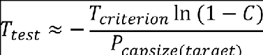 where: (A) *Ttest* is the required full-scale duration of the test (in seconds); (B) *Pcapsize(target)* is the required maximum probability of capsizing within 5 minutes; (C) *Tcriterion* is the duration (in seconds) in which the rotorcraft must meet the no-capsize probability (= 5 x 60 s), as defined in [CS 27.801(e)](#_DxCrossRefBm472493312); and (D) *C* is the required confidence that the probability of capsizing has been achieved (0.95). If the rotorcraft has capsized *Ncapsize* times during the tests, the probability of capsizing within 5 minutes can be estimated as:  and the confidence that the required capsize criteria have been met is:   It should be noted that, if the rotorcraft is permitted to fly over sea conditions with significant wave heights (*Hs*) above the certification limit, then *Pcapsiz(target)* should be reduced by the probability of exceedance of the certification limit for the significant wave height (*Pe*) (see [Appendix 2](#_DxCrossRefBm472493389) below). (c) Deliverables (1) A comprehensive report describing the model tests, the facility they were performed in, the model properties, the wave conditions used, the results of the tests, and the method of analysis to demonstrate compliance with [CS 27.801(d) and (e)](#_DxCrossRefBm472493312). (2) Conclusions in this report are to clarify the compliance (or otherwise) with those provisions. (3) Digital video and data records of all tests performed. (4) A specification for a certification model test should also be expected to include: (i) an execution plan and timescale; (ii) formal progress reports on content and frequency; and (iii) quality assurance requirements. [Amdt No: 27/5] --- [[4]](#_ftnref4) Rotors touching the waves can promote capsize, but they can also be a stabilising factor depending on the exact circumstances. Furthermore, rotor blades are often lost during the ditching due to contact with the sea. It is therefore considered acceptable to omit them from the model. [[5]](#_ftnref5) In general the model cannot be permitted to float freely in the basin because in the necessarily long-wave test durations, the model would otherwise drift down the basin and out of the calibrated wave region. Constraining the model to remain beam-on to the waves and not float freely is regarded as a conservative approach to the capsize test. A free-floating test is optional after a specific capsize event, in order to investigate whether the restraint system contributed to the event. It may also be possible to perform a complete free-floating test campaign by combining many short exposures in a wave basin capable of demonstrating a large calibrated wave region. [[7]](#_ftnref7) Wind generally has a tendency to redirect the rotorcraft nose into the wind/waves, thus reducing the likelihood of capsize. Therefore, this conservative testing approach does not include a wind simulation. [[8]](#_ftnref8) Each 5-minute exposure might not be independent if, for example, there was flooding of the rotorcraft, progressively degrading its stability. However, in this context, it is considered that the assumption of independence is conservative.
AMC2 27.801(e) and 27.802(c) Model test method for flotation stability ED Decision 2023/001/R This AMC should be used when showing compliance with [CS 27.801(e)](#_DxCrossRefBm8893881) or [CS 27.802(c)](#_DxCrossRefBm8893880) as introduced at Amendment 5. (a) Explanation (1) Model test objectives The objective of the model tests described in the certification specification is to establish the performance of the rotorcraft in terms of its stability in waves. The wave conditions in which the rotorcraft is to be certified should be selected according to the desired level of operability (see (a)(2) below). This will enable the overall performance of the rotorcraft to be established for inclusion in the rotorcraft flight manual (RFM) as required by [CS 27.1587(b)(3)](#_DxCrossRefBm8893965). In the case of approval with ditching provisions, the wave conditions selected for substantiation of behaviour during the water entry phase must also be taken into account. The rotorcraft design is to be tested, at each mass condition (see paragraph b(1)(ii) below), with its flotation system intact, and with its single most critical flotation compartment damaged (i.e. the single-puncture case which has the worst adverse effect on flotation stability). (2) Model test wave conditions The rotorcraft is to be tested in a single sea condition comprising a single combination of significant wave height (Hs) and zero-crossing period (Tz). The values of Hs and Tz should be no less than, and no more than, respectively, those chosen for certification, i.e. as selected from table 1. This approach is necessary in order to constrain the quantity of testing required within reasonable limits and is considered to be conservative. The justification is detailed in [Appendix 2](#_DxCrossRefBm8893963). The applicant is at liberty to certify the rotorcraft to any significant wave height Hs. This significant wave height will be noted as performance information in the RFM. Using reliable wave climate data for an appropriate region of the ocean for the anticipated flight operations, a Tz is selected to accompany the Hs. This Tz should be typical of those occurring at Hs as determined in the wave scatter table for the region. The mode or median of the Tz distribution at Hs should be used. It is considered that the northern North Sea represents a conservatively ‘hostile’ region of the ocean worldwide and should be adopted as the default wave climate for certification. However, this does not preclude an applicant from certifying a rotorcraft specifically for a different region. Such a certification for a specific region would require the geographical limits of that certification region to be noted as performance information in the RFM. Certification for the default northern North Sea wave climate does not require any geographical limits. In the case of an approval with emergency flotation provisions, operational limitations may limit flight to ‘non-hostile’ sea areas. For simplicity, the northern North Sea may still be selected as the wave climate for certification, or alternatively a wave climate derived from a non-hostile region’s data may be used. If the latter approach is chosen, and it is desired to avoid geographical limits, a ‘non-hostile’ default wave climate will need to be agreed with EASA. Wave climate data for the northern North Sea were obtained from the United Kingdom Meteorological Office (UK Met Office) for a typical ‘hostile’ helicopter route. The route selected was from Aberdeen to Block 211/27 in the UK sector of the North Sea. Data tables were derived from a UK Met Office analysis of 34 years of 3-hourly wave data generated within an 8-km, resolved wave model hindcast for European waters. This data represents the default wave climate. Table 1 below has been derived from this data and contains combinations of Hs and Tz. Table 1 also includes the probability of exceedance (Pe) of the Hs. Table 1 — Northern North Sea wave climate <table border="1" cellpadding="0" cellspacing="0" width="607"><thead><tr><td valign="top" width="35"><p></p></td><td colspan="4" valign="top" width="572"><p><b>Spectrum shape: JONSWAP, peak enhancement factor γ = 3.3</b></p></td></tr><tr><td valign="top" width="35"><p></p></td><td valign="top" width="143"><p><b>Significant wave height <i>Hs</i></b></p></td><td valign="top" width="143"><p><b>Mean wave period <i>Tz</i></b></p></td><td valign="top" width="143"><p><b>Significant steepness</b></p><p><b><i>Ss = 2πHs/(gTz2)</i></b></p></td><td valign="top" width="143"><p><b>Hs probability of exceedance <i>Pe</i></b></p></td></tr></thead><tr><td rowspan="10" valign="top" width="35"><p><b>Intact flotation system</b></p></td><td valign="top" width="143"><p>6 m </p></td><td valign="top" width="143"><p>7.9 s </p></td><td valign="top" width="143"><p>1/16.2 </p></td><td valign="top" width="143"><p>1.2 % </p></td></tr><tr><td valign="top" width="143"><p>5.5 m </p></td><td valign="top" width="143"><p>7.6 s </p></td><td valign="top" width="143"><p>1/16.4 </p></td><td valign="top" width="143"><p>2 % </p></td></tr><tr><td valign="top" width="143"><p>5 m </p></td><td valign="top" width="143"><p>7.3 s </p></td><td valign="top" width="143"><p>1/16.6 </p></td><td valign="top" width="143"><p>3 % </p></td></tr><tr><td valign="top" width="143"><p>4.5 m </p></td><td valign="top" width="143"><p>7.0 s </p></td><td valign="top" width="143"><p>1/17.0 </p></td><td valign="top" width="143"><p>5 % </p></td></tr><tr><td valign="top" width="143"><p>4 m </p></td><td valign="top" width="143"><p>6.7 s </p></td><td valign="top" width="143"><p>1/17.5 </p></td><td valign="top" width="143"><p>8 % </p></td></tr><tr><td valign="top" width="143"><p>3.5 m </p></td><td valign="top" width="143"><p>6.3 s </p></td><td valign="top" width="143"><p>1/17.7 </p></td><td valign="top" width="143"><p>13 % </p></td></tr><tr><td valign="top" width="143"><p>3 m </p></td><td valign="top" width="143"><p>5.9 s </p></td><td valign="top" width="143"><p>1/18.1 </p></td><td valign="top" width="143"><p>20 % </p></td></tr><tr><td valign="top" width="143"><p>2.5 m </p></td><td valign="top" width="143"><p>5.5 s </p></td><td valign="top" width="143"><p>1/18.9 </p></td><td valign="top" width="143"><p>29 % </p></td></tr><tr><td valign="top" width="143"><p>2 m </p></td><td valign="top" width="143"><p>5.1 s </p></td><td valign="top" width="143"><p>1/20.3 </p></td><td valign="top" width="143"><p>43 % </p></td></tr><tr><td valign="top" width="143"><p>1.25 m </p></td><td valign="top" width="143"><p>4.4 s </p></td><td valign="top" width="143"><p>1/24.2 </p></td><td valign="top" width="143"><p>72 % </p></td></tr></table> (3) Target probability of capsizing Target probabilities of capsizing have been derived from a risk assessment. The target probabilities to be applied are as stated in [CS 27.801(e)](#_DxCrossRefBm8893881) and [27.802(c)](#_DxCrossRefBm8893880), as applicable. For ditching, the intact flotation system probability of capsizing of 3 % is derived from a historic ditching rate of 3.32 x 10⁻⁶ per flight hour and an AC 27.1309 consequence of hazardous, which implies a frequency of capsizing of less than 10-7 per flight hour. The damaged flotation system probability of capsizing is increased by a factor of 10 to 30 % on the assumption that the probability of failure of the critical float compartment is 0.1; this probability has been estimated, as there is insufficient data on flotation system failure rates. For emergency flotation equipment, an increase of half an order (√10) is allowed on the assumption of a reduced exposure to the risk, resulting in a probability of capsizing of 10 %. The probability of a capsizing with a damaged flotation system is consequently increased to 100 %, hence no test is required. (4) Intact flotation system For the case of an intact flotation system, if the northern North Sea default wave climate has been chosen for certification, the rotorcraft should be shown to resist capsize in a sea condition selected from Table 1. The probability of capsizing in a 5-minute exposure to the selected sea condition is to be demonstrated to be less than or equal to the appropriate value provided in [CS 27.801(e)](#_DxCrossRefBm8893881) or [27.802(c)](#_DxCrossRefBm8893880), as appropriate, with a confidence of 95 % or greater. (5) Damaged flotation system For the case of a damaged flotation compartment (see (1) above), the same sea condition may be used, but a 10-fold increased probability of capsizing is permitted. This is because it is assumed that flotation system damage will occur in approximately one out of ten emergency landings on water. Thus, the probability of capsizing in a 5-minute exposure to the sea condition is to be demonstrated to be less than or equal to 10 times the required probability for the intact flotation system case, with a confidence of 95 % or greater. Where a 10-times probability is equal to or greater than 100 %, it is not necessary to perform a model test to determine the capsize probability with a damaged flotation system. Alternatively, the applicant may select a wave condition with 10 times the probability of exceedance Pe of the significant wave height (Hs) selected for the intact flotation condition. In this case, the probability of capsizing in a 5-minute exposure to the sea condition is to be demonstrated to be less than or equal to the required value (see [CS 27.801(e)](#_DxCrossRefBm8893881) or [27.802(c)](#_DxCrossRefBm8893880)), with a confidence of 95 % or greater. (6) Long-crested waves Whilst it is recognised that ocean waves are in general multidirectional (short-crested), the model tests are to be performed in unidirectional (long-crested) waves, this being regarded as a conservative approach to capsize probability. (b) Procedures (1) Rotorcraft model (i) Construction and scale of the model The rotorcraft model, including its emergency flotation, is to be constructed to be geometrically similar to the full-scale rotorcraft design at a scale that will permit the required wave conditions to be accurately represented in the model basin. It is recommended that the scale of the model should be not smaller than 1/15. The construction of the model is to be sufficiently light to permit the model to be ballasted to achieve the desired weight and rotational inertias specified in the mass conditions (see (b)(1)(ii) below)[[3]](#_ftn3). Where it is likely that water may flood into the internal spaces following an emergency landing on water, for example through doors opened to permit escape, or any other opening, the model should represent these internal spaces and openings as realistically as possible. It is permissible to omit the main rotor(s) from the model, but its (their) mass is to be represented in the mass and inertia conditions[[4]](#_ftn4). (ii) Mass conditions As it is unlikely that the most critical condition can be determined reliably prior to testing, the model is to be tested in two mass conditions: (A) maximum mass condition, mid C of G; and (B) minimum mass condition, mid C of G. (iii) Mass properties The model is to be ballasted in order to achieve the required scale weight, centre of gravity, roll and yaw inertia for each of the mass conditions to be tested. Once ballasted, the model’s floating draft and trim in calm water is to be checked and compared with the design floating attitude. The required mass properties and floating draft and trim, and those measured during model preparation, are to be fully documented and compared in the report. (iv) Model restraint system The primary method of testing is with a restrained model, but an alternative option is for a free-floating model (See (3)(iii) below). For the primary restrained method, a flexible restraint or mooring system is to be provided to restrain the model in order for it to remain beam-on to the waves in the model basin[[5]](#_ftn5). This restraint system should fulfil the following criteria: (A) be attached to the model on the centre line at the front and rear of the fuselage in such a position that roll motion coupling is minimised; an attachment at or near the waterline is preferred; and (B) be sufficiently flexible that the natural frequencies of the model surging/swaying on this restraint system are much lower than the lowest wave frequencies in the spectrum. (v) Sea anchor Whether or not the rotorcraft is to be fitted with a sea anchor, such an anchor is not to be represented in these model tests[[6]](#_ftn6). (2) Test facility The model test facility is to have the capability to generate realistic long non-repeating sequences of unidirectional (long-crested) irregular waves, as well as the characteristic wave condition at the chosen model scale. The facility is to be deep enough to ensure that the waves are not influenced by the depth (i.e. deep-water waves). The dimensions of the test facility are to be sufficiently large to avoid any significant reflection/refraction effects influencing the behaviour of the rotorcraft model. The facility is to be fitted with a high-quality wave-absorbing system or beach. The model basin is to provide full details of the performance of the wave maker and the wave absorption system prior to testing. (3) Model test set-up (i) General The model is to be installed in the wave facility in a location sufficiently distant from the wave maker, tank walls and beach/absorber such that the wave conditions are repeatable and not influenced by the boundaries. The model is to be attached to the model restraint system (see (b)(1)(iv) above). (ii) Instrumentation and visual records During wave calibration tests, three wave elevation probes are to be installed and their outputs continuously recorded. These probes are to be installed at the intended model location, a few metres to the side and a few metres ahead of this location. The wave probe at the model location is to be removed during tests with the rotorcraft model present. All tests are to be continuously recorded on digital video. It is required that at least two simultaneous views of the model are to be recorded. One is to be in line with the model axis (i.e. viewing along the wave crests), and the other is to be a three-quarter view of the model from the up-wave direction. Video records are to incorporate a time code to facilitate synchronisation with the wave elevation records in order to permit the investigation of the circumstances and details of a particular capsize event. (iii) Wave conditions and calibration Prior to the installation of the rotorcraft model in the test facility, the required wave conditions are to be pre-calibrated. Wave elevation probes are to be installed at the model location, alongside and ahead of the intended model location. The intended wave spectrum is to be run for the full exposure duration required to demonstrate the required probability of capsizing. The analysis of these wave calibration runs is to be used to: (A) confirm that the required wave spectrum has been obtained at the model location; and (B) verify that the wave spectrum does not deteriorate appreciably during the run in order to help establish the maximum duration test that can be run before the test facility must be allowed to become calm again. It should be demonstrated that the wave spectrum measured at each of the three locations is the same. If a free-floating model is to be used, then the waves are to be calibrated for a range of locations down the basin, and the spectrum measured in each of these locations should be shown to be the same. The length of the basin covered by this range will be the permitted test region for the free-floating model, and the model will be recovered when it drifts outside this region (See Section 4). It should be demonstrated that the time series of the waves measured at the model location does not repeat during the run. Furthermore, it should be demonstrated that one or more continuation runs can be performed using exactly the same wave spectrum and period, but with different wave time series. This is to permit a long exposure to the wave conditions to be built up from a number of separate runs without any unrealistic repetition of the time series. No wind simulation is to be used[[7]](#_ftn7). (iv) Required wave run durations The total duration of runs required to demonstrate that the required probability of capsizing has been achieved (or bettered) is dependent on that probability itself, and on the reliability or confidence of the capsize probability required to be demonstrated. With the assumption that each 5-minute exposure to the wave conditions is independent, the equations provided in (b)(5) below can be used to determine the duration without a capsize that is required to demonstrate the required performance.[[8]](#_ftn8) (See [Appendix 1](#_DxCrossRefBm8893964) below for examples.) (4) Test execution and results Tests are to start with the model at rest and the wave basin calm. Following the start of the wave maker, sufficient time is to elapse to permit the slowest (highest-frequency) wave components to arrive at the model, before data recording starts. Wave runs are to continue for the maximum permitted duration determined in the wave calibration test, or in the flee-floating option for as long as the model remains in the calibrated wave region. Following sufficient time to allow the basin to become calm again, additional runs are to be conducted until the necessary total exposure duration (Ttest) has been achieved (see (b)(5) below). In the case of the free-floating option, the model may be recovered and relaunched without stopping the wave maker, provided that the maximum permitted duration is not exceeded. See paragraph (4)(iv) for requirements regarding relaunching the free-floating model. If and when a model capsize occurs, the time of the capsize from the start of the run is to be recorded, and the run stopped. The model is to be recovered, drained of any water, and reset in the basin for a continuation run to be performed. There are a number of options that may be taken following a capsize event: (i) Continuing with the same model configuration. If the test is to be continued with the same model configuration, the test can be restarted with a different wave time series, or continued from the point of capsizing in a pseudorandom time series. (ii) Reducing the wave severity to achieve certification at a lower significant wave height. Provided that the same basic pseudorandom wave time series can be reproduced by the wave basin at a lower wave height and corresponding period, it is permitted to restart the wave maker time series at a point at least 5 minutes prior to the capsize event, and if the model is now seen to survive the wave sequence that caused a capsize in the more severe condition, then credit can then be taken for the run duration successfully achieved prior to the capsize. Clearly, such a restart is only possible with a model basin using pseudorandom wave generation. This method is only permitted if the change in significant wave height and period is sufficiently small that the same sequence of capsizing waves, albeit at a lower amplitude, can be seen in the wave basin. If this is not the case, then credit cannot be taken for the exposure time prior to capsize, and the wave time series must be restarted from the beginning. (iii) Modifying the model with the intention of avoiding a capsize. If it is decided to modify the model flotation with the intention of demonstrating that the modified model does not capsize in the wave condition, then the pseudorandom wave maker time series should be restarted at a point at least 5 minutes prior to the capsize event so that the model is seen to survive the wave that caused a capsize prior to the modification. Credit can then be taken for the duration of the run successfully achieved prior to the capsize. (iv) Repeating a restrained capsize event with a free-floating model. If it is suspected that the model restraint system might have contributed to the capsize event, it is permitted to repeat that part of the pseudorandom time series with a free-floating model. The model is to be temporally restrained with light lines and then released beam-on to the waves such that the free-floating model is seen to experience the same wave time series that caused a capsize in exactly the same position in the basin. It is accepted that it might require several attempts to find the precise model release time and position to achieve this. If the free-floating model, having been launched beam-on to the waves, is seen to yaw into a more beneficial heading once released, and seen to survive the wave that caused a capsize in the restrained model, then this is accepted as negating the capsize seen with the restrained model. The test may then continue with a restrained model as with (i) above. (v) Special considerations regarding relaunching a free-floating model into the calibrated wave region. If a free-floating model is being used for the tests, then it is accepted that the model will need to be recovered as it leaves the calibrated wave region, and then relaunched at the top of that region. It is essential that this process does not introduce any statistical or other bias into the behaviour of the model. For example, there might be a natural tendency to wait for a spell of calmer waves into which to launch the model. This particular bias is to be avoided by strictly obeying a fixed time delay between recovery and relaunch. Any water accumulated inside the model is not to be drained prior to the relaunch. If the model has taken up a heading to the waves that is not beam-on, then it is permissible to relaunch the model at that same heading. In all the above cases, continuation runs are to be performed until the total duration of exposure to the wave condition is sufficient to establish that the 5-minute probability of capsizing has been determined with the required confidence of 95 %. (5) Results analysis Given that it has been demonstrated that the wave time series are non-repeating and statistically random, the results of the tests may be analysed on the assumption that each 5-minute element of the total time series is independent. If the model rotorcraft has not capsized during the total duration of the tests, the confidence that the probability of capsizing within 5 minutes is less than the target value of Pcapsize(target), as shown below:   and so the total duration of the model test required without capsize is provided by: 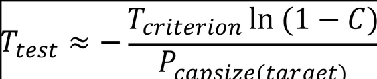 where: (A) *Ttest* is the required full-scale duration of the test (in seconds); (B) *Pcapsize(target)* is the required maximum probability of capsizing within 5 minutes; (C) *Tcriterion* is the duration (in seconds) in which the rotorcraft must meet the no-capsize probability (= 5 x 60 s), as defined in [CS 27.801(e)](#_DxCrossRefBm8893881); and (D) *C* is the required confidence that the probability of capsizing has been achieved (0.95). If the rotorcraft has capsized *Ncapsize* times during the tests, the probability of capsizing within 5 minutes can be estimated as:  and the confidence that the required capsize criteria have been met is:   It should be noted that, if the rotorcraft is permitted to fly over sea conditions with significant wave heights (*Hs*) above the certification limit, then *Pcapsiz(target)* should be reduced by the probability of exceedance of the certification limit for the significant wave height (*Pe*) (see [Appendix 2](#_DxCrossRefBm8893963) below). (c) Deliverables (1) A comprehensive report describing the model tests, the facility they were performed in, the model properties, the wave conditions used, the results of the tests, and the method of analysis to demonstrate compliance with [CS 27.801(d) and (e)](#_DxCrossRefBm8893881). (2) Conclusions in this report are to clarify the compliance (or otherwise) with those provisions. (3) Digital video and data records of all tests performed. (4) A specification for a certification model test should also be expected to include: (i) an execution plan and timescale; (ii) formal progress reports on content and frequency; and (iii) quality assurance requirements. [Amdt No: 27/5] --- [[4]](#_ftnref4) Rotors touching the waves can promote capsize, but they can also be a stabilising factor depending on the exact circumstances. Furthermore, rotor blades are often lost during the ditching due to contact with the sea. It is therefore considered acceptable to omit them from the model. [[5]](#_ftnref5) In general the model cannot be permitted to float freely in the basin because in the necessarily long-wave test durations, the model would otherwise drift down the basin and out of the calibrated wave region. Constraining the model to remain beam-on to the waves and not float freely is regarded as a conservative approach to the capsize test. A free-floating test is optional after a specific capsize event, in order to investigate whether the restraint system contributed to the event. It may also be possible to perform a complete free-floating test campaign by combining many short exposures in a wave basin capable of demonstrating a large calibrated wave region. [[7]](#_ftnref7) Wind generally has a tendency to redirect the rotorcraft nose into the wind/waves, thus reducing the likelihood of capsize. Therefore, this conservative testing approach does not include a wind simulation. [[8]](#_ftnref8) Each 5-minute exposure might not be independent if, for example, there was flooding of the rotorcraft, progressively degrading its stability. However, in this context, it is considered that the assumption of independence is conservative.