MOC VTOL.2215 Flight load conditions
n/a
The following flight load conditions specify a set of flight conditions to be evaluated to conservatively cover the most extreme manoeuvring capability of the aircraft. They should be analysed with the aircraft in the most critical flight phases and flight configurations, in accordance with the design limitations as defined in MOC VTOL.2200. The flight load cases may be simulated or defined by combining conservative combinations of parameters, or a combination of these approaches. Full control input ranges should be considered when determining the flight load cases. The limitations imposed by the flight control system, without failure cases, may be taken into account.
Failure conditions need not be considered, except as specified in paragraph (h) of this MOC.
If automation systems, such as autopilot upper modes, or a Detect and Avoid system can generate higher control loads than pilot inputs, the corresponding loads should be taken into account.
Suddenly. For the purposes of this MOC, ‘suddenly’ is defined as the time interval for complete control input based on a rational analysis, supported by test. For conventional pilot controls, such as stick and pedal, ‘suddenly’ may be assumed as 0.2 seconds for complete control inputs.
(a) Symmetrical Flight Load Conditions: To produce these flight load conditions, the airspeeds should be set at VD in forward, rearward and sideward flight. The normal load factor should be unity.
(b) Symmetrical pull-up and recovery: To produce these flight load conditions, with the aircraft in an initial trim condition at forward speeds:
(1) Displace the input control suddenly in order to achieve a nose up motion, to the maximum deflection as limited by the control stops;
(2) Maintain the maximum input control displacement to allow the aircraft to pitch upwards and achieve the specified positive manoeuvring load factor; and
(3) Return the input control suddenly to that required for level flight.
The most critical initial trim forward speeds should be evaluated, up to and including VD. This flight load condition should be evaluated in both power on and power off rpm ranges, if applicable.
The intention of the symmetric pull-up and recovery manoeuvre is to achieve maximum pitch acceleration, maximum positive normal load factor and maximum aircraft nose-up angle-of attack.
(c) Symmetrical Pushover and Recovery:
To produce these flight load conditions, with the aircraft in an initial trim condition at forward speed :
(1) Displace the input control suddenly, in order to achieve a nose down motion, to the maximum deflection as limited by the control stops;
(2) Maintain the maximum input control displacement to allow the aircraft to pitch downwards and achieve the specified negative manoeuvring load factor; and
(3) Return the input control suddenly to that required for level flight.
The most critical initial trim forward speeds should be evaluated, up to and including VD.
The intention of the symmetric pushover and recovery manoeuvre is to achieve maximum pitch acceleration, maximum negative normal load factor and maximum aircraft nose-down angle-of attack.
(d) Rolling Flight Conditions (Rolling pull-up and recovery):
To produce these flight load conditions, with the aircraft in an initial trim condition at forward speed:
(1) Displace the input control suddenly, in order to achieve a nose up and rolling moment, to the maximum deflection as limited by the control stops, or that necessary to achieve a positive load factor of not less than two-thirds that specified in paragraph (b);
(2) Maintain the control displacements to allow the aircraft to pitch, roll and achieve a positive manoeuvring load factor of at least two-thirds that specified in (b); and
(3) Return the controls suddenly to those required for level flight.
The maximum rate of roll and the load factor should occur simultaneously. The most critical initial trim forward speeds should be evaluated, up to and including VD.
The intention of the rolling pull-up and recovery manoeuvre is to achieve maximum pitch acceleration, maximum roll acceleration with two-thirds of the maximum positive normal load factor.
(e) Yawing Conditions:
To produce these flight load conditions, with the aircraft in an initial trim condition, with zero yaw, at forward speeds and in the hover:
(1) Displace the input control suddenly, in order to achieve a yawing motion, to the maximum deflection as limited by the control stops;
(2) Maintain the input control displacement to allow the aircraft to yaw to the maximum transient sideslip angle;
(3) Allow the aircraft to attain the resulting sideslip angle; and
(4) Return the directional control suddenly to neutral.
Both right and left yaw conditions should be evaluated. The most critical initial trim forward speeds should be evaluated, from zero up to and including VNE or VH, whichever is less.
Yawing conditions in the hover (spot turns) should be evaluated in both in ground effect (IGE) and out of ground effect (OGE).
The intention of the yawing condition is to achieve maximum yaw acceleration and maximum aircraft sideslip angles.
(f) Gust Conditions:
(2) The aircraft should be designed to withstand, at each critical airspeed up to VH or VNE, whichever is lower, including hovering, the loads resulting from vertical and horizontal gusts of 15.24 metres per second (50 ft/s).
(4) The aircraft should be designed to withstand 100% of the vertical gust condition of (0) acting on one side of the aircraft.
(5) The following assumptions should be made:
(i) For wing structures, the shape of the vertical gust is –
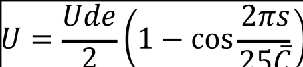
Where –
s = Distance penetrated into gust (ft);

Ude = Derived gust velocity referred to in paragraphs (1) to (3)
(ii) For other structures, and for horizontal gusts, either sharp-edged (instantaneous) gusts or sharp-edged gusts modified by an alleviation (attenuation) factor may be used for calculating aerodynamic loads for the aircraft and any installed stabilizing surfaces.
(g) Take-off from sloping ground
(1) The aircraft should be designed for take-off from level ground and up to the maximum slope and aircraft orientation combinations permitted for operation
(2) Vertical lift/thrust should be the maximum achievable for the take-off configuration of the aircraft
(3) This condition should be evaluated in both in ground effect (IGE) and out of ground effect (OGE)
(h) Unsymmetrical loads due to lift/thrust unit failure:
(1) The aircraft should be designed for unsymmetrical loads resulting from the failure of the critical lift/thrust unit, including blade release, at speeds up to VD including hover.
(2) The timing and magnitude of the probable pilot or automated corrective action should be conservatively estimated, considering the characteristics of the particular lift/thrust unit and aircraft combination.
(3) In the case of no corrective action being automatically performed, pilot corrective action, may be assumed to be initiated at the time maximum pitching, rolling or yawing velocity is reached, but not earlier than 2 seconds after the lift/thrust unit failure.
(4) Characterisation of the lift/thrust failure may be considered using analysis in lieu of an instantaneous loss of lift/thrust if appropriate, but should be done in a rational and conservative manner, and appropriately verified by test.