MOC VTOL.2115 Take-off performance
n/a
Testing of the take-off and landing procedures should take into consideration the “flight crew with average skills” and not be performed in particularly favourable atmospheric conditions. This implies that the performance associated with these procedures should not be determined through a single test, but rather be the result of multiple tests and take into account the normal variability of the results.
1. Introduction to take-off paths:
(a) Helicopter Category A foresees two possible take-off paths, one for Conventional Take-Off (ConvTO) and another for Elevated ConvTO (EConvTO) (Figure 1). The EConvTO differs from the ConvTO operation in that a dropdown below the surface level is allowed provided obstacle clearances (15ft of edge clearance) are maintained until reaching the take-off safety speed VTOSS (defined below). These two take-off paths are applicable to the VTOL capable aircraft with some adaptations for the VTOL flight mechanics.
(b) A third take-off path, Vertical Take-Off (VTO) (Figure 1), is also proposed with the objective of providing an adapted take-off path for VTOL urban environment operations from vertiports (see “Vertical take-off and landing procedure” in section 13):
(1) Obstacle clearance is established from the height h2, which is set at the top of the vertical climb.
(2) The protection surfaces are established at the height h2, since the minimum gradients should be determined and demonstrated after reaching VTOSS.
(3) During the vertical segment, it should be possible to perform a Rejected Take-Off (RTO) before reaching the Take-off Decision Point (TDP). Visual or synthetic cues can be used. Examples of synthetic cues include cameras and other trajectory guidance systems. The intended function of the synthetic cues should be clear, and their reliability should meet the safety objectives.
(4) After the TDP it should be possible to perform a Continued Take-off (CTO). The applicant may choose to have a pure vertical or a backup (rearward) take-off trajectory. The maximum deviations from the nominal trajectories should be determined and agreed with the Agency.
(5) The TDP can be placed at any point along the trajectory. Some applicants might elect to have a TDP lower than the top of the vertical segment, if the RTO cannot be performed safely from a given height upwards while meeting the Certified Minimum Performance (CMP) following a Critical Failure for Performance (CFP). Others may set the TDP at the bottom of the vertical segment because the RTO is not a foreseen option.
(c) The differences between the three profiles lie only at the initial portion of the take-off trajectory and acceleration to forward flight, until VTOSS and a positive rate of climb (RoC) are achieved. The trajectories on Figure 1 are depicted considering that a CFP occurs soon after the TDP. A common minimum take-off path definition after VTOSS is possible (Figure 2).
(d) The engine power settings considered are not those already used for conventional turbine engines. For VTOL capable aircraft with electric propulsion, there are at the moment no specific ratings such as the 10 minutes take-off AEO rating, the 30 sec or 2 min. rating, the 2,5 min OEI rating, etc. The power ratings will be defined at project level, as they will depend on the overall configuration (rotor-borne or wing-borne), number of engines, and also failure cases (number of acceptable engine losses). Figure 2 depicts the trajectories and the engine power settings while considering the most critical condition: a Critical Failure for Performance (CFP) during the take-off phase at TDP.
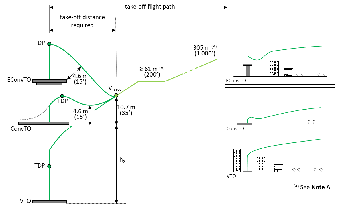
Figure 1: Possible take-off paths
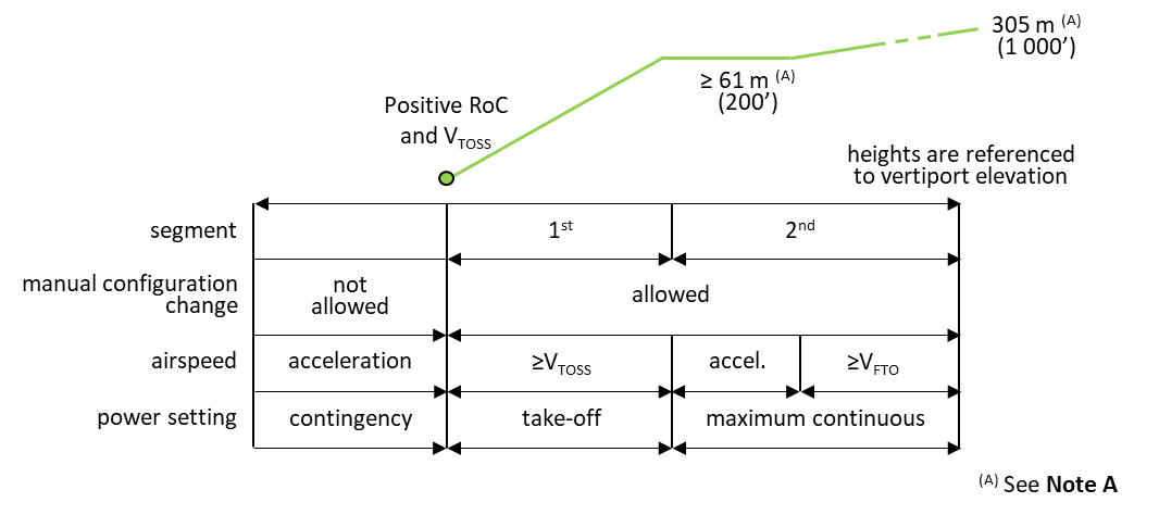
Figure 2: Take-off path segments definitions, after VTOSS is achieved following a CFP at TDP
2. Approved take-off paths
(a) The take-off path extends from the take-off point to a point at which the aircraft is 305 m (1 000 ft) above the take-off elevation at the final take-off configuration.
Note A: The altitudes of 61 m (200 ft) and 305 m (1 000 ft) are proposed in the development of the take-off flight path as currently used for Category A helicopters. Different take-off heights can be considered if compatible with the departure and en-route profile.
(b) The aircraft should be accelerated to VTOSS while clearing any surface by 4.6 m (15 ft).
(c) The aircraft should reach VTOSS and should continue at speeds not less than VTOSS, until it is 61 m (200 ft) above the take-off elevation, with a minimum gradient of climb at each point. The minimum gradients, derived from CS-27 and CS-29, are 4.5 % for the first segment and 2.5 % for the second segment.
(d) For ConvTO, VTOSS should be reached at or before 10.7 m (35 ft) above the take-off elevation. In the dropdown segment, in normal and CFP, not less than 4.6 m (15 ft) clearance to the take-off elevation is allowed.
(e) For the EConvTO, the aircraft may descend below the level of the take-off surface if, in so doing and when clearing the elevated vertiport edge, in normal and CFP, every part of the aircraft clears all obstacles by at least 4.6m (15 ft). The vertical magnitude of any descent below the take-off surface should be determined and published.
(f) For the VTO, VTOSS should be reached at or before 10.7 m (35 ft) above h2. The Vertical take-off and landing procedure is described in section 13 of this MOC.
(g) The aircraft configuration (e.g. tilt wings/thrust units, flaps, gear) and power settings (contingency/take-off and maximum continuous power) may automatically change along the take-off path. Configuration changes requiring action by the crew are allowed only after the aircraft reaches VTOSS.
(h) Starting at the point at which the aircraft reaches 61 m (200 ft) above the take-off elevation (or above h2), the aircraft should be accelerated to the Final Take-off Speed (VFTO) and should then be capable of a directional trajectory change with at least 3°/s:
(1) When reaching VFTO while changing directional trajectory, the aircraft should be capable of maintaining at least level flight (no descent).
(2) If the applicant elects to show compliance to the Handling Qualities requirements using the Modified Handling Qualities Rating (MHQRM), specific manoeuvres to replicate this condition should be proposed.
(3) The effect of turn rates on the minimum climb gradients, including a standard turn rate of 3°/s, should be demonstrated and published.
(4) The corresponding maximum turn radius should be measured and published.
(5) The applicant can choose to demonstrate that the aircraft can follow curved approach and take-off climb surfaces as per ICAO Annex 14, volume 2, chapter 4 or better. The effect on the minimum climb gradients should then be demonstrated and published.
3. Take-off Decision Point (TDP)
(a) The TDP is the first point defined by a combination of speed and height from which CTO is demonstrated meeting the CMP, and is the last point in the take-off path from which an RTO is assured.
(b) The Pilot’s Intervention Time after a failure, including CFP for take-off, should be set not less than 1 second, and the Pilot’s Recognition Time not less than 0.5 second, for a Pilot’s Reaction Time after the CFP of not less than 1.5 second. The pilot input, and the decision to CTO or RTO, is expected to happen after the Reaction Time is elapsed. Depending on the aircraft characteristics, cockpit and physical information, the Pilot’s Recognition Time and/or the Pilot’s Intervention Time might be longer, and therefore need to be evaluated.
Note: The take-off performance should be determined for all associated mass, atmospheric and wind conditions (see MOC VTOL.2105) so that, in case of the occurrence of the CFP event at any time after the start of take-off, the aircraft can either return to, and stop safely on the take-off area, or continue the take-off and climb out.
Note: The Pilot’s Reaction time is the sum of the Pilot’s Recognition time plus the Pilot’s Intervention time. The Pilot’s Recognition time is the time counted from the onset of the failure until the pilot is made aware of it. The Pilot’s Intervention time is the time elapsed from the moment the pilot is made aware of the failure until an input to the flight controls is made.
4. Take-off Safety Speed (VTOSS)
(a) Only primary control inceptors should be used while attaining VTOSS and while establishing the required climb gradient.
(b) VTOSS should be reached without requiring configuration changes commanded by the crew.
(c) VTOSS should be demonstrated for each weight, most critical centre of gravity position, altitude, and temperature for which take-off data are to be determined. It should also include sufficient margin for the limiting (negative) vertical wind velocity and turbulences.
(d) Flying at VTOSS should provide a steady gradient of climb of at least 4.5 % at the power rate setting declared by the applicant for the first take-off segment.
5. Final Take-off Speed (VFTO)
(a) Any control can be used while attaining VFTO and while establishing the required climb gradient, however this should not be done before an appropriate pilot’s reaction time when considering a CFP condition.
(b) VFTO can be reached and maintained requiring configuration changes, including landing gear retraction, commanded by the flight crew.
(c) VFTO should be determined for each weight, most critical centre of gravity position, altitude, and temperature for which take-off data are to be determined.
(d) Flying at VFTO should provide a steady gradient of climb of at least 2.5 % at maximum continuous power and a manoeuvring capability of not less than 3°/s of turn rate while not descending.
6. Dimension “D”
(a) The diameter ‘D’ is the diameter of the smallest circle enclosing the VTOL capable aircraft projection on a horizontal plane, while the aircraft is in the take-off or landing configuration, with rotor(s) turning if applicable (Figure 3).
(b) The diameter D should be published in metres and feet, rounded up to the next tenth.
(c) If the VTOL capable aircraft changes its dimensions during taxi or parking (e.g. folding wings), a corresponding Dtaxi and Dparking should also be provided.
(a) The heights h1 and h2 for VTOLs are the equivalent of In Ground Effect (IGE) and Out of Ground Effect (OGE) hover for rotorcraft. Because there could be no actual beneficial “ground effect” on performance of hovering close to the ground for all VTOL designs, the conventional IGE and OGE terms have been considered to be no longer applicable. Applicants may decide to establish h1 and h2 values based on other considerations, such as handling qualities or ground clearance following failure conditions. See also Section 13 “Vertical take-off and landing procedure” in this MOC.
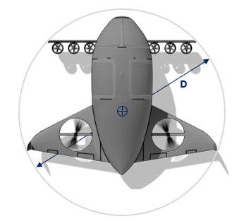
Figure 3: Centre and diameter ‘D’ of the smallest enclosing circle
8. Centre of the smallest enclosing circle
(a) The location (e.g. STA and BL) of the centre of the smallest enclosing circle used to determine D should be established and published (Figure 3).
(b) If the VTOL capable aircraft changes its dimensions during taxi or parking (e.g. folding wings) and the positions of the centre of the smallest enclosing circle varies, the corresponding locations should also be provided.
9. FATO width required
(a) ‘Final approach and take-off area’ (FATO) means a defined area over which the final phase of the approach manoeuvre to hover or land is completed and from which the take-off manoeuvre is commenced.
(b) The FATO includes the rejected take-off area.
(c) The FATO width required should be established and published in metres and feet, rounded up to the next tenth.
10. Take-off distance required (TODRV)
(a) ‘Take-off distance’ (TOD) means the projected horizontal distance from the start of a take-off procedure to:
(1) For ConvTO: the point where the aircraft reaches 10.7 m (35 ft) above the take-off surface with the minimum climb gradient of 4.5 %; or
(2) For EConvTO: after the dropdown segment, the point where the aircraft reaches 10.7 m (35 ft) above the take-off surface with the minimum climb gradient of 4.5%; or
(3) For VTO: the point where the aircraft reaches 10.7 m (35 ft) above h2 (defined in section 13 of this MOC) with the minimum climb gradient of 4.5 %.
(b) The TOD required for VTOL capable aircraft (TODRV) that provides safe obstacle clearance following a CFP being recognized at TDP should be established and published in metres and feet, rounded up to the next tenth.
11. Rejected take-off distance required
(RTODRV)
(a) ‘Rejected take-off distance’ (RTOD) means the length of the FATO required by the VTOL capable aircraft to complete a rejected take-off in accordance with the Category in which it is operated, Enhanced or Basic. This value is provided in the AFM for comparison with the RTOD available for the FATO.
(b) The RTOD required for VTOL capable aircraft (RTODRV) that provides safe containment following a CFP being recognized at TDP should be established and published in metres and feet, rounded up to the next tenth.
12. TLOF size required
(a) ‘Touchdown and lift-off area’ (TLOF) means an area on which a VTOL capable aircraft may touch down or lift off.
(b) The TLOF size (length and width) required for approved procedures should be established and published in metres and feet, rounded up to the next tenth.
(c) The minimum dimensions should be the larger of:
(1) the minimum size of the surface to contain the undercarriage;
(2) the aircraft performance scatter during a landing after a Critical Failure for Performance (CFP) to a specific reference point; and
(3) the surface required to provide the minimum suitable visual cues for a landing after a CFP.
13. Vertical take-off and
landing procedure
(a) The applicant may provide a procedure for a vertical take-off and landing, with a vertical segment from the ground facilitating clearance of obstacles, for example in the urban environment (Figure 4 and Figure 5).
(b) The AFM should then include the following values:
|
Parameter |
Short description |
Minimum/maximum1 |
Reference volume Type 12 |
|
h1 |
Low hover height |
- |
3 m (10 ft) |
|
h2 |
High hover height |
≥ h1 |
30.5 m (100 ft) |
|
TOwidth |
Width at h2 |
≤ 5 D |
2 D |
|
TOfront |
Front distance at h2 |
≤ 5 D |
1.5 D |
|
TOback |
Back distance at h2 |
≤ 5 D |
1.5 D |
|
FATOwidth |
Width of the FATO |
≥ 1.5 D |
1.5 D |
|
FATOfront |
Front distance on FATO |
≥ 0.75 D |
0.75 D |
|
FATOback |
Back distance on FATO |
≥ 0.75 D |
0.75 D |
|
θapp |
Slope of approach surface |
≥ 4.5% |
12.5 % |
|
θdep |
Slope of departure surface |
≥ 4.5% |
12.5 % |
Note 1: “Minimum/maximum” corresponds to the minimum or maximum values acceptable for certification.
Note 2: See (f)
(c) The published values should represent trajectories obtained with procedures demonstrated to be consistently executable without requiring exceptional piloting skill, alertness, or strength in atmospheric conditions expected to be encountered in service, as required by VTOL.2105(c).
(d) FATOfront and FATOback are referenced to the aircraft centre of the smallest enclosing circle (see section 8. of this MOC). TOfront and TOback are measured from a vertical line passing through the same point. The values published should ensure the containment of the aircraft during the procedure, for example TOback will be larger for a back-up take-off procedure and FATOfront should consider the Rejected take-off distance (RTOD).
(e) The rest of the take-off procedure (e.g. take-off decision point, drop down, climb segments) should be designed with respect to the horizontal plane at h2
(f) The applicant may develop one or multiple procedures within the maximum/minimum values provided in (b). A specific volume, called “Reference volume Type 1”, can also be proposed with standardised values that can be useful for vertiport design in an obstacle rich environment (Figure 6 and Figure 7). Demonstrating during certification that the aircraft can reliably conduct take-off and landings in this volume is offered as a possibility to the applicant to facilitate the integration in corresponding vertiports.
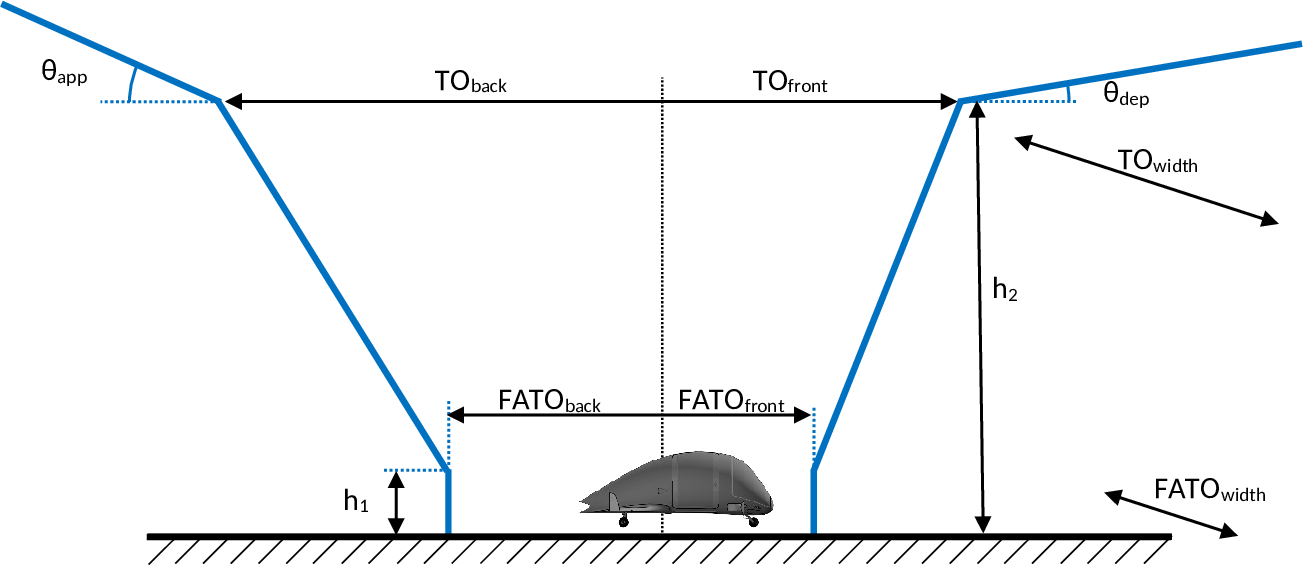
Figure 4: Generic vertical take-off and landing procedure parameters, side view
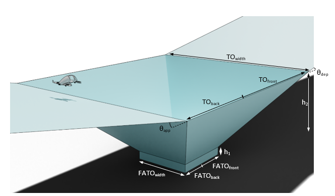
Figure 5: Generic vertical take-off and landing procedure parameters, perspective view
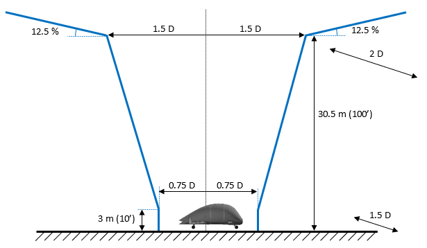
Figure 6: “Reference volume Type 1” vertical take-off and landing procedure parameters, side view
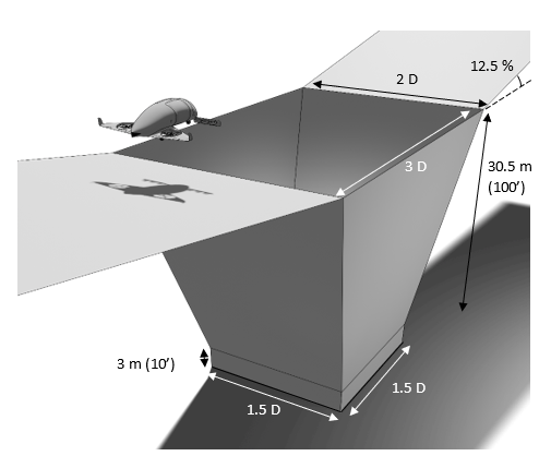
Figure 7: “Reference volume Type 1” vertical take-off and landing procedure parameters, perspective view
14. Overall width
(a) ‘Overall width’ means the widest lateral width of the VTOL capable aircraft projection on a horizontal plane, while the aircraft is in the take-off or landing configuration, with rotor(s) turning if applicable.
(b) The overall width should be established and published in metres and feet, rounded up to the next tenth.
(c) If the VTOL capable aircraft lateral width changes during taxi or parking (e.g. folding wings), a corresponding overall width during taxi or parking should also be provided.
15. Overall length
(a) ‘Overall length’ means the longest longitudinal length of the VTOL capable aircraft projection on a horizontal plane, while the aircraft is in the take-off or landing configuration, with rotor(s) turning if applicable.
(b) The overall length should be established and published in metres and feet, rounded up to the next tenth.
(c) If the VTOL capable aircraft length changes during taxi or parking (e.g. retracting tail), a corresponding overall length during taxi or parking should also be provided.
16. Undercarriage width (UCW)
(a) ‘Undercarriage width’ (UCW) means the width of the undercarriage/landing gear projection on a horizontal plane (Figure 8).
(b) The undercarriage width should be established and published in metres and feet, rounded up to the next tenth.
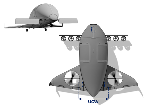
Figure 8: Undercarriage width
17. Undercarriage footprint
(a) ‘Undercarriage’ footprint means the diameter of the circle containing the landing gear contact area while the aircraft is in the take-off or landing configuration (Figure 9). The undercarriage footprint can be used for the determination of the undercarriage containment area and TLOF (touchdown and lift-off area).
(b) The undercarriage footprint should be established and published in metres and feet, rounded up to the next tenth.
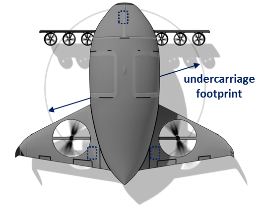
Figure 9: Undercarriage footprint
18. Hover and ground (if applicable) turn
diameter required
The diameters of the containment area required to perform a 360-degree turn in a normal operation hover and ground-taxi (if applicable) should be established and published in metres and feet, rounded up to the next tenth.
19. Aircraft Flight Manual Data:
The following data, defined in the previous sections of this MOC, should be included in the AFM:
(a) Approved take-off paths
(b) Take-off decision point
(c) Take-off Safety Speed (VTOSS)
(d) Final Take-off Speed (VFTO)
(e) Dimension “D”
(f) Hover heights h1 and h2 (if applicable)
(g) Centre of the smallest enclosing circle
(h) FATO width required
(i) Take-off distance required for VTOL capable aircraft (TODRV)
(j) Rejected take-off distance required for VTOL capable aircraft (RTODRV)
(k) TLOF size required
(l) Vertical take-off and landing procedure (if applicable)
(m) Overall width
(n) Overall length
(o) Undercarriage width (UCW)
(p) Undercarriage footprint
(q) Hover and ground (if applicable) turn diameter required