Appendix 6 Completion of a flight plan
Regulation (EU) 2024/404
1. ICAO MODEL FLIGHT PLAN FORM
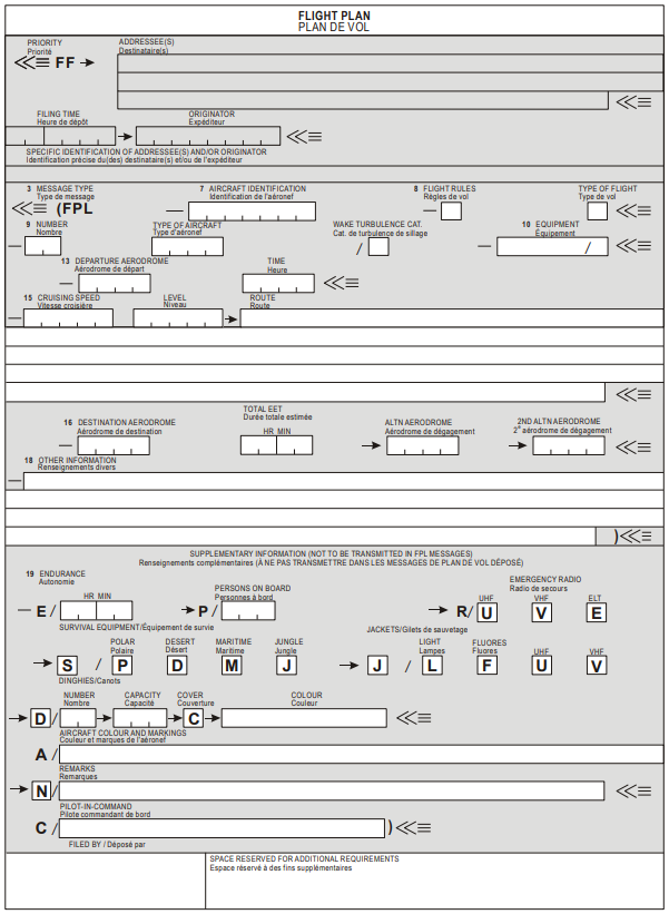
2. INSTRUCTIONS FOR THE COMPLETION OF THE FLIGHT PLAN FORM
2.1 General
Adhere closely to the prescribed formats and manner of specifying data.
Commence inserting data in the first space provided. Where excess space is available, leave unused spaces blank.
Insert all clock times in 4 figures UTC.
Insert all estimated elapsed times in 4 figures (hours and minutes).
The shaded area preceding item 3 – shall be completed by ATS and COM services, unless the responsibility for originating flight plan messages has been delegated.
2.2 Instructions for insertion of ATS data
Complete items 7 to 18 and, when so required by the competent authority or otherwise deemed necessary, item 19 as indicated hereunder.
ITEM
7: AIRCRAFT IDENTIFICATION
(MAXIMUM
7 CHARACTERS)
INSERT one of the following aircraft identifications, not exceeding 7 alphanumeric characters and without hyphens or symbols:
(a) the ICAO designator for the aircraft operator followed by the flight identification (e.g. KLM511, NGA213, JTR25) when in radiotelephony the call sign to be used by the aircraft consists of the ICAO telephony designator for the operator followed by the flight identification (e.g. KLM511, NIGERIA 213, JESTER 25); or
(b) the nationality or common mark and registration mark of the aircraft (e.g. EIAKO, 4XBCD, N2567GA), when:
(1) in radiotelephony the call sign to be used by the aircraft consists of this identification alone (e.g. CGAJS), or preceded by the ICAO telephony designator for the aircraft operator (e.g. BLIZZARD CGAJS);
(2) the aircraft is not equipped with radio.
ITEM
8: FLIGHT RULES AND TYPE OF FLIGHT (ONE OR TWO CHARACTERS)
Flight rules
INSERT one of the following letters to denote the category of flight rules with which the pilot intends to comply:
I – if it is intended that the entire flight is operated under IFR; or
V – if it is intended that the entire flight is operated under VFR; or
Y – if the flight is initially operated under IFR, followed by one or more subsequent changes of flight rules; or
Z – if the flight is initially operated under VFR, followed by one or more subsequent changes of flight rules.
Specify in Item 15 the point or points at which a change of flight rules is planned.
Type of flight
INSERT one of the following letters to denote the type of flight when so required by the competent authority:
S – if scheduled air service;
N – if non-scheduled air transport operation;
G – if general aviation;
M – if military;
X – if other than any of the defined categories above.
Specify status of a flight following the indicator STS in Item 18, or when necessary to denote other reasons for specific handling by ATS, indicate the reason following the indicator RMK in Item 18.
ITEM
9: NUMBER AND TYPE OF AIRCRAFT AND WAKE TURBULENCE CATEGORY
Number of aircraft (1 or 2 characters)
INSERT the number of aircraft, if more than one.
Type of aircraft (2 to 4 characters)
INSERT the appropriate designator as specified in Doc 8643, Aircraft Type Designators,
OR, if no such designator has been assigned, or in case of formation flights comprising more than one type,
INSERT ZZZZ, and SPECIFY in item 18 the (numbers and) type(s) of aircraft preceded by ‘TYP/ .
Wake turbulence category (1 character)
INSERT an oblique stroke followed by one of the following letters to indicate the wake turbulence category of the aircraft:
J – SUPER, to indicate an aircraft type specified as such in ICAO Doc 8643, Aircraft Type Designators, latest edition;
H – HEAVY, to indicate an aircraft type with a maximum certified take-off mass of 136 000 kg or more, with the exception of aircraft types listed in ICAO Doc 8643 in the SUPER (J) category;
M – MEDIUM, to indicate an aircraft type with a maximum certified take-off mass of less than 136 000 kg but more than 7 000 kg;
L – LIGHT, to indicate an aircraft type with a maximum certified take-off mass of 7 000 kg or less.
ITEM
10: EQUIPMENT AND CAPABILITIES
Capabilities comprise the following elements:
(a) presence of relevant serviceable equipment on board the aircraft;
(b) equipment and capabilities commensurate with flight crew qualifications; and
(c) where applicable, authorisation from the appropriate authority.
Radiocommunication, navigation and approach aid equipment and
capabilities
INSERT one letter as follows:
N – if no COM/NAV/approach aid equipment for the route to be flown is carried, or the equipment is unserviceable;
OR
S – if standard COM/NAV/approach aid equipment for the route to be flown is carried and serviceable;
AND/OR
INSERT one or more of the following letters to indicate the serviceable COM/NAV/approach aid equipment and capabilities available:
A GBAS landing system
B LPV (APV with SBAS)
C LORAN C
D DME
E1 FMC WPR ACARS
E2 D-FIS ACARS
E3 PDC ACARS
F ADF
G GNSS. If any portion of the flight is planned to be conducted under IFR, it refers to GNSS receivers that comply with the requirements of Annex 10, Volume I
H HF RTF
I Inertial Navigation
J1 CPDLC ATN VDL Mode 2
J2 CPDLC FANS 1/A HFDL
J3 CPDLC FANS 1/A VDL Mode A
J4 CPDLC FANS 1/A VDL Mode 2
J5 CPDLC
FANS 1/A SATCOM (INMARSAT)
J6 CPDLC
FANS 1/A SATCOM (MTSAT)
J7 CPDLC FANS 1/A SATCOM (Iridium)
K MLS
L ILS
M1 ATC SATVOICE (INMARSAT)
M2 ATC SATVOICE (MTSAT)
M3 ATC SATVOICE (Iridium)
O VOR
P1 CPDLC RCP 400
P2 CPDLC RCP 240
P3 SATVOICE RCP 400
P4-P9 Reserved for RCP
R PBN approved
T TACAN
U UHF RTF
V VHF RTF
W RVSM approved
X MNPS approved
Y VHF with 8.33 kHz channel spacing capability
Z Other equipment carried or other capabilities
Any alphanumeric characters not indicated above are reserved.
Surveillance equipment and capabilities
INSERT N if no surveillance equipment for the route to be flown is carried, or the equipment is unserviceable;
OR
INSERT one or more of the following descriptors, to a maximum of 20 characters, to describe the serviceable surveillance equipment and/or capabilities on board:
SSR Modes A and C
A – Transponder – Mode A (4 digits – 4 096 codes)
C – Transponder – Mode A (4 digits – 4 096 codes) and Mode C
SSR Mode S
E – Transponder – Mode S, including aircraft identification, pressure-altitude and extended squitter (ADS-B) capability
H – Transponder – Mode S, including aircraft identification, pressure-altitude and enhanced surveillance capability
I – Transponder – Mode S, including aircraft identification, but no pressure-altitude capability
L – Transponder – Mode S, including aircraft identification, pressure-altitude, extended squitter (ADS-B) and enhanced surveillance capability
P – Transponder – Mode S, including pressure-altitude, but no aircraft identification capability
S – Transponder – Mode S, including both pressure-altitude and aircraft identification capability
X – Transponder – Mode S with neither aircraft identification nor pressure-altitude capability
ADS-B
B1 – ADS-B with dedicated 1 090 MHz ADS-B “out” capability
B2 – ADS-B with dedicated 1 090 MHz ADS-B “out” and “in” capability
U1 – ADS-B “out” capability using UAT
U2 – ADS-B “out” and “in” capability using UAT
V1 – ADS-B “out” capability using VDL Mode 4
V2 – ADS-B “out” and “in” capability using VDL Mode 4
ADS-C
D1 – ADS-C with FANS 1/A capabilities
G1 – ADS-C with ATN capabilities
Alphanumeric characters not indicated above are reserved.
ITEM
13: DEPARTURE AERODROME AND TIME (8 CHARACTERS)
INSERT the ICAO 4-letter location indicator of the departure aerodrome as specified in Doc 7910, Location Indicators;
OR, if no location indicator has been assigned,
INSERT ZZZZ and SPECIFY, in Item 18:
— the name and location of the aerodrome preceded by DEP/; or
— the first point of the route or the marker radio beacon preceded by DEP/…, if the aircraft has not taken off from an aerodrome;
OR, – if the flight plan is received from an aircraft in flight,
INSERT AFIL, and SPECIFY, in Item 18, the ICAO 4-letter location indicator of the location of the ATS unit from which supplementary flight plan data can be obtained, preceded by DEP/.
THEN, WITHOUT A SPACE,
INSERT for a flight plan submitted before departure, the estimated off-block time (EOBT),
OR, for a flight plan received from an aircraft in flight, the actual or estimated time over the first point of the route to which the flight plan applies.
ITEM
15: ROUTE
INSERT the first cruising speed as in (a) and the first cruising level as in (b), without a space between them.
THEN, following the arrow, INSERT the route description as in (c).
(a) Cruising speed (maximum 5 characters)
INSERT the True airspeed for the first or the whole cruising portion of the flight, in terms of:
Kilometres per hour, expressed as K followed by 4 figures (e.g. K0830), or
Knots, expressed as N followed by 4 figures (e.g. N0485), or
True Mach number, when so prescribed by the appropriate ATS authority, to the nearest hundredth of unit Mach, expressed as M followed by 3 figures (e.g. M082).
(b) Cruising level (maximum 5 characters)
INSERT the planned cruising level for the first or the whole portion of the route to be flown, in terms of:
Flight level, expressed as F followed by 3 figures (e.g. F085; F330), or
Standard metric level in tens of metres, when so prescribed by the competent authority expressed as S followed by 4 figures (e.g. S1130), or
Altitude in hundreds of feet, expressed as A followed by 3 figures (e.g. A045; A100), or
Altitude in tens of metres, expressed as M followed by 4 figures (e.g. M0840), or
for uncontrolled VFR flights, the letters VFR.
(c) Route (including changes of speed level and/or flight rules
Flights along designated ATS routes
INSERT, if the departure aerodrome is located on or connected to the ATS route, the designator of the first ATS route,
OR, if the departure aerodrome is not on or connected to the ATS route, the letters DCT followed by the point of joining the first ATS route, followed by the designator of the ATS route.
THEN
INSERT each point at which either a change of speed and/or level is planned to commence, or a change of ATS route, and/or a change of flight rules is planned,
FOLLOWED IN EACH CASE
by the designator of the next ATS route segment, even if it is the same as the previous one,
OR by DCT, if the flight to the next point is outside a designated route, unless both points are defined by geographical coordinates.
Flights outside designated ATS routes
INSERT points normally not more than 30 minutes flying time or 370 km (200 NM) apart, including each point at which a change of speed or level, a change of track, or a change of flight rules is planned,
OR, when required by competent authority(ies),
DEFINE the track of flights operating predominantly in an east-west direction between 70°N and 70°S by reference to significant points formed by the intersections of half or whole degrees of latitude with meridians spaced at intervals of 10 degrees of longitude. For flights operating in areas outside those latitudes, the tracks shall be defined by significant points formed by the intersection of parallels of latitude with meridians normally spaced at 20 degrees of longitude. The distance between significant points shall, as far as possible, not exceed 1 hour’s flight time. Additional significant points shall be established as deemed necessary.
For flights operating predominantly in a north-south direction, define tracks by reference to significant points formed by the intersection of whole degrees of longitude with specified parallels of latitude which are spaced at 5 degrees.
INSERT DCT between successive points unless both points are defined by geographical coordinates or by bearing and distance.
USE ONLY the conventions in (1) to (5) below and SEPARATE each sub-item by a space.
ATS route (2 to 7 characters)
The coded designator assigned to the route or route segment including, where appropriate, the coded designator assigned to the standard departure or arrival route (e.g. BCN1, Bl, R14, UB10, KODAP2A).
Significant point (2 to 11 characters)
The coded designator (2 to 5 characters) assigned to the point (e.g. LN, MAY, HADDY),
or, if no coded designator has been assigned, one of the following ways:
— Degrees only (7 characters):
2 figures describing latitude in degrees, followed by “N” (North) or “S” (South), followed by 3 figures describing longitude in degrees, followed by “E” (East) or “W” (West). Make up the correct number of figures, where necessary, by insertion of zeros, e.g. 46N078W.
— Degrees and minutes (11 characters):
4 figures describing latitude in degrees and tens and units of minutes followed by “N” (North) or “S” (South), followed by 5 figures describing longitude in degrees and tens and units of minutes, followed by “E” (East) or “W” (West). Make up the correct number of figures, where necessary, by insertion of zeros, e.g. 4620N07805W.
— Bearing and distance from a reference point:
The identification of the reference point, followed by the bearing from the point in the form of 3 figures giving degrees magnetic, followed by the distance from the point in the form of 3 figures expressing nautical miles. In areas of high latitude where it is determined by the appropriate authority that reference to degrees magnetic is impractical, degrees true may be used. Make up the correct number of figures, where necessary, by insertion of zeros – e.g. a point 180° magnetic at a distance of 40 NM from VOR “DUB” should be expressed as DUB180040.
Change of speed or level (maximum 21 characters)
The point at which a change of speed (5 % TAS or 0,01 Mach or more) or a change of level is planned to commence, expressed exactly as in (2) above, followed by an oblique stroke and both the cruising speed and the cruising level, expressed exactly as in (a) and (b) above, without a space between them, even when only one of these quantities will be changed.
Examples: LN/N0284A045
MAY/N0305Fl80
HADDY/N0420F330
4602N07805W/N0500F350
46N078W/M082F330
DUB180040/N0350M0840
Change of flight rules (maximum 3 characters)
The point at which the change of flight rules is planned, expressed exactly as in (2) or (3) above as appropriate, followed by a space and one of the following:
VFR if from IFR to VFR
IFR if from VFR to IFR
Examples: LN VFR
LN/N0284A050 IFR
Cruise climb (maximum 28 characters)
The letter C followed by an oblique stroke; THEN the point at which cruise climb is planned to start, expressed exactly as in (2) above, followed by an oblique stroke; THEN the speed to be maintained during cruise climb, expressed exactly as in (a) above, followed by the two levels defining the layer to be occupied during cruise climb, each level expressed exactly as in (b) above, or the level above which cruise climb is planned followed by the letters PLUS, without a space between them.
Examples: C/48N050W/M082F290F350
C/48N050W/M082F290PLUS
C/52N050W/M220F580F620
ITEM
16: DESTINATION AERODROME AND TOTAL ESTIMATED ELAPSED TIME,
DESTINATION ALTERNATE AERODROME(S)
Destination aerodrome and total estimated elapsed time (8
characters)
INSERT the ICAO 4-letter location indicator of the destination aerodrome as specified in Doc 7910, Location Indicators,
OR, if no location indicator has been assigned,
INSERT ZZZZ and SPECIFY in Item 18 the name and location of the aerodrome, preceded by DEST/.
THEN WITHOUT A SPACE
INSERT the total estimated elapsed time.
Destination alternate aerodrome
INSERT the ICAO 4-letter location indicator(s) of not more than two destination alternate aerodromes, as specified in Doc 7910, Location Indicators, separated by a space,
OR, if no location indicator has been assigned to the destination alternate aerodrome(s),
INSERT ZZZZ and SPECIFY in Item 18 the name and location of the destination alternate aerodrome(s), preceded by ALTN/.
ITEM
18: OTHER INFORMATION
Hyphens or oblique strokes should only be used as prescribed below.
INSERT 0 (zero) if no other information,
OR, any other necessary information in the sequence shown hereunder, in the form of the appropriate indicator selected from those defined hereunder followed by an oblique stroke and the information to be recorded:
STS/ Reason for special handling by ATS, e.g. a search and rescue mission, as follows:
ALTRV: for a flight operated in accordance with an altitude reservation;
ATFMX: for a flight approved for exemption from ATFM measures by the competent authority;
FFR: firefighting;
FLTCK: flight check for calibration of navaids;
HAZMAT: for a flight carrying hazardous material;
HEAD: a flight with Head of State status;
HOSP: for a medical flight declared by medical authorities;
HUM: for a flight operating on a humanitarian mission
MARSA: for a flight for which a military entity assumes responsibility for separation of military aircraft;
MEDEVAC: for a life-critical medical emergency evacuation;
NONRVSM: for a non-RVSM-capable flight intending to operate in RVSM airspace;
SAR: for a flight engaged in a search and rescue mission; and
STATE: for a flight engaged in military, customs, or police services.
Other reasons for special handling by ATS shall be denoted under the designator “RMK/”.
PBN/ Indication of RNAV and/or RNP capabilities. Include as many of the descriptors below, as apply to the flight, up to a maximum of 8 entries, i.e. a total of not more than 16 characters.
RNAV SPECIFICATIONS
A1 RNAV 10 (RNP 10)
B1 RNAV 5 all permitted sensors
B2 RNAV 5 GNSS
B3 RNAV 5 DME/DME
B4 RNAV 5 VOR/DME
B5 RNAV 5 INS or IRS
B6 RNAV 5 LORANC
C1 RNAV 2 all permitted sensors
C2 RNAV 2 GNSS
C3 RNAV 2 DME/DME
C4 RNAV 2 DME/DME/IRU
D1 RNAV 1 all permitted sensors
D2 RNAV 1 GNSS
D3 RNAV 1 DME/DME
D4 RNAV 1 DME/DME/IRU
RNP SPECIFICATIONS
L1 RNP 4
O1 Basic RNP 1 all permitted sensors
O2 Basic RNP 1 GNSS
O3 Basic RNP 1 DME/DME
O4 Basic RNP 1 DME/DME/IRU
S1 RNP APCH
S2 RNP APCH with BARO-VNAV
T1 RNP AR APCH with RF (special authorization required)
T2 RNP AR APCH without RF (special authorization required)
Combinations of alphanumeric characters not indicated above are reserved.
NAV/ Significant data related to navigation equipment, other than specified in PBN/, as required by the competent authority.
Indicate GNSS augmentation under this indicator, with a space between two or more methods of augmentation, e.g. NAV/GBAS SBAS.
Indicate EURPRNAV if the aircraft approved P-RNAV relies solely on VOR/DME for the determination of position.
COM/ Indicate communication equipment and capabilities not specified in Item 10 a).
DAT/ Indicate data communication equipment and capabilities not specified in Item 10 a) or “CPDLCX” to indicate exemption granted from the requirement to be equipped with CPDLC-ATN-B1.
SUR/ Indicate surveillance equipment and capabilities not specified in Item 10 b). Indicate as many RSP specification(s) as apply to the flight, using designator(s) with no space. Multiple RSP specifications are separated by a space. Example: RSP180 RSP400.
Insert EUADSBX, EUEHSX, EUELSX, or a combination of them, to indicate exemptions granted for the requirement to be equipped with SSR Mode S transponders or ADS-B transmitters.
DEP/ Name and location of departure aerodrome, if ZZZZ is inserted in Item 13, or the ATS unit from which supplementary flight plan data can be obtained, if AFIL is inserted in Item 13. For aerodromes not listed in the relevant Aeronautical Information Publication, indicate location as follows:
With 4 figures describing latitude in degrees and tens and units of minutes followed by “N” (North) or “S” (South), followed by 5 figures describing longitude in degrees and tens and units of minutes, followed by “E” (East) or “W” (West). Make up the correct number of figures, where necessary, by insertion of zeros, e.g. 4620N07805W (11 characters).
OR, Bearing and distance from the nearest significant point, as follows:
The identification of the significant point followed by the bearing from the point in the form of 3 figures giving degrees magnetic, followed by the distance from the point in the form of 3 figures expressing NM. In areas of high latitude where it is determined by the appropriate authority that reference to degrees magnetic is impractical, degrees true may be used. Make up the correct number of figures, where necessary, by insertion of zeros, e.g. a point of 180° magnetic at a distance of 40 NM from VOR “DUB” should be expressed as DUB180040.
OR, The first point of the route (name or LAT/LONG) or the marker radio beacon, if the aircraft has not taken off from an aerodrome.
DEST/ Name and location of destination aerodrome, if ZZZZ is inserted in Item 16. For aerodromes not listed in the relevant Aeronautical Information Publication, indicate location in LAT/LONG or bearing and distance from the nearest significant point, as described under DEP/above.
DOF/ The date of flight departure in a 6-figure format (YYMMDD, where YY equals the year, MM equals the month, and DD equals the day).
REG/ The nationality or common mark and registration mark of the aircraft, if different from the aircraft identification in Item 7.
EET/ Significant points or FIR boundary designators and accumulated estimated elapsed times from take-off to such points or FIR boundaries, when so prescribed on the basis of regional air navigation agreements, or by the competent authority.
Examples: EET/CAP0745 XYZ0830
EET/EINN0204
SEL/ SELCAL Code, for aircraft so equipped.
TYP/ Type(s) of aircraft, preceded if necessary without a space by number(s) of aircraft and separated by one space, if ZZZZ is inserted in Item 9.
Example: TYP/2F15 5F5 3B2
CODE/ Aircraft address (expressed in the form of an alphanumerical code of 6 hexadecimal characters) when required by the competent authority. Example: “F00001” is the lowest aircraft address contained in the specific block administered by ICAO.
DLE/ En-route delay or holding, insert the significant point(s) on the route where a delay is planned to occur, followed by the length of delay using 4-figure time in hours and minutes (hhmm).
Example: DLE/MDG0030
OPR/ ICAO designator or name of the aircraft operator, if different from the aircraft identification in Item 7.
ORGN/ The originator’s 8-letter AFTN address or other appropriate contact details, in cases where the originator of the flight plan may not be readily identified, as required by the competent authority.
PER/ Aircraft performance data, indicated by a single letter as specified in the Procedures for Air Navigation Services – Aircraft Operations (PANS-OPS, Doc 8168), Volume I – Flight Procedures, if so prescribed by the competent authority.
ALTN/ Name of destination alternate aerodrome(s), if ZZZZ is inserted in Item 16. For aerodromes not listed in the relevant Aeronautical Information Publication, indicate location in LAT/LONG or bearing and distance from the nearest significant point, as described in DEP/above.
RALT/ ICAO 4-letter indicator(s) for en-route alternate(s), as specified in Doc 7910, Location Indicators, or name(s) of en-route alternate aerodrome(s), if no indicator is allocated. For aerodromes not listed in the relevant Aeronautical Information Publication, indicate location in LAT/LONG or bearing and distance from the nearest significant point, as described in DEP/above.
TALT/ ICAO 4-letter indicator(s) for take-off alternate, as specified in Doc 7910, Location Indicators, or name of take-off alternate aerodrome, if no indicator is allocated. For aerodromes not listed in the relevant Aeronautical Information Publication, indicate location in LAT/LONG or bearing and distance from the nearest significant point, as described in DEP/above.
RIF/ The route details to the revised destination aerodrome, followed by the ICAO 4-letter location indicator of the aerodrome. The revised route is subject to reclearance in flight.
Examples: RIF/DTA HEC KLAX
RIF/ESP G94 CLA YPPH
RVR/ minimum runway visual range requirement for the flight expressed in 3 figures.
RFP/ indication of the number of the replacement flight plans submitted in format “Q” followed by 1 figure indicating the iteration of replacement.
Examples: RFP/Q2.
RMK/ Any other plain-language remarks when required by the competent authority or deemed necessary.
ITEM
19: SUPPLEMENTARY INFORMATION
Endurance
After E/ INSERT a 4-figure group giving the fuel endurance in hours and minutes.
Persons on board
After P/ INSERT the total number of persons (passengers and crew) on board, when required by the competent authority. INSERT TBN (to be notified) if the total number of persons is not known at the time of filing.
Emergency and survival equipment
R/(RADIO) CROSS OUT U if UHF on frequency 243,0 MHz is not available.
CROSS OUT V if VHF on frequency 121,5 MHz is not available.
CROSS OUT E if emergency locator transmitter (ELT) is not available.
S/(SURVIVAL EQUIPMENT) CROSS OUT all indicators if survival equipment is not carried.
CROSS OUT P if polar survival equipment is not carried.
CROSS OUT D if desert survival equipment is not carried.
CROSS OUT M if maritime survival equipment is not carried.
CROSS OUT J if jungle survival equipment is not carried.
J/(JACKETS) CROSS OUT all indicators if life jackets are not carried.
CROSS OUT L if life jackets are not equipped with lights.
CROSS OUT F if life jackets are not equipped with fluorescein.
CROSS OUT U or V or both as in R/above to indicate radio capability of jackets, if any.
D/(DINGHIES) CROSS OUT indicators D and C if no dinghies are carried; or
(NUMBER) INSERT number of dinghies carried; and
(CAPACITY) – INSERT total capacity, in persons, of all dinghies carried; and
(COVER) – CROSS OUT indicator C if dinghies are not covered; and
(COLOUR) – INSERT colour of dinghies if carried.
A/(AIRCRAFT COLOUR INSERT colour of aircraft and significant markings.
AND MARKINGS)
N/(REMARKS) CROSS OUT indicator N if no remarks, or INDICATE any other survival equipment carried and any other remarks regarding survival equipment.
C/(PILOT) INSERT name of pilot-in-command.
2.3 Filed by
INSERT the name of the unit, the agency or the person filing the flight plan.