Appendix 5 to AMC1 FSTD(H).300 Transport delay
testing method
Decision 2012/011/R
(a) General
(1) The purpose of this Appendix is to demonstrate how to determine the introduced transport delay through the FSTD system such that it does not exceed a specific time delay. That is, measure the transport delay from control inputs through the interface, through each of the host computer modules and back through the interface to motion, flight instrument and visual systems, and show that it is no more than the tolerances required in the validation test tables.
(2) Four specific examples of transport delay are described as follows:
(i) simulation of classic non-computer controlled aircraft;
(ii) simulation of computer controlled aircraft using real aircraft equipment;
(iii) simulation of computer controlled aircraft using software emulation of aircraft equipment; and
(iv) simulation using software avionics or re-hosted instruments.
(3) Figure 1 illustrates the total transport delay for a non-computer-controlled aircraft, or the classic transport delay test.
(4) Since there are no aircraft-induced delays for this case, the total transport delay is equivalent to the introduced delay.
(5) Figure 2 illustrates the transport delay testing method employed on an FSTD that uses the real aircraft controller system.
(6) To obtain the induced transport delay for the motion, instrument and visual signal, the delay induced by the aircraft controller should be subtracted from the total transport delay. This difference represents the introduced delay.
(7) Introduced transport delay is measured from the cockpit control input to the reaction of the instruments, and motion and visual systems (See figure 1).
(8) Alternatively, the control input may be introduced after the aircraft controller system and the introduced transport delay measured directly from the control input to the reaction of the instruments, and FSTD motion and visual systems (See figure 2).
(9) Figure 3 illustrates the transport delay testing method employed on an FSTD that uses a software emulated aircraft controller system.
(10) By using the simulated aircraft controller system architecture for the pitch, roll and yaw axes, it is not possible to measure simply the introduced transport delay. Therefore, the signal should be measured directly from the pilot controller. Since in the real aircraft the controller system has an inherent delay as provided by the aircraft manufacturer, the FSTD manufacturer should measure the total transport delay and subtract the inherent delay of the actual aircraft components and ensure that the introduced delay does not exceed the tolerances required in the validation test tables.
(11) Special measurements for instrument signals for FSTDs using a real aircraft instrument display system, versus a simulated or re-hosted display. For the case of the flight instrument systems, the total transport delay should be measured, and the inherent delay of the actual aircraft components subtracted to ensure that the introduced delay does not exceed the tolerances required in the validation test tables.
(i) Figure 4A illustrates the transport delay procedure without the simulation of aircraft displays. The introduced delay consists of the delay between the control movement and the instrument change on the data bus.
(ii) Figure 4B illustrates the modified testing method required to correctly measure introduced delay due to software avionics or re-hosted instruments. The total simulated instrument transport delay is measured and the aircraft delay should be subtracted from this total. This difference represents the introduced delay and should not exceed the tolerances required in the validation test tables. The inherent delay of the aircraft between the data bus and the displays is indicated as XX ms (see figure 4A). The display manufacturer should provide this delay time.
(12) Recorded signals. The signals recorded to conduct the transport delay calculations should be explained on a schematic block diagram. The FSTD manufacturer should also provide an explanation of why each signal was selected and how they relate to the above descriptions.
(13) Interpretation of results. It is normal that FSTD results vary over time from test to test. This can easily be explained by a simple factor called ‘sampling uncertainty’. All FSTDs run at a specific rate where all modules are executed sequentially in the host computer. The flight controls input can occur at any time in the iteration, but these data should not be processed before the start of the new iteration. For an FSTD running at 60 Hz a worst‑case difference of 16.67 ms can be expected. Moreover, in some conditions, the host FSTD and the visual system do not run at the same iteration rate, therefore the output of the host computer to the visual will not always be synchronised.
(14) The transport delay test should account for the worst-case mode of operation of the visual system. The tolerance is as required in the validation test tables and motion response should occur before the end of the first video scan containing new information.
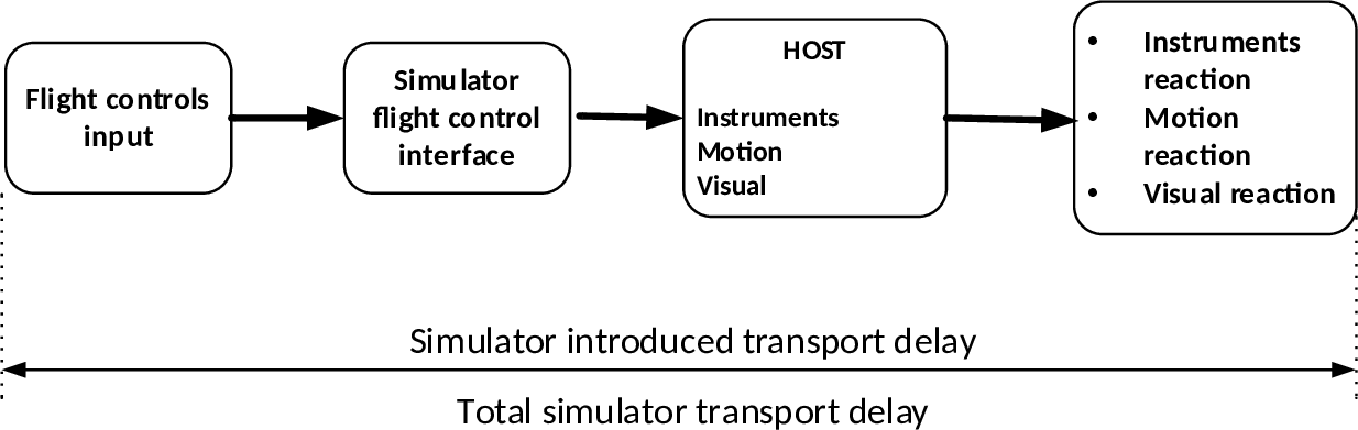
Figure 1:
Transport delay for simulation of classic non-computer-controlled aircraft
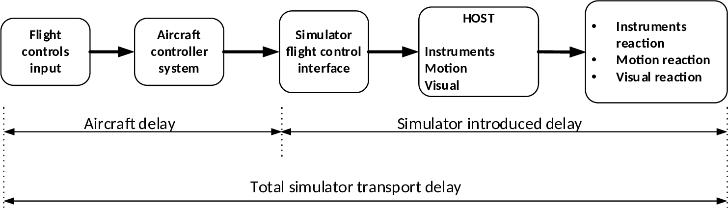
Figure 2:
Transport delay for simulation of computer-controlled aircraft using real
aircraft equipment
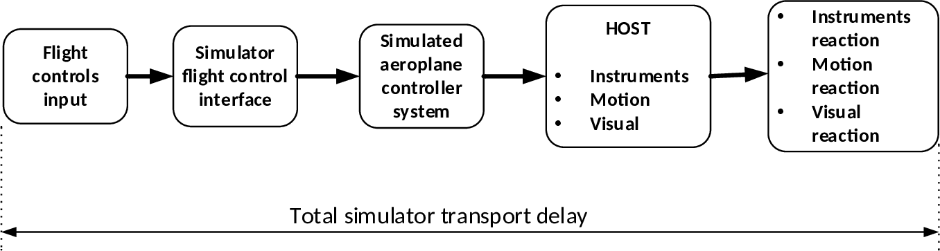
Figure 3: Transport
delay for simulation of computer-controlled aircraft using software emulation
of aircraft equipment
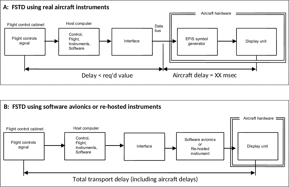
Figure 4A
and 4B: Transport delay for simulation of aircraft using real or re-hosted
instrument drivers