Appendix 3 to AMC1 FSTD(H).300 Rotor aerodynamic
modelling techniques
Decision 2012/011/R
(a) Introduction
Several modelling choices are available to simulate rotor blade aerodynamics. These include rotor disks, rotor maps, and blade element rotor models. Cost, simulation fidelity, and training requirements are three factors that may determine the appropriate model to use.
(b) Disk models
(1) Rotor disk models typically approximate blade flapping by the first few terms of a Fourier series. The lift curve is assumed to be a linear function of angle of attack and inflow is usually assumed to be uniform over the entire disk. With these assumptions the forces and moments produced by the blades over the course of one complete revolution can be written analytically. Blade azimuthal position can then be ignored by the rest of the helicopter aerodynamic model, which sees normalised forces as generated by a thrust producing disk. Disk models are usually easy to implement and tune, and require minimal computer resources to run. Disk models are best at matching static performance characteristics, and weakest in matching dynamic handling qualities and flight at extremes of the flight envelope where some of the underlying assumptions cease to be true. The risk is that these models may require an unmanageable accumulation of add‑ons to simulate all the helicopter effects that do not flow naturally out of the model such as blade stall, dynamic stall, reverse flow, and cross coupling effects. For certain helicopter types, and for many tail rotors, some of these effects will be negligible or occur outside of the civil flight envelope and thus not impact the training requirements of the FSTD. Adding the effects of sharp wind gradients over the rotor disk, which may occur in confined areas or in pinnacle training, is problematic, as the formulation assumes constant wind speed over the disk.
Figure
1
(c) Rotor map models
(1) Rotor map models, or coefficient models, are also not computationally demanding. With this method a database of coefficients or stability and control derivatives is used to compute aircraft forces and moments. The simulation should interpolate its performance from the nearest points in the database. This database can be generated from flight test data analysis or from an off-line blade element model. Steady state performance can in theory be easily tuned by simply adjusting data points in the database. However, if the database is generated from an off-line model blade element model then considerable effort could be spent tuning the off-line model that is one step removed from the simulation. The net result is a saving in real time execution, but development costs may be as high as a full blade element model. The blade element model that generates the database, since it runs off-line, is not limited by real time constraints and thus can be considerably more complex than real time blade element models.
FSTD fidelity may be limited by the overall size and coarseness of the database. Not every flight possibility should be covered by the database and separate databases may need to be generated to simulate failure modes. As with the rotor disk model the incorporation of known air flows into the simulation at the blade elements is problematic and could effect for example, the realism of simulated turbulence, and the effectiveness of confined area landing training where the winds have large gradients such that they will not be constant over the entire rotor disk.
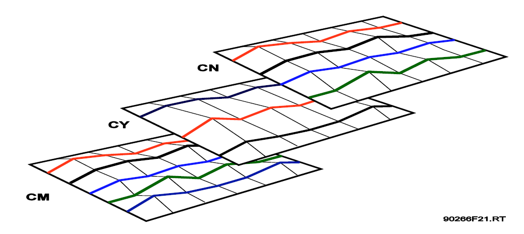
Figure 2
(d) Blade element rotor models
(1) A blade element rotor model has at its core a division of the blade into discrete segments. Rotor speed and radial station as well as local winds at each segment are used to compute local angle of attack, sideslip and Mach number. Using the airfoil characteristics of airfoil at the blade segment aerodynamic forces are computed. Once all the forces and moments for all segments have been computed the equations of motion of each blade are solved. Real time constraints may limit the number of segments, and the degrees of freedom/flexibility of the blades and the complexity of the inflow model. A real time blade element model and its associated inflow model are significantly more complex than a rotor disk, but offer a more rigorous simulation of a helicopter rotor blade dynamics. Blade motions even at very low rotor speeds are computed in the same manner, thus offering fidelity simulation of helicopter operations from rotor stopped, through start-up, to the full flight envelope including malfunctions and the effects of sharp wind gradients across the blade elements that occur in confined areas or in pinnacle training. The model can be used to provide helicopter vibrations amplitudes and trends.
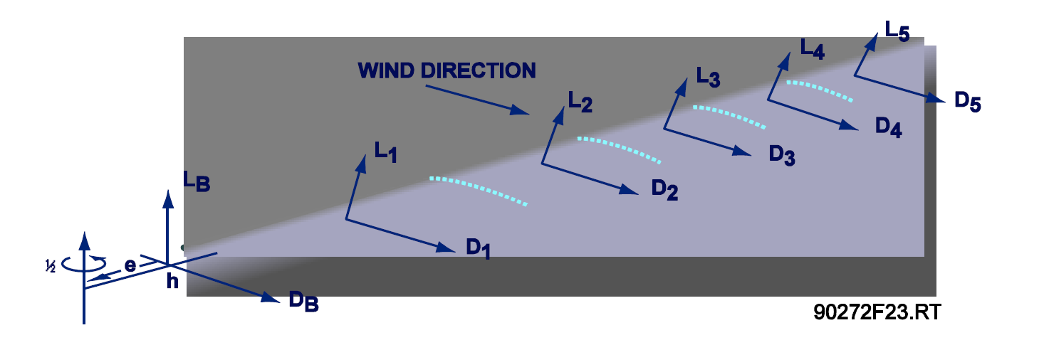
Figure 3
(e) Conclusions
(1) The modelling choice alone cannot ensure fidelity. The best guarantor of accurate simulation training remains validation with flight test data. A blade element rotor model reduces risk to simulation training by giving a more comprehensive rotor simulation, but comes at a price of increased complexity and computer resource requirements. This may be warranted where the training objectives of the simulation require a very high level of fidelity.