GM12 FSTD(A).300 Additional guidance on upset
prevention and recovery training (UPRT) for the FSTD Standards table
ED Decision 2018/006/R
(a) Introduction The FSTD should be provided with information pertaining to the aeroplane’s parameters as described in AMC12 FSTD(A).300. This AMC details some of the performance provisions for these features.
The objective of the IOS feedback during UPRT exercises is to provide the instructor with the ability to assess the timely and proper control action, including sequence, to complete the recovery in a safe manner.
(b) Background IOS feedback, which may also be via a separate mobile device, is used to monitor and debrief the crew regarding UPRT exercises in order to verify that proper control activity was executed. The instructor should have the necessary information to clearly establish whether the recovery was completed within the FSTD training envelope (please refer to AMC12 FSTD(A).300), and take any necessary action to complete the training.
The FSTD should include tools for the instructor to be able to immediately debrief the pilot(s) after the training event. All data recorded for the use in the UPRT debrief should be easily permanently deleted after the UPRT training event.
(c) IOS parameters
The tool should normally display:
(1) Pilot-induced control inputs, including:
(i) pitch,
(ii) roll,
(iii) rudder pedal,
(iv) throttles,
(v) flaps, and
(vi) speed brake/spoilers.
Time history of control inputs, including cockpit control forces and flight control law (fly-by-wire aeroplanes), as applicable.
In order to ascertain that the control inputs are applied in a correct, timely and smooth manner, the display should indicate these at a sampling frequency rate that is sufficiently high to prevent from missing possible abrupt pilot action. This may be limited to the debrief mode following the execution of the exercise or individual manoeuvre.
(2) Display of the primary flight parameters; if applicable, display a copy of the Primary Flight Display (PFD); if a PFD is displayed, then the parameters shall be the same as the ones displayed on the aeroplane PFD, including:
(i) pitch attitude,
(ii) roll attitude,
(iii) turn/sideslip,
(iv) indicated airspeed,
(v) stall warning speed/stall buffet speed,
(vi) VMO/MMO,
(vii) altitude,
(viii) rate of climb,
(ix) autopilot status, and
(x) auto-throttle status.
(3) Angle of attack.
(4) Angle of sideslip.
(5) G-loading.
The limitations of (3), (4), and (5) shall also be indicated, as follows:
One method is the simultaneous depiction of the angle of attack versus angle of sideslip and the corresponding FSTD validation envelope.
A presentation of the G-loading as function of the current airspeed and flight configuration.
The V-n diagram indicates the limitations of the aeroplane under given conditions. It displays the flight envelope as function of the airspeed versus G-loading. It shows the lower airspeed limits by means of a parabolic line. The intersection of this line with the 1.0g horizontal line corresponds to the stall speed at 1g. The regions above the 2.5g upper limit (maximum design limit) to the right of VNE and below the – 1.0g lower limit are the structural exceedance limits and should be avoided. The shape of the V-n diagram depends on the aeroplane itself, its configuration, as well as the environmental and flight conditions.
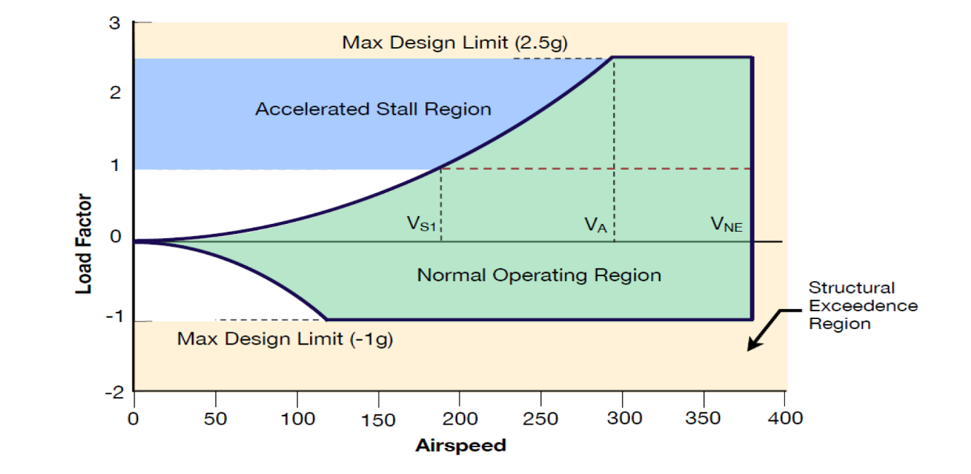
Figure
1 — V-n diagram (example)
Legend to Figure 1:
VS1 = clean stall speed at 1g
VA = design manoeuvre speed
VNE = never-exceed speed
[Issue: CS-FSTD(A)/2]