Appendix 2.2 to ETSO-C153a – Integrated Modular Avionics (IMA) Platform and Module Minimum Performance Standard (MPS)
ED Decision 2020/011/R
This Appendix contains the Minimum Performance Standards (MPS) for the CLASS RH Intended Function: Rack Housing.
These standards specify module characteristics that should be useful to designers, manufacturers, installers and users of the IMA module.
1.2. Definitions
For ETSO-C153a CLASS RH, the IMA module is a physical package able to contain at least two hardware modules, which may provide partial protection from environmental effects (shielding, etc.) and enable the installation and removal of those module(s) from the aircraft without physically altering other aircraft systems or equipment.
These IMA modules may be simple mechanical enclosures, or they may incorporate passive communication interfaces, a passive interconnection of data and power, an active or passive cooling unit or any combination of these features.
The following definitions are used:
— ‘Mounted’ refers to another hardware module, installed and fixed inside the IMA rack module, after a human operation.
— ‘Slot’ is a physical space inside the rack module, allocated to one hardware module.
These definitions are independent of the design choices made by the IMA module manufacturer.
Note:
— The IMA module compliant with ETSO-C153a CLASS RH MPS is only relevant in the case of an IMA platform architecture that uses a cabinet; and
— hardware modules mounted inside the Rack Housing will themselves be IMA modules (compliant with ETSO-C153a MPS classes other than RH) or non-IMA modules (i.e. non-IMA application specific hardware).
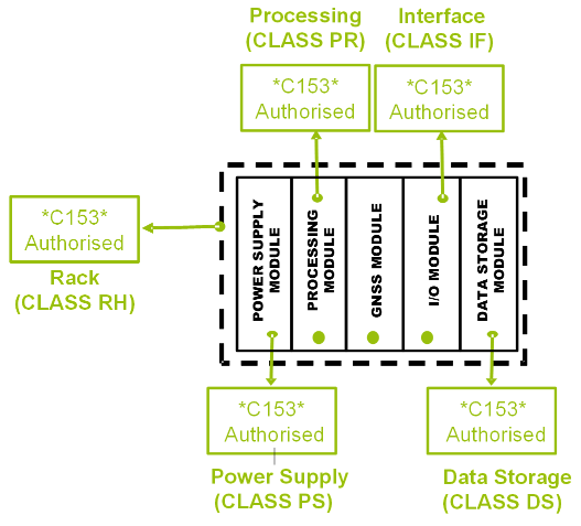
Figure 5: Illustration of the IMA platform architecture based on a cabinet
For ETSO-C153a CLASS RH, the intended function is to provide the capability to share some of the housing services supplied by one mechanical unit.
This intended function can be divided into 4 sub-functions:
— F1: Housing (mandatory);
— F2: Shielding (optional);
— F3: Interconnection (optional); and
— F4: Temperature control (optional).
Figure 6 provides an overview of the above-mentioned intended functions and definitions of the Rack Housing Module.
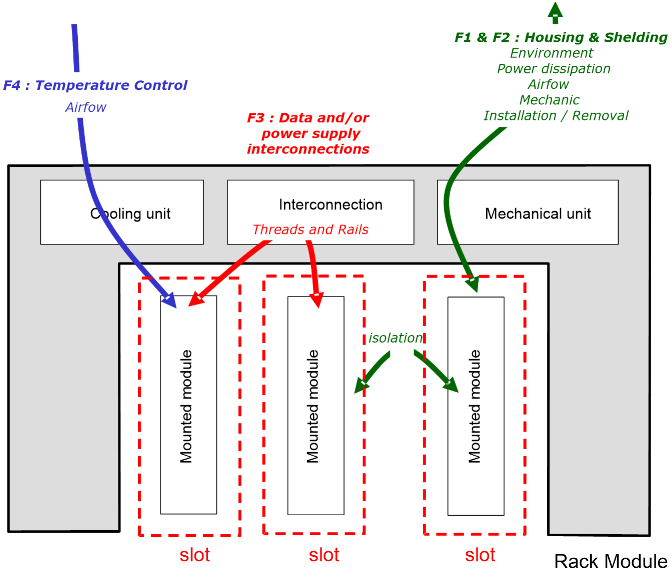
Figure 6: IMA module overview for ETSO-C153a CLASS RH
2. Requirements
2.1. Requirements for Housing (F1)
For ETSO-C153a CLASS RH, the IMA module provides shared resources for the housing needs of hardware modules. This sub-function merges:
— the capacity to host at least two hardware modules in at least two slots; and
— the capacity to mount and dismount a hardware module in its slot directly on the aircraft thanks to a human (potentially tooled) intervention.
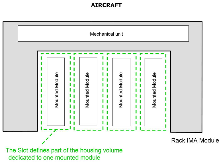
Figure 7: CLASS RH Housing function overview
2.1.1. Functional requirements for ETSO-C153a CLASS RH (F1): Housing
RH.a) The Rack Housing shall permit the installation and attachment of at least two hardware modules to be installed and attached, one of which (at least) is an IMA module, inside its mechanical structure.
RH.b) The Rack Housing shall ensure the physical partitioning between the different mounted hardware modules.
RH.c) For each type of slot, a means to avoid the installation of unintended hardware modules or inappropriate installation shall be implemented (e.g. a mechanical key).
RH.d) If compliance with the MPS requires any additional mechanical component, then if this component is separable, it shall be marked with its part number.
RH.e) The external mechanical interface(s) of the Rack Housing module should conform to the characteristics as described by a standard (e.g. ARINC 600). Some characteristics of the slots may be configurable.
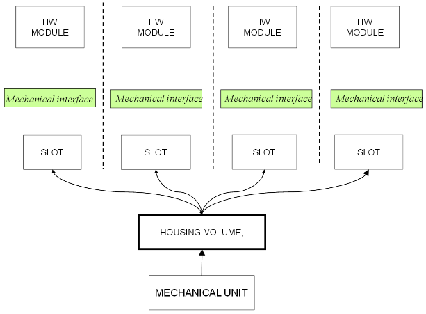
Figure 8: CLASS RH— the relationship between housing elements
2.1.2. Characterisation requirements for ETSO-C153a CLASS RH (F1): Housing
RH.f) The following housing performances or housing characteristics of the rack module shall be provided as part of the characterisation:
1. the size, mass and centre of gravity;
2. the clearance scheme;
3. the top-level drawings and mechanical interfaces;
4. the module mounting scheme;
5. the installation and extraction mechanisms;
6. the temperature control (e.g. airflow, cooling, etc.) performances if the function is implemented;
7. a list of the slots and their associated performances (physical scheme, temperature profile, connector, etc.).
Note: These characterisation requirements are additional to those applicable in Appendix 2.1 — COMMON).
RH.g) The characterisation shall include the description of the mounted hardware module installation and the extraction means and methods.
RH.h) The characterisation shall provide the list of types of slots, their associated attributes, their configurability (if any) and their sizing dimensions (drawings).
This characterisation shall include:
1. the list of authorised or predefined hardware modules (if any);
2. the list of minimum requirements that a hardware module shall comply with to be able to be inserted into the rack;
3. the slot mounting scheme (mechanical profile/drawings) and characteristics (torque, maximum number of insertions, etc.); and
4. the power dissipation and airflow profile.
RH.i) The characterisation, including the usage domain, shall be sufficiently accurate to permit specification and validation of the expected performance of the mounted hardware module.
RH.j) The characterisation shall include the configuration, weight and geometric data that are needed to evaluate the mass and centre of gravity of a populated rack and a partly populated rack.
RH.k) The characterisation shall include the installation instructions of the additional mechanical component that is necessary in order to be compliant with the MPS.
2.2. Requirements for Shielding (F2)
F2 is an optional sub-function of ETSO-C153a CLASS RH.
In this case, the IMA module provides shared resources in terms of the protection of mounted hardware modules. This sub-function merges:
— a level of protection of the mounted hardware modules from the aircraft environment (including, but not only, High Intensity Radiated Fields (HIRF) and Lightning effects); and
— a level of environmental isolation (shielding) between the mounted hardware modules inside the rack.
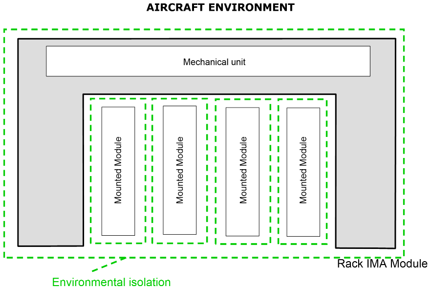
Figure 9: CLASS RH shielding function overview
2.2.1. Functional requirements for ETSO-aC153a CLASS RH (F2): Shielding
RH.l) A level of environmental protection (shielding) for each mounted hardware module shall be ensured by the Rack Housing IMA Module. This protection shall take into account the level and severity retained for the EUROCAE ED-14/RTCA DO-160 qualification of the IMA module (see Appendix 4) (outside the rack), as well as the interactions between the mounted hardware modules themselves (inside the rack).
RH.m) The protection performance of the IMA module (Rack module) shall be quantified and guaranteed for each slot and for each EUROCAE ED-14/RTCA DO-160 Section.
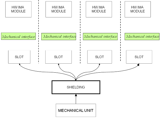
Figure 10: CLASS RH— the relationship between shielding elements
2.2.2. Characterisation requirements for ETSO-C153a CLASS RH (F2): Shielding
RH.o) The level of environmental protection (shielding) of each slot provided in Appendix 2.2, paragraph 2.1.1 shall be characterised, bounded and documented in the installation manual.
RH.p) The characterisation shall include the failure modes and rates of the protection features (such as lightning protections, etc.) to support the IMA system Safety Analysis (as per EUROCAE ED-124) at installation.
RH.q) The characterisation shall include the list of types of slots and the associated characteristics in terms of environmental protection (shielding).
This shall include:
1. the list of authorised or predefined hardware modules (if any);
2. the list of minimum requirements that a hardware module shall comply with in order to be mounted into the rack;
3. a slot Mounting Scheme (mechanical profile/isolation/drawings); and
4. the level of isolation and level of shielding per slot for each EUROCAE ED-14/RTCA DO-160 Section.
RH.r) The characterisation shall include the list of environmental tests that are used to qualify the hardware module (see Environmental Qualification Testing (EQT) in Appendix 4) mounted into the rack.
RH.s) The characterisation shall include all the possible configurations allowed for the configurable slot.
RH.t) If the 0 shielding objective is met thanks to any additional mechanical element(s), its installation shall be specified in the installation manual.
2.3. Requirements for Interconnection (F3)
F3 is an optional sub-function of ETSO-C153a CLASS RH.
In this case, the IMA module provides the capacity to interconnect hardware modules with each other inside the Rack Module. This interconnection allows the exchange of data or the distribution of power.
Note: To ensure the distribution of power to the mounted hardware modules, at least one ETSO-C153a CLASS PS module may be mounted into a slot to deliver electrical energy to the other hardware modules.
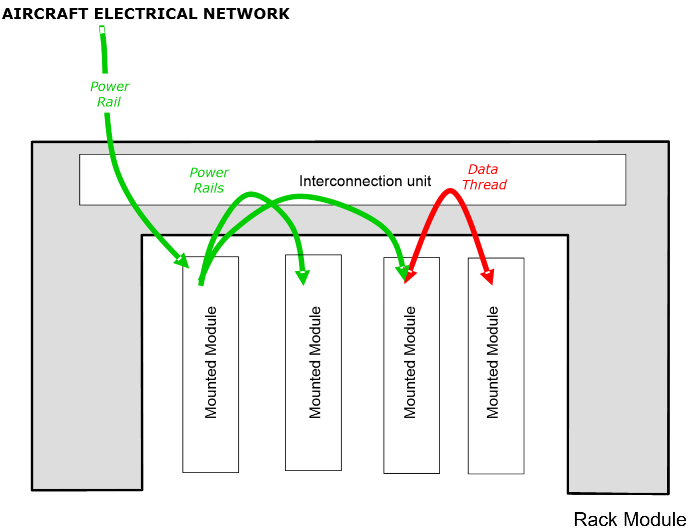
Figure 11: CLASS RH Interconnection function overview
2.3.1. Functional requirements for ETSO-C153a CLASS RH (F3): Interconnection
RH.u) The IMA module shall provide the capacity to interconnect mounted hardware modules thanks to data or power supply buses available through (an) electrical interface(s) supplied by one or several interconnection unit(s). These buses shall be dedicated to:
a. data exchanges; and
b. power distribution.
RH.v) If the IMA module provides more than one bus, the isolation between the buses used by mounted hardware modules shall be ensured by the IMA module. This isolation shall be substantiated by a Partitioning Analysis and by Environmental Qualification Testing.
RH.w) The interface(s) of the IMA module should conform to the characteristics as described by a standard (e.g. ARINC 600 or ARINC 664).
RH.x) The data and power supply buses shall not degrade the transmitted signals below the characterised performance.
RH.y) For ETSO-C153a CLASS RH, the IMA module shall ensure proper isolation of the interconnection function to prevent interference between signals (data, discrete I/O, power supply buses, etc.) that would affect data integrity, latency, and control.
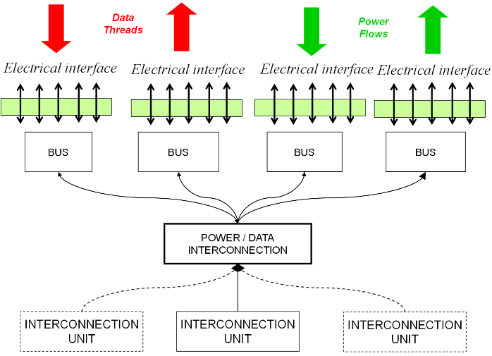
Figure 12: CLASS RH — the relationship between interconnection elements
2.3.2. Characterisation requirements for ETSO-C153a CLASS RH (F3) Interconnection
RH.z) The characterisation shall include attenuation profiles, signal integrity, cross-talk and tolerance rates. These shall be measured and guaranteed.
RH.aa) The performances of each of the types of buses provided in RH.u a) shall be characterised, quantified and guaranteed.
RH.bb) For at least the following failure modes, the failure rate shall be provided:
a. a loss of the interconnection function; and
b. erroneous behaviour of the interconnection function.
RH.cc) The characterisation shall address the safety aspects of sequencing, delay, corruption and impersonation.
RH.dd) The characterisation shall include the list of types of buses, their associated attributes, their configurability, and their sizing and performance.
2.4. Requirements for Temperature control (F4)
F4 is an optional sub-function of ETSO-C153a CLASS RH (F4): Temperature control
In this case, the IMA module provides the capability to control the temperature inside the rack for each mounted module.
This control may be realised by:
— distributing airflow between the aircraft environment (outside the rack) and the mounted hardware modules inside the IMA module (rack);
— enforcing airflow (convection) within the cooling generation unit;
— facilitating conduction between mounted hardware modules and the heat sinkers part of the Rack module.
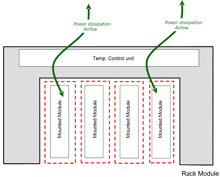
Figure 13: CLASS RH cooling function overview
2.4.1. Functional requirements for ETSO-C153a CLASS RH (F4): Temperature control
RH.ee) The IMA module shall provide regulated temperature control of the mounted hardware module. This control shall be ensured per slot in a determined temperature range.
RH.ff) The IMA module may provide an active means (temperature control unit) to control the temperature between the aircraft environment and the mounted hardware modules.
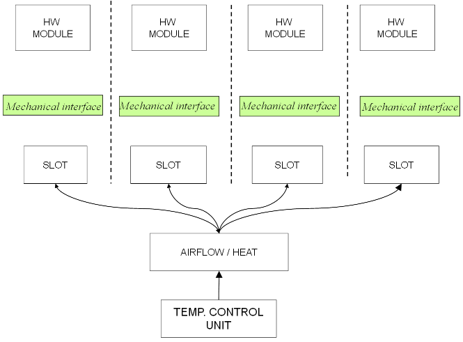
Figure 14: CLASS RH — the relationship between the cooling elements
2.4.2. Characterisation requirements for ETSO-C153a CLASS RH (F4)
RH.gg) The heat exchange performance of each slot provided shall be characterised, quantified and guaranteed in the installation manual.
RH.hh) For at least the following failure modes, the failure rate shall be provided:
a. a loss of the active temperature control function; and
b. erroneous behaviour of the active temperature control function.
The following table gives the verification method for each MPS; nevertheless, an alternative method may be proposed to the certification authority:
Requirement identifier |
Verification method |
Test under normal conditions |
Test under environmental conditions |
Applicable ED-14/DO-160 sections |
RH.a) |
I+T |
Y |
Y(2) |
no ED-14 Section, see (2) |
RH.b) |
T |
Y |
Y |
ED-14 Sections 4, 5, 7 and 8 |
RH.c) |
I+T |
|
Y(2) |
no ED-14 section, see (2) |
RH.d) |
I |
|
|
|
RH.e) |
I/A |
|
|
|
RH.f) |
I |
|
|
|
RH.g) |
I |
|
|
|
RH.h) |
I+A |
|
|
|
RH.i) |
A |
|
|
|
RH.j) |
I+T |
Y |
|
|
RH.k) |
I |
|
|
|
RH.l) |
I |
|
|
|
RH.m) |
T |
Y |
Y |
Appropriate ED-14 sections addressing the shielding characteristics and, as a minimum, Sections 18, 19, 20 and 22 |
RH.n) |
|
|
|
|
RH.o) |
I |
|
|
|
RH.p) |
I |
|
|
|
RH.q) |
I+A |
|
|
|
RH.r) |
I |
|
|
|
RH.s) |
T |
Y |
Y |
Appropriate ED-14 sections addressing the shielding characteristics and, as a minimum, Sections 18, 19, 20 and 22 |
RH.t) |
I |
|
|
|
RH.u) |
T |
Y |
Y(1) |
ED-14 Sections 4, 5, 6, 7, 8, and 16 to 22 |
RH.v) |
A+T |
Y |
Y |
ED-14 Sections 16 to 22 |
RH.w) |
T |
Y |
Y(1) |
ED-14 Sections 4, 5, 7 and 16 to 22 |
RH.x) |
T |
Y |
Y |
ED-14 Sections 4, 5 and 7 |
RH.y) |
A |
|
|
|
RH.z) |
T(A*) |
Y |
|
|
RH.aa) |
T(A*) |
Y(1) |
Y(1) |
ED-14 Sections 4, 5 and 7 |
RH.bb) |
A |
Y |
|
|
RH.cc) |
T(A*) |
Y(1) |
|
|
RH.dd) |
I |
|
|
|
RH.ee) |
T |
Y |
Y |
ED-14 Sections 4 and 5 |
RH.ff) |
I+T |
Y |
Y |
ED-14 Sections 4 and 5 |
RH.gg) |
I+T |
Y |
Y |
ED-14 Sections 4, 5, 6 and 7 |
RH.hh) |
A |
|
|
|
RH.ii) |
|
|
|
|
RH.jj) |
|
|
|
|
Table 2: Verification Acceptance Criteria
(A*) means that verification by the Analysis method is possible for the item that cannot be tested.
Note (1): applicable for a functional subset cf. CO.gg).
Note (2): test to be completed after environmental testing.
[Amdt ETSO/10]
[Amdt ETSO/16]