AMC 29.563 Structural ditching and emergency flotation provisions
ED Decision 2018/007/R
This AMC replaces FAA AC 29.563 and AC 29.563A.
(a) Explanation.
This AMC contains specific structural conditions to be considered to support the ditching requirements of CS 29.801, and the emergency flotation requirements of CS 29.802.
For rotorcraft for which certification with ditching provisions is requested by the applicant, in accordance with CS 29.801(a), the structural conditions apply to the complete rotorcraft.
For rotorcraft for which certification with emergency flotation provisions is requested by the applicant, in accordance with CS 29.802(b): if the passenger capacity of the rotorcraft is less than 10 passengers, the structural conditions apply only to the flotation units and their attachments to the rotorcraft, otherwise they apply to the complete rotorcraft.
At Amendment 5, the requirement for flotation stability on waves was appreciably changed. A requirement for the substantiation of acceptable stability by means of scale model testing in irregular waves was introduced at this amendment. This change made the usage of Sea State (World Meteorological Organization) no longer appropriate. The sea conditions are now defined in terms of significant wave height (Hs) and mean wave period (Tz). These terms are therefore also used in this AMC when defining sea conditions.
(1) The landing conditions specified in 29.563(a) may be considered as follows:
(i) The rotorcraft contacts the most severe sea conditions for which certification with ditching or emergency flotation provisions is requested by the applicant, selected in accordance with Table 1 of AMC to CS 29.801(e) and 29.802(c) and as illustrated in Figure 1 a). These conditions may be simulated considering the rotorcraft contacting a plane of stationary water as illustrated in Figure 1 b), inclined with a range of steepness from zero to the significant steepness given by Ss=2πHs/(gTz2). Values of Ss are given in Table 1 of AMC to 29.801(e) and 29.802(c). The rotorcraft contacts the inclined plane of stationary water with a flight direction contained in a vertical plane. This vertical plane is perpendicular to the inclined plane, as illustrated in Figure 1 b). Likely rotorcraft pitch, roll and yaw attitudes at water entry that would reasonably be expected to occur in service, should also be considered. Autorotation, run-on landing, or one-engine-inoperative flight tests, or a validated simulation should be used to confirm the attitudes selected.
(ii) The forward ground speed should not be less than 15.4 m/s (30 kt), and the vertical speed not less than 1.5 m/s (5 ft/s).
(iii) A rotor lift of not more than two-thirds of the design maximum weight may be assumed to act through the rotorcraft’s centre of gravity during water entry.
(iv) The above conditions may be simulated or tested using a calm horizontal water surface with an equivalent impact angle and speed relative to the water surface as illustrated in Figure 1 c).
(2) For floats that are fixed or intended to be deployed before water contact, CS 29.563(b)(1) defines the applicable load condition for entry into water, with the floats in their intended configuration.
CS 29.563(b)(1) also requires consideration of the following cases:
— The floats and their attachments to the rotorcraft should be designed for the loads resulting from a fully immersed float unless it is shown that full immersion is unlikely. If full immersion is shown to be unlikely, the determination of the highest likely buoyancy load should include consideration of a partially immersed float creating restoring moments to compensate for the upsetting moments caused by the side wind, unsymmetrical rotorcraft loading, water wave action, rotorcraft inertia, and probable structural damage and leakage considered under CS 29.801(e). The maximum roll and pitch angles established during compliance with CS 29.801(e) may be used to determine the extent of immersion of each float. When determining this, damage to the rotorcraft that could be reasonably expected should be accounted for.
— To mitigate the case when the crew is unable to, or omits to, deploy a normally stowed emergency flotation system before entering the water, it should be substantiated that the floats will survive and function properly. The floats in their un-deployed condition, their attachments to the rotorcraft and the local structure should be designed to withstand the water entry loads without damage that would prevent the floats inflating as intended. Risks such as the splintering of surrounding components in a way that might damage the un-deployed or deploying floats should be considered. There is, however, no requirement to assess the expected loading on other parts of the rotorcraft when entering the water, with unintended un-deployed floats.
— The floats and their attachments to the rotorcraft should be substantiated as capable of withstanding the loads generated in flight. The airspeed chosen for assessment of the loads should be the appropriate operating limitation multiplied by 1.11. For fixed floats, the operating limitation should be the rotorcraft VNE. For deployable floats, if an operating limitation for the deployment of floats and/or flight with floats deployed is given, the highest such limitation should be used, otherwise the rotorcraft VNE should be used.
(3) For floats intended to be deployed after water contact, CS 29.563(b)(2) requires the floats and their attachments to the rotorcraft to be designed to withstand the loads generated when entering the water with the floats in their intended condition.
Simultaneous vertical and drag loading on the floats and their attachments should be considered to account for the rotorcraft moving forward through the water during float deployment.
The vertical loads should be those resulting from fully immersed floats unless it is shown that full immersion is unlikely. If full immersion is shown to be unlikely, the determination of the highest likely buoyancy load should include consideration of a partially immersed float creating restoring moments to compensate for the upsetting moments caused by side wind, unsymmetrical rotorcraft loading, water wave action, rotorcraft inertia, and probable structural damage and leakage considered under CS 29.801(e). The maximum roll and pitch angles established during compliance with CS 29.801(e) may be used, if significant, to determine the extent of immersion of each float. When determining this, damage to the rotorcraft that could be reasonably expected should be accounted for.
The drag loads should be those resulting from movement of the rotorcraft through the water at 10.3 m/s (20 knots).
(b) Procedures
(1) The floats and the float attachment structure should be substantiated for rational limit and ultimate loads.
(2) The most severe sea conditions for which certification is requested by the applicant are to be considered. The sea conditions should be selected in accordance with the AMC to 29.801(e) and 29.802(c).
(3) Landing load factors and the water load distribution may be determined by water drop tests or validated analysis.

a) Water entry into wave

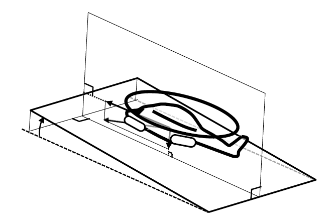
b) Water entry into inclined plane of stationary water, steepness range - zero to significant steepness (Ss)
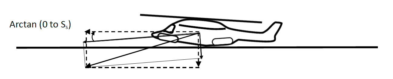
c) Water entry into a stationary horizontal water surface using an equivalent water entry angle and velocity relative to the water surface
(Dashed arrows show required horizontal and vertical speeds)
Figure 1 – Illustration of water entry test or simulation conditions which may be considered for structural provisions assessment.
[Amdt No: 29/5]